HAL Id: tel-01924552
https://pastel.archives-ouvertes.fr/tel-01924552
Submitted on 16 Nov 2018
HAL is a multi-disciplinary open access
archive for the deposit and dissemination of sci-entific research documents, whether they are pub-lished or not. The documents may come from teaching and research institutions in France or abroad, or from public or private research centers.
L’archive ouverte pluridisciplinaire HAL, est destinée au dépôt et à la diffusion de documents scientifiques de niveau recherche, publiés ou non, émanant des établissements d’enseignement et de recherche français ou étrangers, des laboratoires publics ou privés.
Study and design of a thermodynamic system generating
mechanical work from a hot source at 120°C
Samer Maalouf
To cite this version:
Samer Maalouf. Study and design of a thermodynamic system generating mechanical work from a hot source at 120°C. Other. Ecole Nationale Supérieure des Mines de Paris, 2013. English. �NNT : 2013ENMP0074�. �tel-01924552�
MINES ParisTech
Centre d’Efficacité Energétique des Systèmes (CES)
5, rue Léon Blum, 91120 Palaiseau
T
T
H
H
E
E
S
S
E
E
École doctorale n° 432 : Sciences des Métiers de l’Ingénieur
présentée et soutenue publiquement par
Samer MAALOUF
le 27 septembre 2013
Etude et conception d’un système thermodynamique producteur
du travail mécanique à partir d’une source chaude à 120°C
Study and design of a thermodynamic system generating
mechanical work from a hot source at 120°C
Thèse confidentielle
(date de fin le 27/09/2018)
Doctorat ParisTech
T H È S E
pour obtenir le grade de docteur délivré par
l’École nationale supérieure des mines de Paris
Spécialité “ Energétique ”
Directeur de thèse : Denis CLODIC
Co-encadrement de la thèse : Elias BOULAWZ KSAYER Jury
M. Jocelyn BONJOUR, Professeur, INSA de Lyon Rapporteur
M. Michel FEIDT, Professeur des Universités, LEMTA Rapporteur
M. Predrag HRNJAK, Professeur, University of Illinois Rapporteur
M. Denis CLODIC, Directeur de recherche émerite, CES, MINES ParisTech Examinateur
«
The greatest challenge to any thinker is stating the problem in a way that will allow a
solution
»«
Le plus grand défipourtout penseurest de poser leproblème d'une manièrequi permettra une solution»Acknowledgement
It would not have been possible to write this doctoral thesis without the help and support of the kind people around me, to only some of whom it is possible to give particular mention here.
The first person I would like to thank is my principal supervisor Denis Clodic, President and Director of “EReIE Company”. His wisdom, knowledge, and commitment to the highest standards inspired and motivated me.
I would like to express my deepest gratitude to my supervisor Elias BouLawz Ksayer for his excellent guidance, caring, patience, and helping me to develop my background in research, not to mention his advice and unsurpassed knowledge. His support has been invaluable on both an academic and a personal level, for which I am extremely grateful.
I would like to thank Maroun Nemer, Director of “CES”, who provided me valuable comments, continuous advice and offered me an excellent environment for research.
Special thanks to Jocelyn Bonjour, Michel Feidt and Predrag Hrnjak, for accepting to be members of the Examination Board and evaluating my work.
I would like to express my sincere appreciation and gratitude to Anne-Marie Bonnet for her professional and linguistic involvement.
I gratefully acknowledge Olivier Calmels and Ludovic De Oliveira, whom partly contributed to my work. Their involvement, scientific intuition, and technical competences were of great assistance.
I would like to thank also the working team of the Center for Energy and Systems Efficiencies
“CES”, who created a suitable environment for me to work.
Finally, I wish to express my gratitude to my Parents, whom always supporting me and encouraging me with their best wishes.
Nomenclature i
Nomenclature
Symbol
A, S section area m-2
a specific surface area m2.m-3
b corrugation base length m
B surface ratio -
BV burning velocity cm.s-1
C coil characteristic -
c heat transfer exponent -
cp specific heat capacity J.kg
-1
.K-1
D, d diameter m
D diffusion coefficient m2.s-1
DT temperature difference / pinch K
DP pressure drop Pa
Dh enthalpy difference kJ.kg-1
DTLM log mean temperature difference K
E, Ex exergy kJ.kg-1
e thickness m
f fanning friction factor -
F load factor m.s-1.(kg.m-3)0.5
G mass velocity kg.m-2.s-1
h mass enthalpy kJ.kg-1
h heat transfer coefficient W.m-2.K-1
h corrugation height m
hL liquid hold-up %
hfg latent heat of vaporization kJ.kg
-1 H height m I irreversibility kJ.kg-1 I flammability -j colburn j-factor - J superficial velocity m.s-1
k mass transfer coefficient m.s-1
k thermal conductivity W.(m.K)-1
L length m
LNF number of fins per linear meter m-1
Lv latent heat of vaporization kJ.kg-1
M molar mass g.mol-1
m mass flow rate kg.s-1
m fin parameter -
MIE minimum ignition energy mJ
n moles number mol
P pressure Pa q heat flux W.m-2 Q heat capacity kJ.kg-1 R thermal resistance K.W-1 r radius mm s mass entropy kJ.(kg.K)-1
s corrugation side length m
SC sub-cooling K
SH superheat K
T temperature °C
V volume m3
V, u velocity m.s-1
Nomenclature ii
w absolute humidity kg.kg-1dg
W power kJ.kg-1
x vapor quality -
y dry mass fraction / molar fraction adim
Greek letters
efficiency %
μ chemical potential kJ.kg-1
∆ relative variation %
Ʈ turbine expansion ratio -
α slope of the saturation vapor line -
α corrugation angle °
ρ density kg.m-3
ξ friction factor -
ζ overall coefficient losses -
ψ fraction of gas flow channels ending at column walls -
σ, γ surface tension N.m-1
φ heat flux W.m-2
ξ mass fraction of lithium-bromide -
δ thickness mm
θ angle °
λ thermal conductivity W.(m.K)-1
ε void fraction -
Ω loading point constant -
Subscripts
a air / dry flue gases
c condensate / convective / circuit cond condenser cr critical point D division d dry DC direction change dp dew point dg dry gases
evap evaporator/ evaporation
e effective f fin fr frontal G, g gas H high / horizontal i inside in inlet is isentropic
L low / liquid / longitudinal / lithium bromide
m mean / metal
max maximal
nb normal boiling
o reference conditions / outside / overall out outlet
p pitch / pump / packing
pb packing bed
Nomenclature iii
pnb pool normal boiling r refrigerant
s spacing / superficial / surface / solid / saturated sw saturated water
T transversal
t turbine/ total / tube tp two-phase / triple point v volume / vertical / vapor w wet / wall/ water
wb wet bulb wf working fluid wv water vapor Abbreviations CT Cooling tower CU Condensing unit
GWP Global Warming Potential (kgCO2eq.kg -1
wf)
HEX Heat exchanger
HFC Hydro - Fluoro – Carbon NBP Normal Boiling Point NBP Number of Transfer Unit ODP Ozone Depletion Potential EU Evaporating Unit Non-dimensional numbers . h D Nu k Nusselt number . Pr cp k Prandtl number . . Re V D Reynolds number 2 2 . . l l G Fr g D Froude number Re n D r R Dean number . Sc D Schmidt number . k L Sh D Sherwood number
Contents
CONTENTS
GENERAL INTRODUCTION ... 1
CHAPTER 1:
STUDY AND DESIGN OF THERMODYNAMIC CYCLES FOR
LOW TEMPERATURE HEAT SOURCES ... 3
1.1 LOW-TEMPERATURE WASTE HEAT RECOVERY:POTENTIAL AND CHALLENGE ... 3
1.1.1 Prioritization of industrial gas-waste heat sources ... 3
1.1.2 Low-temperature waste heat: large and unexploited heat sources ... 4
1.1.3 Challenges to recovering low-temperature waste heat ... 7
1.1.3.1 Non-conventional heat sources ... 7
1.1.3.2 Heat extraction ... 7
1.1.3.3 Conversion ... 9
1.2 ENERGY AND EXERGY RECOVERY FROM LOW-TEMPERATURE HEAT SOURCES ... 9
1.2.1 Heat load and exergy availabilities ... 10
1.2.2 Ideal overall and exergy efficiencies ... 13
1.3 POWER GENERATION CYCLES ... 14
1.3.1 Organic Rankine Cycle ... 15
1.3.2 Kalina Cycle ... 15
1.4 LOW-TEMPERATURE HEAT EXCHANGE ... 16
1.4.1 Indirect Contact Water-Vapor Condensation Recovery ... 16
1.4.2 Direct Contact Water-Vapor Condensation Recovery ... 17
1.4.3 Transport Membrane Condenser ... 17
1.5 SIMPLE ORC WITH INDIRECT-CONTACT HEAT RECOVERY ... 18
1.5.1 Simple ORC with direct evaporator ... 18
1.5.1.1 Parameters of the simple ORC ... 18
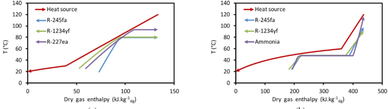
1.5.1.2 Results and interpretations ... 21
1.5.2 Simple ORC with indirect evaporator ... 26
1.6 ORC WITH DIRECT-CONTACT HEAT RECOVERY ... 28
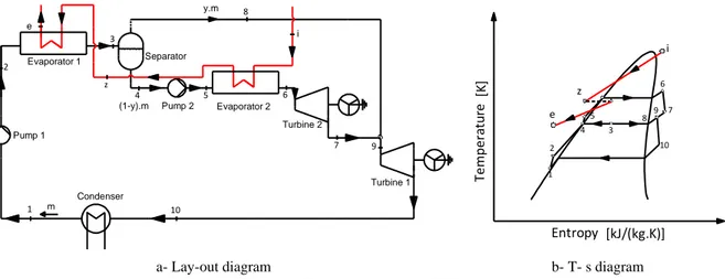
1.7 TWO-STAGE ORC ... 33
1.7.1 Typical two-stage ORC ... 33
1.7.2 Improved two-stage ORC ... 36
1.7.3 Two-stage ORC using direct-contact condensation at the low-pressure stage ... 37
1.8 NET POWER COMPARISON BETWEEN THE HEAT RECOVERY MODES ... 38
1.9 EFFECT OF AUXILIARY CONSUMPTIONS ON ORC PERFORMANCES ... 39
1.9.1 Effect of auxiliary consumptions on condensation pressure ... 40
1.9.2 Effect of auxiliary consumptions on evaporator superheat ... 41
1.9.3 Effect of auxiliary consumptions on evaporation temperature ... 41
1.9.4 Effect of auxiliary consumptions on working fluid selection ... 42
1.9.5 Pure working fluid ... 43
1.9.6 Binary blends as working fluid ... 47
1.9.6.1 Binary blends for simple ORC with indirect-contact condensation ... 47
1.9.6.2 Binary blends for simple ORC with direct-contact condensation ... 50
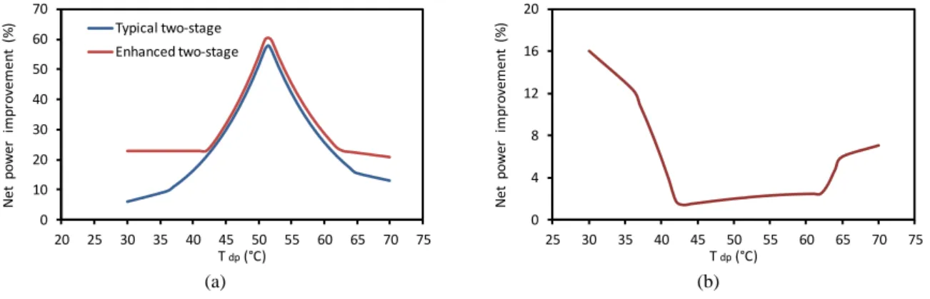
1.9.6.3 Enhanced two-stage ORC with binary blends ... 53
1.9.7 Effects of auxiliary consumptions on heat recovery modes ... 54
1.10 TRANS-CRITICAL ORGANIC RANKINE CYCLE ... 55
1.10.1 Trans-critical ORC with R-134a, R-1234yf, R-1234ze, and R-32 as working fluids ... 56
1.10.2 Trans-critical ORC with carbon dioxide as working fluid ... 56
1.11 CONCLUSIONS ... 57
REFERENCES ... 60
CHAPTER 2:
INDIRECT CONTACT-CONDENSATION HEAT RECOVERY ... 63
Contents
2.2 CHEMISTRY OF THE CONDENSING FLUE GASES ... 63
2.2.1 Acid dew point calculations ... 64
2.2.2 Heat-exchanger corrosion zones ... 65
2.2.3 Potential solutions for acid corrosion ... 67
2.3 GENERAL DESIGN METHOD FOR FIN-AND-TUBE HEX AT LOW TEMPERATURE ... 67
2.3.1 Design criteria ... 68
2.3.2 Heat and mass transfer model ... 71
2.3.2.1 Heat-transfer model ... 71
2.3.2.2 Mass transfer model ... 75
2.3.3 Optimization procedure ... 77
2.3.3.1 Operating parameters ... 77
2.3.3.2 Tube length ... 79
2.3.3.3 Fin types and fin pitches ... 80
2.3.3.4 Tube diameters and tube pitches ... 81
2.3.3.5 Fin-and-tube heat exchanger circuitry ... 82
2.3.4 Effect of evaporation pressure on fin-and-tube heat-exchanger parameters ... 82
2.3.5 Effect of material selection on fin-and-tube heat-exchanger parameters ... 83
2.4 CONDENSATION MODES ... 84
2.5 EXPERIMENTAL METHODS ... 85
2.5.1 Description of the heat-exchanger specimens ... 85
2.5.2 Experimental apparatus and procedure ... 87
2.6 DATA REDUCTION AND INTERPRETATION ... 89
2.7 TESTS RESULTS AND DISCUSSION ... 90
2.7.1 Dry-condition test data ... 91
2.7.2 Partially wet-condition test data ... 96
2.8 CONCLUSIONS ... 99
REFERENCES ... 101
CHAPTER 3:
DIRECT CONTACT-CONDENSATION HEAT RECOVERY ... 103
3.1 INTRODUCTION ... 103
3.2 DESIGN OF A CONDENSING UNIT ... 103
3.2.1 Description of a Condensing unit ... 103
3.2.2 Packing types and corrugation geometry ... 104
3.2.3 Hydraulics of the condensing unit ... 107
3.2.4 Heat and mass transfer model inside the packing ... 109
3.2.5 Hydraulics and mass transfer predicting model for structured packing ... 113
3.2.5.1 Liquid hold-up ... 114
3.2.5.2 Pressure drop ... 115
3.2.5.3 Effective surface area ... 118
3.2.5.4 Mass transfer coefficients ... 118
3.2.5.5 Heat-transfer coefficients ... 119
3.3 MODEL SIMULATION AND RESULTS ... 120
3.4 EXPERIMENTAL METHODS ... 123
3.4.1 Description of the lab-scale condensing unit ... 123
3.4.2 Experimental apparatus and procedure ... 125
3.4.3 Data reduction and interpretation ... 128
3.5 TESTS RESULTS AND DISCUSSION ... 128
3.5.1 Experimental pressure drop at the airside ... 129
3.5.2 Comparison of the overall heat-transfer coefficient ... 130
3.5.3 Comparison between the predicted and correlated heat-exchange capacity ... 131
3.6 CONCLUSIONS ... 132
Contents
CHAPTER 4:
INNOVATIVE THERMODYNAMIC CYCLES FOR
LOW-TEMPERATURE WET HEAT SOURCES ... 136
4.1 INTRODUCTION ... 136
4.2 REVIEW OF THE EXISTING HEAT RECOVERY TECHNOLOGIES ... 137
4.3 DESICCANT: OPERATION AND SELECTION ... 139
4.3.1 Desiccant operation ... 139
4.3.2 Liquid sorption ... 139
4.3.3 Desiccant selection ... 140
4.4 PROPERTIES OF AQUEOUS LITHIUM-BROMIDE SOLUTION ... 141
4.4.1 Composition ... 141
4.4.2 Vapor pressure ... 141
4.4.3 Heat capacity and enthalpy of water – lithium bromide solutions ... 142
4.4.4 Equilibrium chart (“Dühring” Plot)... 144
4.5 DIRECT-CONTACT CONDENSATION USING AQUEOUS LITHIUM-BROMIDE SOLUTION ... 144
4.6 REGENERATION PROCESS USING SOLAR ENERGY ... 149
4.7 CONVENTIONAL REGENERATION CYCLE (CRC) USING AN EVAPORATING UNIT ... 154
4.8 IMPROVED REGENERATION CYCLE (IRC) ... 156
4.8.1 Operating point ... 157
4.8.2 Effect of water dew point temperature ... 159
4.8.3 Effect of condensation temperature ... 160
4.9 MODEL VALIDATION USING “ASPEN” SOFTWARE ... 161
4.10 CONCLUSIONS ... 162
REFERENCES ... 164
GENERAL CONCLUSIONS ... 165
ANNEX A: EVALUATION OF THE CHEMICAL EXERGY ... 169
ANNEX B: COOLING TOWER PARAMETERS ... 170
ANNEX C: OPTIMIZATION PROCEDURES ... 171
ANNEX D: HEAT-TRANSFER AND PRESSURE DROP CORRELATIONS USED IN
FIN-AND-TUBE HEAT EXCHANGER ... 176
ANNEX E: TEST-BENCH DESCRIPTION ... 180
ACKNOWLEDGEMENTS: APPLICATION OF THE RESULTS AND FRAMEWORK
TO THE CEMENT PRODUCTION INDUSTRY ... 190
General introduction 1
General introduction
The valorization of waste heat within processes in industry undoubtedly plays a crucial role in improving overall energy efficiency of those processes. When there is no potential use of process waste heat, or when high-temperature waste heat has already been used inside the process itself or possibly with the surrounding community, the conversion of the remaining heat (< 120 to 150°C) in electricity should be considered. Investigation of current waste-heat recovery practices shows that waste heat is generally recovered from clean, high-temperature waste heat sources in large capacity systems. Most unrecovered waste heat (more than 50%) is at low temperatures (< 120-150°C). Due to lack of efficient recovery methods, low-grade waste heat has generally been discarded in industry. While low-temperature waste heat has less thermal and economic value than high-temperature heat, it is ubiquitous and available in large quantities. The field of low-temperature waste heat is addressed through novel science and ambitious technological solutions.
Low-temperature heat valorization faces technical barriers that impede their wider application. The maximum thermodynamic efficiency represented by the Carnot factor is only around 25%. Heat extraction challenges arise from the fact that large heat-transfer areas for heat exchangers are required due to the low-temperature level. In addition, industrial flue gases may contain high-moisture content and there would be significant benefits to cooling flue gases to temperatures below the water-vapor dew point. However, the presence of pollutant substances (SOx, NOx…) is of particular concern
because of potential corrosion of heat exchangers.
The thesis focuses on particularly energy-hungry industrial sectors characterized by presently unsolved challenges in terms of environmentally hostile low-temperature heat sources. It will open very important technological perspectives of increased energy efficiency through low-temperature waste heat valorization by way of electricity production. The results from this thesis are identified in two broad areas: 1) extending the range of existing technologies to low-temperature level in order to enhance their feasibility and recovery efficiency, and 2) exploring new methods for waste heat recovery.
Chapter 1 details the heat recovery options from low-temperature waste heat for generating electrical power using the well-proven Organic Rankine Cycle (ORC). Current recovery technologies include indirect and direct-contact water-vapor condensation recovery depending on which the heat is transferred between the hot stream (flue gases) and the cold stream (working fluid) using or not an intervening wall respectively. The effects of water-vapor condensation on cycle performance using the two condensing heat recovery processes (direct and indirect heat exchange) are pointed out. Thermodynamic optimization is conducted in order to maximize the net power produced. The impacts of auxiliary consumptions on the ORC behavior are studied. The benefits of using a blend as working fluid instead of pure working fluid when computing auxiliary consumptions are highlighted.
Chapter 2 presents the heat recovery from low-temperature heat sources using an indirect-contact heat-recovery process (fin-and-tube heat exchanger). A theoretical prediction for acid dew-point calculations is presented and the typical corrosion zones in the heat exchanger are identified. A general method to design the fin-and-tube heat exchanger adapted to low-temperature level has been elaborated. Advanced coating materials that can minimize chemical attack by cooling exhaust gases below the acid and water dew points are proposed and laboratory tested. The impacts of surface wet-abilities on thermal hydraulic performances of the fin-and-tube heat exchanger are underlined.
General introduction 2
Chapter 3 deals with the process of direct-contact heat transfer between flue gases and water flowing counter-currently in a condensing unit filled with packing materials. General design method for the condensing unit based on hydraulics parameters (pressure drop and liquid hold-up) and on heat and mass transfer between flue gases and water inside the packing is elaborated. Experimental studies are performed in order to validate the developed model and to examine performances of various packing types with distinct surface geometry and wet-ability on the condensing unit behavior.
In chapter 4, innovative opportunities are proposed by developing new heat-recovery technologies for replacing existing ones enabling heat recovery from heat sources with high-moisture contents and therefore increasing effective options for heat recovery. Novel thermodynamic cycles based on the liquid desiccant technology are presented. The water sorption characteristics of desiccant materials are discussed and the implications of those characteristics in low-temperature heat recovery systems are explained.
Chapter 1: Study and design of thermodynamic cycles for low-temperature heat sources 3
Chapter 1: Study and design of thermodynamic cycles for low temperature
heat sources
1.1 Low-temperature waste heat recovery: Potential and Challenge
In December 2008, under the “20-20-20” designation, the European Parliament adopted the EU climate change package (SET-Plan 1) with the aim of reaching three main energy-climate targets by 2020: (a) 20% greenhouse gases (GHG) emissions reduction, (b) 20% energy efficiency increase, and (c) 20% renewable energies share in the EU energy mix [DUP 09]. In the EU 27, the industry sector represents 28% of the final energy consumption, 21% of the GHG emissions and it must therefore be considered in the 20-20-20 context [FP7 07]. Efforts to improve industrial energy efficiency focus on reducing the energy consumed by the equipment used in manufacturing (e.g. boilers, furnaces, dryers, reactors…). Using Best Available Technologies (BATs), energy savings of 20% are reachable in the European industrial sector. A valuable approach to improve overall energy efficiency is to recover and reuse the waste heat that is intrinsic to all industrial manufacturing. Waste heat recovery implies capturing and reusing the waste heat in industrial processes for heating or for generating mechanical or electrical power. The exact quantity of industrial waste heat is poorly quantified, but various studies have estimated that as much as 20 to 50% of industrial energy consumption is ultimately discharged as waste heat [BCS 08]. While some waste heat losses from industrial processes are inevitable, facilities can reduce these losses by improving equipment efficiency or installing waste heat recovery technologies.
1.1.1 Prioritization of industrial gas-waste heat sources
Typical waste-gas heat sources include combustion exhausts such as glass melting furnace, cement kiln, incinerator, aluminum furnace, and boiler. Waste heat losses arise both from equipment inefficiencies and from thermodynamic limitations on equipment and processes [WEN 13]. For example, consider furnaces frequently used in aluminum melting operations: exhaust gases leaving the furnace can have temperatures as high as 1200-1300°C. Consequently, these gases have high heat content, carrying away as much as 60% of furnace energy inputs. Efforts can be made to design more energy efficient furnaces with better heat transfer and lower exhaust temperatures; however, the laws of thermodynamics place a lower limit on the temperature of exhaust gases. Since heat exchange involves energy transfer from a high temperature source to a lower temperature sink, the combustion gas temperature must always exceed the molten aluminum temperature in order to facilitate aluminum melting. The gas temperature in the furnace will never decrease below the temperature of the molten aluminum. Therefore, the minimum possible temperature of combustion gases immediately exiting an aluminum furnace corresponds to the aluminum pouring point temperature from 650 to 750°C. In this scenario, at least 40% of the energy input to the furnace is still lost as waste heat.
To better calculate a realistic potential of waste heat, several guidelines suggest a prioritization of waste heat recovery [WEN 13]. First, avoiding waste heat should be prioritized over recovering waste heat. Before implementing waste heat recovering actions, one should first think of possibilities to avoid the creation of waste heat through more efficient equipment or control systems. If waste heat is unavoidable, one should prioritize the reuse of waste heat to substitute heat demand for secondary processes within the production system on site (heat exchanger, heat pumps, heat storage…). For example, the use of the combustion exhaust gases to preheat combustion air or feed-water in industrial boilers. By preheating the feed-water before it enters the boiler, the amount of energy required to heat the water to its final temperature is reduced. Alternately, the heat can be transferred to another process;
Chapter 1: Study and design of thermodynamic cycles for low-temperature heat sources 4
for example, a heat exchanger could be used to transfer heat from combustion exhaust gases to hot air needed for a drying oven. In this manner, the recovered heat can replace fossil energy that would have otherwise been used in the oven.
Once on-site heat reutilization is exploited, the possibility to reuse heat for neighboring sites and district heating grids should be used. Only if heat reutilization is fully exploited on- and off-site, one can use the remaining waste heat for electricity generation. These prioritization rules are incorporated in an energy flow diagram, which illustrates the method for evaluating waste heat recovery potential (Fig. 1.1). In Stage 1, the total waste heat potential is quantified and characterized in a chosen sector. During Stage 2, the potential of avoidable waste heat will be estimated. Stage 3 is evaluating the on-site reusable waste heat potential. Finally, in Stage 4, the off-on-site reusable waste heat potential is assessed.
Fig. 1.1: Prioritization and recovery options for industrial gas waste heat sources [WEN 13]
Such methods for recovering waste heat can help facilities significantly reduce their fossil fuel consumption, as well as reduce associated operating costs and pollutant emissions. Another advantage of waste heat recovery is that it can reduce capacity requirements for facilities thermal conversion devices, leading to reductions in capital costs. In addition to the economic benefits of waste heat recovery for the facility, waste heat recovery is a green-house-gas-free source of energy. Reducing the fossil fuel demand will result in accompanying reductions in greenhouse-gas emissions.
1.1.2 Low-temperature waste heat: large and unexploited heat sources
Investigation of current waste-heat recovery practices shows that waste heat is generally recovered from clean, high-temperature waste-heat sources in large capacity systems. Most unrecovered waste heat, more than 50%, is at low temperatures (< 150°C) [BCS 08]. Due to lack of efficient recovery methods, low-grade waste heat has generally been discarded in industry. While low-temperature waste heat has less thermal and economic value than high-temperature heat, it is ubiquitous and available in large quantities. Literature reveals that the total work potential of low-temperature waste heat is sufficiently large that it should not be neglected in pursuing researches and development opportunities for waste heat recovery [FP7 07].
As shown in Fig. 1.2, when there is no potential use of process waste heat or when high-temperature waste heat has already been used inside the process itself or possibly with the surrounding community, the conversion of the remaining heat (low-temperature heat <120°C) in electricity should be considered. The field of low-temperature waste heat is addressed through novel science and ambitious technological solutions.
Chapter 1: Study and design of thermodynamic cycles for low-temperature heat sources 5
Fig. 1.2: Process industry waste heat recovery principle [FP7 07]
In order to illustrate the potential of low-temperature heat sources (100-150°C), Fig. 1.3 shows the repartition of waste heat by temperature in the French industry.
Fig. 1.3: Repartition of waste heat in the French industry by temperature [CER 99]
Fig. 1.3 shows that the waste heat sources within the interval 100 to 150°C represents around 16% of the total waste heat, resulting in a 17.5 TWh/yr of energy recovered. In quantitative terms, assuming an overall efficiency of the order of 4%, 700 GWh/yr of electrical energy could be potentially produced through waste heat recovery in the temperature range (100 to 150°C) in the French industry.
Fig. 1.4: Repartition of waste heat (100 to150°C) in the French industry by industrial sectors [CER 99]
Fig. 1.4 shows the repartition of waste heat (100 to 150°C) in the French industry by industrial sectors. Waste heat is mainly released in the food, chemical, cement, and fertilizers industries. The drying exhaust represents the major part of the waste heat in the food, chemical, fertilizers, and milk industries, while the kiln exhaust accounts for the major portion in the cement industry.
<60°C 33% 60-100°C 21% 100-149°C 16% 150-249°C 19% 250-349°C 4% 350-499°C 5% >500°C 2%
Waste heat in the French industry by temperature (109 TWh) 0 0,51 1,5 2 2,5 3 3,5 4 4,5 (T W h )
Waste heat between 100-150°C
Boilers exhaust Kilns, reactor, ovens exhaust Drying exhaust
Chapter 1: Study and design of thermodynamic cycles for low-temperature heat sources 6
The cement industry represents one of the most energy-intensive industrial sectors, since it accounts for 8% of the energy use in industry and 25% of the energy and process CO2 emissions worldwide. It
represents one of the main applications about low-temperature waste-heat recovery.
Fig. 1.5: Dry cement process flow diagram [CEM 99]
In order to better understand and identify the waste heat released in the cement industry, Fig. 1.5 depicts a process diagram for a dry cement production process [CEM 99]. The cement production process consists of five main steps: mining and extraction of limestone and clay, mixing of the raw materials, grinding and drying of the raw meal, clinker production in a pre-heater and kiln system, mixing with additional materials and grinding of the resulting cement powder. The raw materials are crushed and grinded in the raw mill. Then it goes through the cyclone pre-heater to the rotary kiln where pyro-chemical reactions take place at around 2000°C. Directly afterwards, the hot clinker is quickly cooled down to 100 to 200°C and stored for further processing. After the clinker and additives are grinded in the cement mill, the resulting powder is the finished cement [BOR 13].
Based on this process diagram, four main waste heat sources can be identified. Those are (1): clinker cooler gases, (2): kiln combustion gases, (3): bypass gases, and (4): cement mill gases. Flue gases are released into the atmosphere at the raw mill exit and after cleaning, at 120°C or below. Low-temperature gases are also released at the cement mill exit (< 120°C). The bypass gases appear in low quantities (2% of energy consumption) and do not exist in every cement factory. Clinker cooler gases exit at relatively high temperature (~ 400°C).
Table 1.1 shows the potential of low-temperature waste heat in the cement sector (France, Germany, and Poland). The total available low-temperature waste heat is around “3.84 TWh/yr” leading to a total available exergy around “0.56 TWh/yr”.
Table 1.1: Potential of low-temperature waste heat in the cement sector (France, Germany & Poland) [BOR 13]
Country Waste heat source Temperature (°C) Waste heat (TWh/yr) Exergy (TWh/yr)
France Rawmill gases 100°C - 120°C 1.0 0.1
Cement mill gases 100°C - 120°C 0.2 0.05
Germany Raw mill gases 100°C - 120°C 1.4 0.2
Cement mill gases 100°C - 120°C 0.29 0.07
Poland Raw mill gases 100°C - 120°C 0.8 0.1
Cement mill gases 100°C - 120°C 0.15 0.04
Chapter 1: Study and design of thermodynamic cycles for low-temperature heat sources 7
Another example on low-temperature waste heat application is the iron and steel industry. Low-temperature gases are released into the atmosphere at the blast furnaces exit and after, at 150°C or below. Table 1.2 shows the potential of low-temperature waste heat in the iron and steel industry at the blast furnace exit (France and Germany). The total available low-temperature waste heat is around “4.41 TWh/yr” resulting to a total available exergy around “0.90” TWh/yr”.
Table 1.2: Potential of low-temperature waste heat in the iron and steel industry (France and Germany) [BOR 13]
Country Waste heat source Temperature (°C) Waste heat (TWh/yr) Exergy (TWh/yr)
France
Blast furnace gases < 150°C 1.15 0.2
Germany 3.26 0.7
Total - - 4.41 0.90
In quantitative terms, assuming an overall efficiency in the range of 4%, 153 GWh and 176 GWh of electrical energy can be potentially produced, through waste heat recovery on gas exit of, respectively, raw/cement mills and iron-steel industries (France, Germany, and Poland).
1.1.3 Challenges to recovering low-temperature waste heat
From thermodynamic and thermal points of views, generating power from waste heat recovery below 120°C is a challenging task. Three main scientific and technical challenges identified are as follows.
1.1.3.1 Non-conventional heat sources
State-of-the-art heat recovery technologies require a minimum temperature of 150°C to work efficiently. In thermally optimized industrial processes, only a limited amount of high-temperature heat is available. The number of potential heat sources in low-temperature streams (< 120°C) is limited, although their energy content is significant. Presently, low-temperature waste heat sources are mainly valorized to provide heat to other applications and only rarely, to produce electricity, often considered as less attractive. However, generating electricity represents a rational alternative, since it circumvents drawbacks linked to heat demand seasonality and location.
1.1.3.2 Heat extraction
The heat extraction from low-temperature waste streams is often closely connected with material corrosion problems. Depending on the fuel used, combustion-related flue gases contain varying concentrations of carbon dioxide, water vapor, nitric oxides, and sulfuric oxides. In addition, most of the low-temperature gas streams have high moisture contents associated to many processes such as flashing, washing, cleaning, and drying. The water dew point of these heat sources could range from 30°C (~ 4% moisture, dry heat sources) up to 70°C (~ 30% moisture, wet heat sources) [FP7 07]. Example on drying process is the raw mill exit gas in cement industry. During the raw mill preparation, the raw mill gas will be charged with moisture when drying of the raw material in the mill. The charged moisture varies during the year, depending on the moisture content of the material that is driven by seasons and weather conditions.
Cooling the flue gas below the water vapor dew point could significantly increase heat recovery by allowing the latent heat of vaporization to be recovered. However, in this case, the water vapor in the gas will condense and react with sulfuric and nitric oxides, resulting in a corrosive substance deposition on the heat-exchanger surface that will reduce heat-transfer rates, lifetimes, and lead to increased pressure drops and reduced efficiency. In this case, heat exchangers designed from low-cost materials will quickly fail due to chemical attack. Material constraints and costs associated with high
Chapter 1: Study and design of thermodynamic cycles for low-temperature heat sources 8
chemical activity streams require more advanced recovery equipment materials to withstand corrosive environments.
Another challenge for heat exchangers when working with low-temperature fluids is the large heat transfer area required. Fig. 1.6 shows the influence of temperature difference on required heat-exchanger area. It shows the surface area required for recovering “1 MWth” from a gaseous exhaust
stream. “ΔT” denotes the difference in temperatures between heat source and heat sink. The expression for heat transfer can be generalized by the following equation:
Q = U.A.∆T Eq.1.1
Where: “Q” is the heat-transfer rate; “U” is the heat-transfer coefficient; “A” is the surface area for heat exchange; and “ΔT” is the temperature difference between two streams. Since heat transfer is a function of “U”, “A”, and “ΔT”, a small “ΔT” will require a larger heat transfer.
Fig. 1.6: The Influence of source and sink temperature (ΔT) on required heat-exchanger area (Q = 1 MWth)
For temperatures < 150°C - and thus < 120°C - conventional heat exchangers present high-exergy losses that inhibit their economical deployment for such low-temperature energy streams. One of the main challenges, even for heat extraction from clean gases, is the combination of a very low driving temperature difference for heat extraction with a very low-pressure drop for the gas stream. Fig. 1.7 shows that, for low-temperature heat sources, it is not acceptable to reduce significantly the temperature during heat transfer from the gas to the power cycle fluid, because the related losses in cycle efficiency would be dramatic. The same statement is valid for the pressure drop of the gas stream. Only a few mbar of pressure drop can lead to an increase in blower power demand in the same range of the generated capacity. These specifications lead to the basic conclusion that a very low heat-transfer resistance is required.
Fig. 1.7: State-of-the-art efficiencies and Carnot factors of power generation cycles/processes vs. process temperatures [FP7 07]
0 2000 4000 6000 8000 10000 0 250 500 750 1000 A (m 2) DT (K) U = 5 W.m-2.K-1 U = 10 W.m-2.K-1 U = 25 W.m-2.K-1 U = 75 W.m-2.K-1
Chapter 1: Study and design of thermodynamic cycles for low-temperature heat sources 9
1.1.3.3 Conversion
To date, only very few cycles have been proposed and optimized below 120°C. In all fields and for physical reasons, generating power from heat sources below 120°C is a challenging task as the thermodynamic maximum represented by the Carnot factor efficiencies is only around 25% (Fig. 1.8). Maximum efficiency at a given temperature is based on the Carnot efficiency, which is defined as:
1
L carnot HT
T
Eq. 1.2Where: “TH” is the waste heat temperature; and “TL” is the temperature of the heat sink.
Fig. 1.8: Carnot efficiency as a function of the waste heat temperature (TL= 25°C)
State-of-the-art actual applications presently have overall electrical efficiencies from 3 to 5%. This reduced efficiency is caused by several losses e.g. heat transfer losses, friction losses, leakage in the turbine, heat losses, and other losses. The power surplus even shrinks further taking into account the auxiliary power consumption. There is thus a clear and compelling need to increase the cycle efficiency, i.e. to optimize exergy recovery of the entire system.
In conclusion, while challenges limit the feasibility of the low-temperature waste heat recovery, the potential of these heat sources is sufficiently large to be valorized into electricity production. The objective of this chapter is to recover the low-temperature heat sources depending on their moisture content via electricity production by using suitable optimized thermodynamic cycles.
Next section will show the energy and exergy that could be extracted from low-temperature heat sources and the effect of cooling flue gases below the water dew point temperature that can achieve significant increases in energy efficiency via recovering the latent heat of water vapor condensation.
1.2 Energy and exergy recovery from low-temperature heat sources
The aim of this section is to quantify the energy and exergy availability for low-temperature heat sources. Analyzing the exergy potential is a good measurement to identify the overall potential for electricity production of a given heat source.
In flue gases with high moisture content (wet flue gases), heat is available in both sensible and latent forms. The sensible heat is determined by the flue-gas temperature and the combined heat capacities of
0 5 10 15 20 25 30 35 40 40 60 80 100 120 140 160 180 200 220 η ca rn o t (% ) TH(°C)
Chapter 1: Study and design of thermodynamic cycles for low-temperature heat sources 10
its components. The latent heat portion is determined by the amount of water present in flue gases in vapor phase [BCS 08].
The flue-gas characteristics used in this study are tabulated in Table 1.3. Flue gases to be cooled consist in a mixture of water vapor (H2O), nitrogen (N2), oxygen (O2), and carbon dioxide (CO2).
Values of CO2 and O2 compositions in Table 1.3 correspond generally to those at the “Raw Mill”
exhaust in the cement plants. The ambient pressure and temperature at the specified dead reference state (Po and To) are considered to be atmospheric pressure and 20°C. As stated previously, depending
on the moisture content, the water vapor dew point could vary between 30 and 70°C. When not mentioned, the inlet flue-gas temperature is set to 120°C.
Table 1.3:Flue-gas characteristics
Compositions molar basis CO2 - 15.5% v , O2 - 6.8% v
Inlet temperature Tinlet 90°C - 150°C
Water dew point temperatures Tdp 30 - 70°C
Corresponding wet bulb temperatures Twb 45 - 72°C
Water vapor fraction molar basis 4.19 % v - 30.79% v
The enthalpy (resp. entropy) of a gas mixture is equal to the sum of the individual partial enthalpies (resp. entropies) of the components [BUT 07]. Therefore, the mass enthalpy and entropy of flue gases can be written as follows:
.
2 2
2 2
2 2
.
g dg wv O O CO CO N N wv h T h T w h T y h T y h T y h T w h T Eq. 1.3
.
2 2
2 2
2 2
.
g dg wv O O CO CO N N wv s T s T w s T y s T y s T y s T w s T Eq. 1.4 2 2 21
O CO Ny
y
y
Eq. 1.5Where: subscript “g” denotes gas, “dg” denotes dry gases, “wv” denotes water vapor, “T” is the temperature of the mixture, “w” is the humidity ratio, “y” is the dry mass fraction, and “h” and “s” represent the mass enthalpy and entropy respectively. The mass enthalpies and entropies of the different components (O2, CO2, N2 and H2O) are calculated at the corresponding partial pressures.
The humidity ratio is calculated by:
.
wv w dg t wM
P
w
M
P
P
Eq. 1.6Where: “Mwv” and “Mdg”are the molar masses of the water vapor and dry gases respectively, “Pw”is
the partial pressure of water vapor, and “Pt” is the total pressure.
The thermodynamic data of gases adopted in the present work are calculated using REFPROP 9.0 [LEM 10].
1.2.1 Heat load and exergy availabilities
The characterization of the temperature and the available heat load referred to the ambient temperature are presented in Fig. 1.9. The enthalpy difference is calculated for a 1-K gas cooling. The water vapor condensation is considered starting at the water vapor dew point, and for each temperature step, flue gases are considered saturated with water vapor. The sudden breaks in slope indicate initial water dew
Chapter 1: Study and design of thermodynamic cycles for low-temperature heat sources 11
points. Water vapor in the flue gases is in superheated state above the initial water dew points. Cooling reaches the initial water dew points of the flue gases and water vapor condensation begins. The partial pressure of water vapor decreases continuously and so the water dew point. Sensible heat recovery occurs down to initial water dew points. Cooling below this level increases the energy recovery rate by recovery of the water latent heat. Fig. 1.9 shows that a large amount of heat within the streams is in the form of latent heat and can only be recovered by condensing water vapor. The fraction of latent heat depends on the water dew point temperature.
Fig. 1.9: Flue-gas heat load availability for various water dew point temperatures
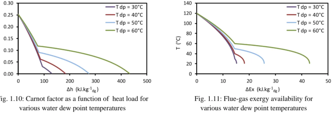
Calculation of the exergy availability allows the identification of the overall potential for electricity production of a given heat source. In order to identify the amount of energy available for conversion into work, the temperature is replaced by the Carnot-Factor (Fig. 1.10).
0
- 1 - m
Carnot Factor T T Eq. 1.7
m
T h s Eq. 1.8
The Carnot-Factor (Eq. 1.7) is calculated between the temperature at a given state and the ambient temperature (To). Fig. 1.10 shows the evolution of the Carnot-Factor over the heat load. In Eq. 1.8,
“Δh” and “Δs” are respectively the enthalpy and entropy difference and are calculated for a 1-K gas cooling. The surface under the graphs represents the exergy of heat sources. As the exergy is the work that could be extracted by a perfect cycle, it gives the maximum potential of electricity production from a heat source.
The exergy of a system (relative to the assumed reference environment) depends on system temperature, pressure, and composition; the first two contribute to thermo-mechanical exergy, and the effect of composition to chemical exergy. The mass exergy can be expressed as [LOZ 03]:
o.
i i.
i io T P
o,oi = CO ,O ,N ,H O
2 2 2 2
Ex
h T s
y
Eq. 1.9Where: subscript “o” refers to the specified reference state, “μ” is the chemical potential, and “y” is the mass fraction. The calculations show that the chemical exergy is less than 2% of the thermo-mechanical exergy and can be neglected. For more detail about the chemical exergy calculation, refer to” Annex A”.
0 20 40 60 80 100 120 140 0 100 200 300 400 500 T ( °C) ∆h (kJ.kg-1 dg ) T dp = 30°C T dp = 40°C T dp = 50°C T dp = 60°C
Chapter 1: Study and design of thermodynamic cycles for low-temperature heat sources 12
Fig. 1.10: Carnot factor as a function of heat load for various water dew point temperatures
Fig. 1.11: Flue-gas exergy availability for various water dew point temperatures
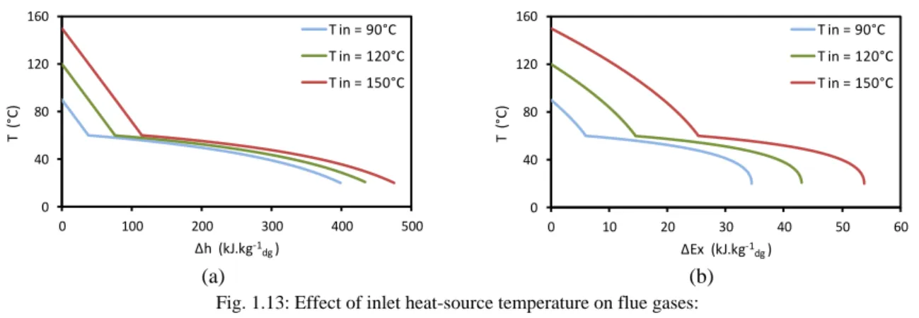
Fig. 1.11 illustrates the exergy availability for various water dew point temperatures. The exergy difference is calculated for a 1-K gas cooling. The same analysis as for Fig. 1.9 can be applied. As the exergy is the work that could be extracted by an ideal cycle [LAL 05], it is a good measurement to identify the overall potentials for electricity production of a heat source. The electricity that can be produced in a real process is of course lower than the available exergy.
(a) (b)
Fig. 1.12: Flue-gas histograms: a) heat load availability, b) exergy availability with and without water vapor condensation for various water dew point temperatures
The heat load and exergy availabilities are drawn Fig. 1.12.a and Fig. 1.12.b respectively. The blue parts represent the portion that could be extracted without water vapor condensation; the red parts account for the sensible and latent portion below water dew point.
Table 1.4 shows the values of the flue-gas heat load and exergy availabilities for various water dew point temperatures. Available heat loads with and without condensation are in the same range for a water dew point temperature of 40°C. The effect of water vapor condensation appears clearly at high water dew point temperatures. For a water dew point temperature of 60°C, the available heat load below it is around 4.7 times that above it and the available exergy below it is around 2 times that above it.
Table 1.4: Values of the flue-gas heat load and exergy availabilities for various water dew point temperatures Tdp (°C)
Heat load availability (kJ.kg-1dg) Exergy availability (kJ.kg-1dg)
Below water dew point
Above water dew
point Ratio
* Below water
dew point
Above water
dew point Ratio
*
30 39.1 94.3 0.41 0.7 14.5 0.05
40 99.8 86.9 1.15 3.7 14.5 0.26
50 197.4 80.7 2.45 11.3 14.4 0.78
60 360.7 76.1 4.74 28.5 14.5 1.97
*Ratio: heat load (resp. exergy) with- over- without water vapor condensation
0.00 0.05 0.10 0.15 0.20 0.25 0.30 0 100 200 300 400 500 Ca rn o t fa ct o r ∆h (kJ.kg-1 dg ) T dp = 30°C T dp = 40°C T dp = 50°C T dp = 60°C 0 20 40 60 80 100 120 140 0 10 20 30 40 50 T ( °C) ∆Ex (kJ.kg-1 dg ) T dp = 30°C T dp = 40°C T dp = 50°C T dp = 60°C 0 100 200 300 400 500 30 40 50 60 ∆h ( kJ .k g -1 d g ) T dp(°C)
Below water dew point Above water dew point
0 10 20 30 40 50 30 40 50 60 ∆E x ( kJ .k g -1d g ) T dp(°C) Below water dew point Above water dew point
Chapter 1: Study and design of thermodynamic cycles for low-temperature heat sources 13
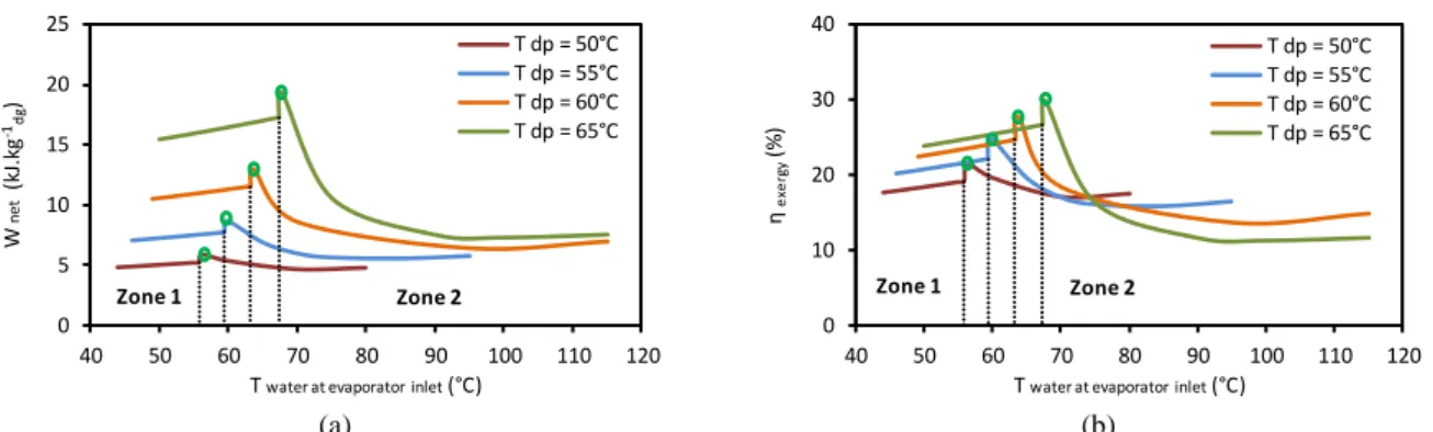
The effects of inlet heat-source temperature on both heat load and exergy availabilities are shown in Fig. 1.13.a and Fig. 1.13.b respectively, for a water dew point temperature of 60°C. The water dew point (60°C) is visible. As the inlet heat-source temperature increases, both energy and exergy recovered by sensible heat extraction increase while the latent heat remaining the same, which is obvious.
(a) (b)
Fig. 1.13: Effect of inlet heat-source temperature on flue gases: a) heat load availability, b) exergy availability (Tdp = 60°C)
1.2.2
Ideal overall and exergy efficiencies
The ideal overall efficiency is the maximal overall efficiency that can be reached into a conversion cycle; it is equal to the amount of energy available for transformation into work (exergy) over the maximal heat load released by the heat source by cooling it down to the ambient temperature (Eq. 1.10).
inmax
( - .s ) - ( - . )
-available in o out o out
overall ideal
in o
Ex h T h T s
Q h h Eq. 1.10
The ideal exergy efficiency is equal to the amount of energy available for transformation into work (exergy) over the maximal available exergy obtained by cooling down the heat source to the ambient temperature (Eq. 1.11).
inmax in
( - .s ) - ( - . )
( - .s ) - ( - . )
available in o out o out
exergy ideal
available in o o o o
Ex h T h T s
Ex h T h T s Eq. 1.11
Where in Eq. 1.10 and Eq. 1.11:
hin, hout: enthalpies of flue gases at inlet and outlet flue-gas temperatures respectively.
sin, sout: entropies of flue gases at inlet and outlet flue-gas temperatures respectively.
ho, so: enthalpy and entropy of flue gases at the dead reference state.
The ideal overall and exergy efficiencies over the heat source temperature are presented Fig. 1.14 and Fig. 1.15 respectively. These efficiencies are calculated for a 1-K gas cooling. The sudden breaks in slope indicate initial water dew points. As shown in Fig. 1.14, a maximal overall efficiency around 10% can be reached for a water dew point temperature above 40°C. As the water dew point increases, the overall and exergy efficiencies decrease in the sensible heat zone since an important heat load and exergy are released below the water dew point temperature.
0 40 80 120 160 0 100 200 300 400 500 T ( °C) ∆h (kJ.kg-1 dg ) T in = 90°C T in = 120°C T in = 150°C 0 40 80 120 160 0 10 20 30 40 50 60 T ( °C) ∆Ex (kJ.kg-1 dg ) T in = 90°C T in = 120°C T in = 150°C
Chapter 1: Study and design of thermodynamic cycles for low-temperature heat sources 14
Fig. 1.14: Ideal overall efficiency Fig. 1.15: Ideal exergy efficiency
The analysis carried in this section shows that the sensible energy could be recovered at relatively high temperatures compared to the latent energy. However, for the same change in flue-gas stream temperature, much higher quantities of energy are available below the water vapor dew point rather than above it.
After estimating the heat load and exergy availabilities of the low-temperature heat sources depending on their moisture content, the next step consists in reviewing the existing thermodynamic cycles adapted at low-temperature level (~ 120°C) in order to recover the heat-source energy via electricity production.
1.3 Power generation cycles
Generating power from waste heat typically involves using the waste heat to generate mechanical energy that then drives an electric generator. When considering power generation options for waste heat recovery, an important factor to keep in mind is the thermodynamic limitations on power generation at different temperatures. As discussed in §1.1.3.2, the efficiency of power generation is heavily dependent on the temperature of the waste heat source. In general, power generation from waste heat has been limited to only medium-to-high-temperature waste heat sources. However, advances in alternate power cycles may increase the feasibility of generation at low temperatures. While maximum efficiency at these temperatures is lower, these systems could still be economical in recovering large quantities of energy from waste heat.
The most frequently used system for power generation from waste heat involves using the heat to generate steam, which then drives a steam turbine. A schematic of waste heat recovery with a Rankine cycle is shown in Fig. 1.16. The pump supplies water to the evaporator, where water is heated and vaporized by the flue-gas heat stream. The generated high-pressure steam is expanded by the turbine, which is directly coupled to an electrical generator producing power, and then, the low-pressure vapor is condensed in a condenser. The traditional steam Rankine cycle is the most efficient option for waste-heat recovery with temperatures above 350°C. At lower waste heat temperatures, steam cycles become less cost effective, since pressure steam will require bulkier equipment. Moreover, low-temperature waste heat may not provide sufficient energy to superheat the steam, which is a requirement for preventing steam condensation and erosion of the turbine blades. Therefore, low temperature heat recovery applications are better suited for the “Organic Rankine Cycle (ORC)” or “Kalina Cycle” that use fluids with lower boiling point temperatures compared to steam [BCS 08].
0 2 4 6 8 10 12 0 20 40 60 80 100 120 140 ɳ ov er al l (% ) T (°C ) T dp = 30°C T dp = 40°C T dp = 50°C T dp = 60°C 0 20 40 60 80 100 120 0 20 40 60 80 100 120 140 ɳ ex er gy (% ) T (°C ) T dp = 30°C T dp = 40°C T dp = 50°C T dp = 60°C
Chapter 1: Study and design of thermodynamic cycles for low-temperature heat sources 15
Fig. 1.16: Waste heat recovery with Rankine Cycle [BCS 08]
1.3.1 Organic Rankine Cycle
The Organic Rankine Cycle (ORC) operates similarly to the steam Rankine cycle, but uses an organic
working fluid instead of steam. Options include HFC (R-245fa, R-152a,
R-1234yf…), and hydrocarbons (butane, isobutane, pentane…) that have a lower boiling point and higher vapor pressure than water. This allows the Rankine cycle to operate with significantly lower waste heat temperatures, sometimes as low as 60°C. The most appropriate temperature range for ORCs will depend on the fluid used, as the thermodynamic properties of the fluids will influence the cycle efficiency at various temperatures.
In comparison with water, the organic working fluids used in ORCs have a higher molecular mass, enabling compact designs, higher mass flow, and higher turbine efficiencies (as high as 80 to 85%). However, since the cycle operates at lower temperatures, the overall efficiency is only around 3 to 5%, depending on the temperature of the condenser and evaporator. While this efficiency is much lower than at high-temperature steam power plant (> 30%), it is important to remind that low-temperature cycles are inherently less efficient than high-temperature cycles [BCS 08]. Limits on efficiency can be expressed according to Carnot efficiency as shown previously (refer to Fig. 1.8).
1.3.2 Kalina Cycle
The Kalina cycle is a variation of the Rankine cycle, using a mixture of ammonia and water as the working fluid. A key difference between single fluid cycles and cycles that use binary fluids is the temperature profile during boiling and condensation. For pure fluid cycles (e.g., Steam or Organic Rankine Cycle), the temperature remains constant during boiling. As heat is transferred to the working medium (e.g. isobutane), the isobutane temperature increases to boiling temperature, at which point the temperature remains constant until all the liquid has evaporated. In contrast, a binary mixture of water and ammonia (each of which has a different boiling point) will increase its temperature during evaporation. This allows better thermal matching with the waste heat source and with the cooling medium in the condenser.
Configuration shown in Fig. 1.17 is a version of the Kalina Cycle [BEC 12]. In this cycle, a basic ammonia/water mixture is partially evaporated using the heat source and internal recuperation. The stream is then separated, where the ammonia-rich vapor is sent to the turbine and the ammonia-lean liquid is used for heat recovery before being injected at the turbine exhaust. This heat recovery maximizes the efficiency by cooling the source down to low-temperatures thanks to the temperature glide during the evaporation.
Chapter 1: Study and design of thermodynamic cycles for low-temperature heat sources 16
Fig. 1.17: Kalina Ammonia/Water Cycle [BEC 12]
The Kalina cycle is proven and operating in several geothermal and industrial heat sources. However, many studies report that the use of ORC instead of Kalina cycle is more promising at low temperature level (~ 120°C). As reported in Bombarda et al. [BOM 10], the adoption of Kalina cycle for low-temperature heat sources seems not to be justified, as the gain in performance with respect to a properly optimized ORC is very small and must be obtained with a complicated plant scheme, large surface heat exchangers, and particularly high-pressure resistant and no-corrosive materials. In addition, in the report, using a well-defined blend working fluid for ORC at low-temperature heat source could be more advantageous than Kalina cycle, which uses ammonia-water mixture as working fluid.
After reviewing the main existing thermodynamic cycles adapted at low-temperature level (~ 120°C), the next step consists in reviewing the main heat-exchange recovery technologies to extract heat from low-temperature heat sources depending on their moisture contents.
1.4 Low-Temperature Heat Exchange
As stated previously, industrial flue gases may contain significant amount of water vapor associated to many processes such as flashing, washing, cleaning, and drying. Therefore, a considerable amount of heat is available in the form of water latent heat of condensation and cannot be recovered if flue gases are not cooled down to temperatures lower than the water vapor dew point. This low-temperature heat recovery leads to significant benefits, provided the acid corrosion problems can be overcome in a cost-effective way. The benefits include increased turbine power and credit for reduced emissions of sulfuric and nitric acids. Technologies are available that can cool gases below water dew point temperatures to recover low-temperature waste heat. Main options include indirect contact water-vapor condensation recovery and direct contact water-water-vapor condensation recovery.
1.4.1 Indirect Contact Water-Vapor Condensation Recovery
In an indirect contact water vapor condenser, the heat is transferred between the two fluids (typically flue gases and working fluid) using an intervening wall (typically fin-and-tube heat exchanger). The indirect contact condenser recovery could be used to recover energy from heat sources either with low or high-moisture contents. In the latter, the heat-exchanger design requires using specific materials such as stainless steel, or advanced materials such “Teflon”, “Epoxy” or equivalent coating to withstand exposure to corrosion problems when cooling the gas below the water vapor dew point temperature.
Chapter 1: Study and design of thermodynamic cycles for low-temperature heat sources 17
1.4.2 Direct Contact Water-Vapor Condensation Recovery
Direct contact condensation recovery involves direct mixing of the process stream (flue gases) and cooling fluid (typically water) (Fig. 1.18). Since these systems do not involve a separating wall across which heat must be transferred, they avoid some of the challenges of large heat-transfer surfaces required for indirect contact units. The direct-contact heat exchanger has received attention because there are no heat-transfer surfaces exposed to corrosion, clogging, and fouling.
A challenge with direct-contact condensation is that the water can be contaminated by substances in the flue gases. A water treatment system should be provided in order to ensure that the water is cleaned before being re-used for another heat extraction cycle. The use of the direct-contact condenser makes sense when recovering energy from heat sources with high-moisture contents.
Fig. 1.18: Heat recovery using direct contact condensation (Condensing Unit) [BCS 08]
1.4.3 Transport Membrane Condenser
Transport Membrane Condensers (TMCs) are a developing technology for capturing water (along with water’s latent heat) from the water vapor in gas exhaust streams. Water is extracted from flue gases at temperatures above water dew point by employing capillary condensation. A schematic of the TMC in operation is shown Fig. 1.19.Like direct-contact heat-recovery units, TMCs extract hot water directly from the flue gases; however, since TMCs recover the water via transport through a membrane, the recovered water does not become contaminated as in a direct-contact unit. The technology has been demonstrated for clean exhaust streams in a natural gas-fired boiler; however, TMCs require more research in advanced materials before widespread implementation for dirtier waste streams is possible. Needed areas of research & development for enhancement include TMC strength and resistance to contaminants.
Chapter 1: Study and design of thermodynamic cycles for low-temperature heat sources 18
After reviewing the main existing thermodynamic cycles adapted at low-temperature level (~ 120°C) and the heat recovery technologies, the next step consists in the study and optimization of the thermodynamic cycles for recovering low-temperature heat sources by optimizing the net power produced. The study will be based on the well-proven Organic Rankine Cycle (ORC). The two main water-vapor condensing heat recovery modes will be investigated: direct and indirect water vapor condensation.
Many investigations were carried out about heat recovery using ORC. Comprehensive researches on appropriate working fluids for low-temperature applications have been investigated by many authors such as [DAI 09], [HUN 97], and [LIU 04]. Others researchers have focused on the parametric optimization and performance analysis of the ORC like [ROY 10], [ROY 11a], [WEI 07], [ROY 11b], and [ROY 12]. However, these studies deal with the indirect-contact condensation recovery based on sensible heat extraction from flue gases with low-moisture contents. The originality of the following work is to extend the ORC applications to low-grade gas heat sources with high-moisture contents by pointing out the effect of water vapor condensation on cycle performance using the two condensing heat recovery processes (direct and indirect heat exchange).
For this purpose, several ORC configurations will be analyzed and optimized:
Simple ORC with indirect-contact condensation heat recovery
Simple ORC with direct-contact condensation heat recovery
Two-stage ORC
Trans-critical ORC
1.5 Simple ORC with indirect-contact heat recovery
1.5.1 Simple ORC with direct evaporator
1.5.1.1 Parameters of the simple ORC
The simple ORC is called “direct evaporator cycle” when flue gases heat directly the ORC working fluid in the evaporator without using a heat-transfer medium.
(a) (b)
Fig. 1.20: Simple ORC: a) layout diagram, b) (T-s) diagram
The layout diagram of a simple ORC is presented Fig. 1.20. The ORC system consists of an evaporator, a turbine, a condenser, and a pump. As shown in Fig. 1.20, the pump supplies the working fluid to the evaporator, where the working fluid is heated and vaporized by the flue-gas heat stream (Point i). The generated high-pressure (Point 3) vapor is expanded by the turbine, which is directly coupled to an electrical generator producing power, and then, the low-pressure vapor is condensed in a
i e Condenser Turbine Generator Pump Evaporator 1 2 3 4 3 e i DT 2 2a 2b 4b 4a 1 Pcond Pevap Entropy [kJ/(kg.K)] Tem p era tu re [K ] 4s 4 2s