OATAO is an open access repository that collects the work of Toulouse
researchers and makes it freely available over the web where possible
Any correspondence concerning this service should be sent
to the repository administrator:
tech-oatao@listes-diff.inp-toulouse.fr
This is an author’s version published in: http://oatao.univ-toulouse.fr/26902
To cite this version:
Rakotondrabe, Micky
and Kumari, Neetu A Hybrid
vibrational-thermal harvesting using a closed system based on lead free
piezoelectric materials for constant temperature condition. (2020)
In: COMSOL Conference 2020 Europe, 14 October 2020 - 15
October 2020 (Online Event, Unknown).
A Hybrid vibrational-thermal harvesting using a closed system
based on lead free piezoelectric materials for constant temperature
condition
Neetu KUMARI 1,* and Micky RAKOTONDRABE 2
1Ph.D. Researcher, FEMTO-ST Institute, University of Bourgogne Franche-Comte - CNRS, Besancon, France ,2Laboratoire Génie de
Production, National School of Engineering in Tarbes (ENIT-INPT), University of Toulouse * neetu.kumari@femto-st.fr,*mrakoton@enit.fr
Abstract:
Within the ENHANCE European project, hybrid energy harvesters have to be designed and developed to supply small and autonomous sensors in automobiles. The focus of this work is particularly related to the harvesting of energy from the vibration of the vehicle and from the high temperature (in fluctuation or not) around the engine. To this aim, an ideal hybrid energy harvester should be able to harvest vibrational energy at lower frequency ranges (>500 Hz) and pyroelectric energy at a higher temperature range. However, pyroelectric effect work with a time-varying temperature. Furthermore, the use of lead based piezoelectric materials as usual creates an environmental concern due to lead-toxicity.
In this paper, a hybrid energy harvester has been designed using Lithium Niobate piezoelectric material, shape memory alloy, polyvinyl difluoride, piezoelectric polymer and helium gas, and its performance has been investigated using COMSOL Multiphysics® finite element method (FEM) software for rapid validation of the proof of concept and for visualization of the transducer functioning. The proposed hybrid harvester is capable of converting both vibrational mechanical energy and constant temperature energy into electrical energy. The principle behind the constant temperature conversion is based on the Joule-Thomson physical principle. Different transducer design and material configurations have been evaluated to identify the optimum conditions, materials, and design of the hybrid transducer. For the FEM analysis, Solid mechanics, electrostatics for piezoelectricity, heat transfer in solids, heat transfer in fluids, electric currents chemistry modules have been used for pyro electricity and associated thermodynamic properties in global definitions as well as for the vibrational piezoelectricity. The simulation demonstrates that the hybrid harvester was able to generate energy the constant temperature, as predicted. The harvester has a volume of 12.21 cm3 and can
work at a constant temperature between 20 and220 °C, and surrounding mechanical vibration 0- 500 Hz of frequency. On the one hand, the harvester was able to work for up to 8 hours under constant temperature. On the other hand, the calculated stored energy was 8.92 µJ at 261Hz of mechanical vibrational excitation. This lead-free piezo-pyro energy harvester is a promising device, which can be used for environmental purposes, especially in automobiles. Its high-temperature performance stability, energy harvesting at constant external temperature, piezoelectric energy harvesting at lower frequencies, and lead-free nature make it an ideal to be used as energy harvester and supplier for small appliances.
Keywords: Energy Harvesting, Piezoelectric, Pyroelectric, Finite element analysis, COMSOL.
1. Introduction
We can say that Energy harvesting is promising and upcoming replacement for batteries [1]. In our surrounding, we can find various forms of energies are present and among them the most common one is the waste heat and vibrational one, which many processes produce and therefore, which makes them a promising source for energy harvesting technology, and various methods have been proposed. If we talk about the waste heat and how we can use it then we have to mention the thermoelectric generators, which are based on the See beck effect, have been widely researched [2]. Nevertheless, the more people studied more they explored about it and they discovered some drawbacks related to the efficiency of these generators as figure of merit was one of the limiting factor for the thermoelectric materials, ZT. Due to this reason, pyroelectric materials gained all the attention, which has high conversion efficiency, moreover pyroelectric materials have the pyroelectric effect with spontaneous polarization [3, 4].However working with pyroelectric materials is also quite challenging, as the pyroelectric energy harvesting works on the temporal temperature oscillation which means that you have to establish a time varying temperature in the system. In the past, few years many people have worked on thermal systems like S. K. T. Ravindran et al. developed an engine chamber with sealed air and a bistable membrane [3]. Miwon Kang et al. studied the thermal Energy Harvesting Using Pyroelectric and Piezoelectric Effect based on a bimetallic beam structure [4], and Marcel Gueltig et al. adapted magnetic shape memory alloy films [5]. A. Ibragimov et.al developed a micro machined membrane based heat engine as an electrostatic power generator where he encapsulated a liquid-gas mixture inside a closed chamber and the thermal energy flowing through the chamber causes the pressure changes according the cycles of the heat engine and thus cyclically moves the flexible chamber’s wall [6] In this paper, we tried to implement a similar concept of closed system like A. Ibragimov but instead the used of liquid-gas mixture we have used helium gas the reason for using it is illustrated in the coming section the closed system or we can say a throttling device which works on the concept of joule-Thompson effect where we can see the change in temperature occurs when a gas is encapsulated inside a closed
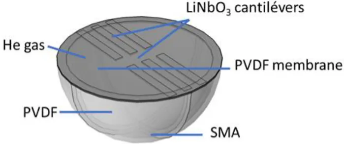
boundaries with the opening is closed with a flexible membrane due to which the throttling will appear. Joule-Thomson cooling is the name given to the drop in temperature that occurs when a real gas such as CO2 or N2 expands from high pressure to low pressure at constant enthalpy (i.e., adiabatic expansion) the gas exceptions to this cooling upon expansion effect are Hydrogen, Helium and Neon, which actually heat up. Here, a temperature change is necessarily desirable. As this system will be working as a hybrid system where we would like to harvest both the vibrational and thermal energies, we decided to use lithium Niobate as it is a lead free materials, which is primary aim of this work, moreover it shows both the pyroelectric and piezoelectric effects, which makes it a perfect choice for our work Figure 1 illustrates the proposed concept. It is assumed that this closed system will be vibrating at 1 g of acceleration, for the Thermal gradient we are going to follow the joules Thompson effect where the temperature of the gas will simultaneously changes over time. The structure consist of a hemisphere made up of copper and a circular ring consists six cantilevers are attached on the top and sealed with a PVDF film.
Figure 1. Illustration the proposed Hybrid concept
This paper is organized as follows. Section I presents the research motivation for hybrid energy harvesting devices. Section II describes the theoretical operation of closed hybrid energy harvesting device and the design of the proposed energy harvester. The simulation of the proposed energy harvester for closed system working at a constant temperature is explained in Section III. Simulation results and analysis results are presented and discussed in Section IV. Finally, concluding remarks are made in Section V.
2. Hybrid Energy Harvesting Design
A model of the proposed Hybrid energy-harvesting device is presented; along with the equations for the piezoelectric effect here, we have described the pyroelectric effect as well along with that, we have presented a detailed version of joules Thompson effect. This model is also used to estimate the resonant frequency. The system is modeled as a 1 degree-of-freedom (DOF), spring-mass damper system. This model is configured as a base excitation, since it represents a device with a solid outer structure (black rectangle) that is shaken by an external acceleration (𝑋̈(𝑡)). According to modal analysis theory, the governing equations for such a piezoelectric EH system can be written as [8]:
𝑚𝑥̈1(𝑡) + 𝐶𝑋̈1(𝑡) + 𝐾𝑋1(𝑡) + 𝑓𝑒(𝑡) = 𝑚𝑋(𝑡)̈ (1)
Where m, C, and K are the effective mass, mechanical damping, and stiffness, respectively fe is the effective force due to the piezoelectric element; 𝑋 (𝑡) is the acceleration applied to the housing due to external ambient vibration from the environment, and X1(t) is the mechanical displacement of the proof mass. The effective transducer force fe can be presented
as [8]:
𝑓𝑒= 𝑘𝑚 𝑉𝑝 (𝑡) (2)
𝑘𝑚𝑋1(1) − 𝐶𝑝𝑉𝑝(𝑡) = 𝑄𝑝(𝑡) (3)
Where 𝑘𝑚 is the effective electromechanical coupling
coefficient of a piezoelectric structure; VP (t) and QP (t) are the voltage across the piezoelectric electrodes, and the charge generated on the electrodes; Cp is the capacitance of the piezoelectric material. The main goal here in piezoelectric part is to convert the ambient vibration energy into electrical power. Several design iterations were done whereby the design was simulated by COMSOL. The cantilever-beam structure with proof-mass was found to be the simplest oscillator design that could meet the objectives for our design. A cross-sectional diagram of the proposed configuration is illustrated in Figure 2
Figure 2. Models of single DOF vibration based energy harvester.
In the model for the pyro part, we can say that Pyro electricity is a coupled effect that relates a change in temperature to a change in electrical displacement D (with units of C/m2), 𝑑𝐷 = 𝑝𝑑𝜃 (4) Where p is the pyroelectric coefficient (with units of C/m2.K). Both displacement and the pyroelectric coefficient are vectors or first-rank tensors. The pyroelectric coefficient is defined by 𝑝 = (𝜕𝑃𝑆/𝜕𝜃) σ, E. (5)
Where the constraints are constant electric field E, and constant elastic stress σ.
When talking about energy harvesting from heat, we need first to establish the equations of pyroelectric materials [9]. It is assumed here idealized pyroelectric materials exhibiting no losses and purely linear properties.
𝑑Ӷ = 𝑝𝑑𝐸 + 𝐶𝐸 𝑑𝜃
𝜃 (7)
Where D, E, θ, and Γ are electric displacement, electric field, temperature, and entropy, respectively. The coefficients are defined as: 𝜀33𝜃 = ( 𝑑𝐷 𝑑𝐸) 𝜃, 𝑃 = 𝑑𝐷 𝑑𝜃= 𝑑Ӷ 𝑑𝐸, 𝐶𝐸= ( 𝑑𝑈 𝑑𝜃)𝐸 (8)
Where U is the internal energy. εθ
33, p, CE, are the dielectric
permittivity, pyroelectric coefficient and calorific capacity, respectively.
Analogizing to electromechanical case in the work of Lefeuvre, the harvested power in the pyroelectric case can be defined as;
𝑃𝑚𝑎𝑥= 𝑝2𝜃2
2𝜋𝜀33𝜃 (9)
To understand better, how the joule Thompson effect will take we did mathematical modelling for that as well,
We can say we assumed that it would be an adiabatic throttling process by this we imply that there will be no exchange or heat or mechanical work will take place with the environment. As we are assuming that there will be no change in temperature is happening in the surroundings i.e. ΔT = 0. However keeping in
mind that there will be always vibration is present in the system.
After this, we focused on the fundamental thermodynamics to develop an energy balance inside the closed system.
Keeping in mind the thermodynamics is the study of systems involving energy in the form of heat and work. A good example of a thermodynamic system is gas confined by a piston here we have a flexible membrane in the closed system. If the gas is heated, it will expand, doing work on the piston; this is one example of how a thermodynamic system can do work. Thermal equilibrium is an important concept in thermodynamics. When two systems are in thermal equilibrium, there is no net heat transfer between them. This occurs when the systems are at the same temperature. In other words, systems at the same temperature will be in thermal equilibrium with each other.
The first law of thermodynamics relates changes in internal energy to heat added to a system and the work done by a system. The first law is simply a conservation of energy equation:
dU = dQ − dW (10) The first law of thermodynamics relates the change in internal energy dU to the work dW done by a system and the heat dQ added to it.
By definition, in an adiabatic process, the heat exchanged dQ = 0. Substituting this in the first law and rearranging gives 0 = dQ = dU + dW (11) The second term is easy: the work done dW when a system changes its volume V by dV is PdV.
The first term may be related to the specific heat, which is defined as the heat added per unit temperature change per mole of substance. If we add heat at constant volume, then the gas does not expand and so does not do work. Therefore, the added heat increases the internal energy U. The specific heat at
constant volume can be written as [cv = ((𝑑𝑈
𝑑𝑡)𝑣) ] and n is the number
of moles. Hence
𝟎 = 𝒏𝒄𝒗 𝒅𝑻 + 𝑷𝒅𝑽 (12)
Now the equation of state of an ideal gas is
nRT = PV (13) Where R is the gas constant. Taking derivatives gives 𝒏𝑹𝒅𝒕 = 𝑷𝒅𝑽 + 𝑽𝒅𝑷 (14)
We may now combine equations (12) and (13) to eliminate T. (12) and (13) give respectively these expressions for ncv dT: −𝑷𝒅𝑽 = 𝒏𝒄𝒗𝒅𝑻 =
𝒄𝒗
𝑹(𝑷𝒅𝑽 + 𝑽𝒅𝑷) (15)
Collecting the PdV and VdP terms gives 𝟎 = (𝟏 +𝒄𝒗 𝑹) 𝑷𝒅𝑽 + 𝒄𝒗 𝑹𝑽𝒅𝑷 (16) 𝟎 =𝑹+𝒄𝒗 𝒄𝒗 . ( 𝒅𝑽 𝑽) + ( 𝑫𝑷 𝑷) (17)
Now if the gas is ideal, then dU = n cv dt And if some work is
done by a gas adiabatically, then heat change will be zero then in this situation we can have two cases: 1) Expansion occurs at the cost of internal energy of the gas and so gas temperature falls as the gas expands. So, internal energy decreases. Or, 2) As the temperature falls, the velocity of the gas molecules deceases too which then consecutively lowers the kinetic energy of the gas. From the equation of state of an ideal gas (12), we can calculate the work dW done at constant pressure: it is just PdV = nRdT.
So the specific heat of an ideal gas at constant pressure is just
cP = cv + R. and the ratio of specific heats is given a standard
symbol 𝜸 = 𝒄𝒑/𝒄𝒗. Therefore, we have 𝟎 = 𝜸 (𝒅𝑽 𝑽) + ( 𝒅𝑷 𝑷) (18)
Hence for an adiabatic process in an ideal gas,
𝑷𝑽𝜸 = 𝒄𝒐𝒏𝒔𝒕𝒂𝒏𝒕 (19)
While keeping in mind that cP > cV : At constant volume, all
the heat you put in goes to increasing the internal energy and thus raising the temperature. At constant pressure, you need to put in not only the heat that raises the internal energy, but also an amount of heat equal to the work done when the system undergoes thermal expansion. For gas filled inside the system, helium γ is about 1.3.
Of course, we may now substitute into (19) from the equation of state (13) to see how P and T or T and V are related for an adiabatic process.
Now focusing on the joules Thompson effects
The classic Joule Thomson expansion consists of a thermally insulated system with gas on one side initially at p1, V1, and T1 that flows through a porous plug and out the other side at p2, V2, and T2. In the absence of heat exchange with the surroundings, the total work done by the expanding gas equals the change in internal energy which is given by
𝒘 = ∆𝑼 = 𝑷𝟏𝑽𝟏− 𝑷𝟐𝑽𝟐 (20)
For an ideal gas, p1V1 = p2V2 and the Joule-Thomson
Expansion would be at constant internal energy. However, Our interest is in helium as it’s not an ideal gas but the closest one among the other gases when it comes to show the throttling effects. The change in enthalpy of the system in the Joule-Thomson expansion is given by
∆𝑯 = ∆𝑼 + ∆(𝒑𝑽) (21) Upon substitution of Eq. (20) into Eq. (21), we have
∆𝑯 = 𝟎 (22)
i.e., the Joule-Thomson expansion is at constant enthalpy. It can be observed that when the Joule-Thomson expansion is carried out for a number of different pressure drops (dP) across the porous plug or in our case the flexible membrane different dT’s are measured, that a plot of dT vs. dP is approximately linear with a slope equal to the Joule-Thomson coefficient (
µ
JT):
∆𝑻
∆𝑷= (
𝝏𝑻
𝝏𝑷) 𝑯 = 𝝁𝑱𝑻 (23)
For doing the modelling we have assumed that
µ
JT is negative(i.e., expansion leads to heating). However, the sign of
µ
JT canalso be positive (i.e., meaning the gas cools down upon expansion). The so-called Joule-Thomson inversion temperature for a particular gas, gas will heat upon expansion, whereas below the inversion temperature it will cool. At room temperature, common gases such as CO2, N2, and O2 cool upon expansion while He and Ne warm upon expansion. That is also another reason that made such choose helium. Table 1 lists the final design parameters of the proposed closed system.
Table 1: Design parameters for the closed system Design Parameter Description Design Value [units] Radius of the hemisphere Material: shape memory alloy 1.8 cm Thickness of the Hemisphere Material: shape memory alloy 0.05 cm Dimension of the middle two Cantilever Material: lithium Niobate 1.3×0.05× 0.035 [𝐿 × 𝑊 × 𝐻] cm Dimension of the outer four Cantilever Material: lithium Niobate 1.25×0.05× 0.035 [𝐿 × 𝑊 × 𝐻] cm Dimension of the middle two Cantilever Material: Nitinol 1.3×0.05× 0.015 [𝐿 × 𝑊 × 𝐻] cm Dimension of the middle two Cantilever Material: Nitinol 1.3×0.05× 0.015 [𝐿 × 𝑊 × 𝐻] cm Thickness of the membrane Material: PVDF 0.05 [πr2] cm
3. Use of COMSOL for closed system
A computer model is developed to simulate the performance of the closed system design as specified in Figure 1 and Table 1. The COMSOL Finite Element Analysis (FEA) package is used to estimate the closed system performance, using four different studies. A vast simulation is carried out; the model is simulated with 3-D (three-dimensional) analysis. In order to guarantee mesh integrity, the aspect ratio of individual mesh elements should not be greater than three [12]. Figure 2(a), (b) illustrates the plot of the quality mesh of the closed system, internal COMSOL mesh quality analysis showed the mesh to be of high quality. With the help of developed FEA model, three different studies are done to investigate the performance: (1) An Eigen frequency Study to determine the first Eigen frequency (resonant) and its mode shape for all the six cantilevers,
Figure 2: Mesh quality of the closed system (A) Side view (B) Top view
(2) A Stationary Study to check the total displacement and corresponding stress of the system due to gravity alone, in a static analysis, and (3) A Time Dependent Study Temperature distribution is simulated using Comsol Multiphysics since heat transfer and distribution are a critical factor in this study . 3.1 Eigen frequency Study
The closed system design is analyzed to determine its resonant frequencies by using FEA to find the Eigen frequencies and mode shapes of the structure. This analysis is extensively used during the geometrical design of the closed system. The first Eigen frequencies of all the six cantilevers are calculated and represented in Figure 3. The calculated values were a) 261 Hz, b) 284 Hz, c) 354 Hz, d) 440 Hz, e) 484 Hz, and f) 561 Hz
Figure 3. Eigen frequency study of all the six cantilevers.
3.2 Stationary Study
A static FEA analysis is done to determine the distribution of temperature inside the closed system. Figure 4 shows the result when the temperature increases from 19 ◦C of the heat reservoir to 25 ◦C of through the gas compression and joules Thompson effect at a stationary condition.
Figure 4. Simulation of temperature distribution
3.3 Time depending study
The model consists of heat transfer and laminar flow module. Heat transfer in solids in the heat transfer module was used. The time-dependent energy equation is as follows:
𝑑𝑧𝜌𝐶𝑝 𝜕𝑇
𝜕𝑡+ 𝑑𝑧𝜌𝐶𝑝𝑢. ∇𝑇 + ∇𝑇. 𝑞 = 𝑑𝑧𝑄 + 𝑞0+ 𝑑𝑧𝑄𝑡𝑒𝑑 (24)
Where ρ is the density (kg/m3), C
p is the heat capacity
(J/(kg·K)), T is the absolute temperature (K), u is the velocity (m/s), Q is the power density (W/m3), Q
ted and the
thermoelastic damping. q Represents the heat flux vector. 𝑞 = −𝑑𝑧𝑘∇𝑇 (25)
Where k is the thermal conductivity (W/(m · K)). This is Fourier’s law of heat conduction. The laminar flow module is based on Navier-Stokes equations as follows:
𝜕𝜌 𝜕𝑡+ ∇. (𝜌𝑢2) = 0 (26) 𝜌𝜕𝑢2 𝜕𝑡 + 𝜌(𝑢2. ∇)𝑢2 = ∇. [−𝑝𝐼 + 𝜇(∇𝑢2 + (∇𝑢2) 𝑇)) − 2 3𝜇(∇. 𝑢2)𝐼] + 𝐹 + 𝜌𝑔 (27)
Where u2 is the velocity (m/s), p is pressure (Pa), I is the unity tensor, µ is the dynamic viscosity (Pa·s), F is the volume force vector (N/m3), g is the acceleration of gravity. Equation (26) is the continuity equation and represents the conservation of mass, and Equation (27) represents the conservation of momentum. Figure 5 shows the Simulation of temperature distribution with respect to time in order to calculate the change in temperature over the cantilevers.
Figure 5 shows the Simulation of temperature with change in time.
3. Results and Discussion
The simulation results of the proposed closed system design are analyzed and discussed. The simulation demonstrates the plausibility of the introduced Heat Engine’s concept in energy harvesting by combining the Piezoelectric effect with
pyroelectric effect where the pyroelectric materials itself work on the principle of the heat engine. We combined different modules for our study like the solid mechanics and electro statics with the heat transfer module with solid and fluid along with the laminar flow we assumed the behavior of the gas to be compressible and after that to study the coupling effect of theses we used the Multiphysics modules where we used the
Piezoelectric effect with the non- isothermal flow, we did the study of the frequency, Eigen frequency and the time
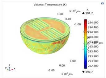
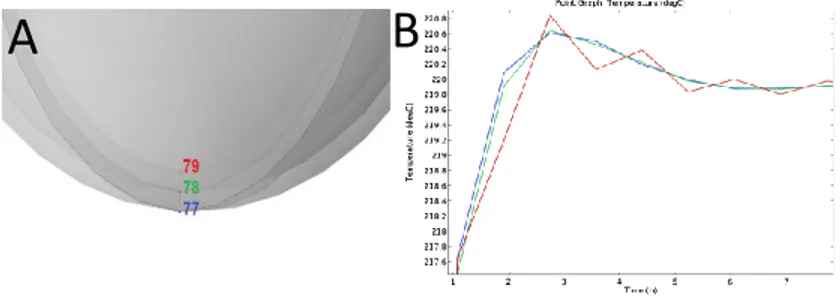
dependent, by combining these modules and defining the heat flux conditions in the solid and fluid and making the outer surface temperature as constant we can see in Figure 6,that the temperature of the gas is keep on fluctuating even when there is no heat source. By comparing the temperature in Figure 3. A) From the outer surface to the inner surface (Gas), in red is the gas temperature shows the maximum temperature change in temperature.
Figure 6. Shows the change in temperature of the gas inside the closed system.
After that, we also calculated the stored energy by the closed system, which we can say, was mainly done with the lead free material Lithium Niobate. Figure 7. Shows the total stored with respect to frequency. The simulations were carried out at 1 g of acceleration, as there will be continuous vibration in the system. Moreover we were able to calculate the fluctuation of the temperature of gas and able to conclude that the gas temperature will fluctuate for eight hours even when there is no natural conduction or external heating source is present.
Figure 7. Shows the total stored with respect to frequency.
Conclusions
The proposed closed system is designed to harvest two different sources of energy together as a hybrid system, but the main aim was to harvest the thermal energy at constant temperature as all
the pyroelectric materials needs a thermal gradient for them to generate electricity. But keeping in mind that the fabrication of such devices are very difficult as encapsulating gas inside and sealing it itself is a big challenge so for future work we would be focusing more on the experimental part and will try to validate the results we got from the comsol simulation with the experimental one.
References
1. Mitcheson P D, Yeatman E M, Rao G K, Holmes A S, Green T C, Proc. IEEE 96 (9), 2008, 1457-1486
2.Kiziroglou M E, Wright S W, Toh T T, Mitcheson P D, Becker Th, and Yeatman E M, IEEE Transactions on Industrial Electronics, 61, 1, 2014, pp. 302-309
3.Ravindran S K T, Huesgen T, Kroener M, and Woias P, Applied Physics Letters 99, 104102 (2011)
4. Miwon Kang and Eric M. Yeatman Thermal Energy Harvesting Using Pyroelectric and Piezoelectric Effect. 5.Gueltig M, Ossmer H, Ohtsuka M, Miki H, Tsuchiya K, Takagi T, and Kohl M, Adv. Energy Mater., 4, 2014, 140075 6.Fu H and Yeatman E M, Applied Physics Letters 107, 243905 (2015)
7. A. Ibragimov, H. Kesuma, M. Hormann, M. Trabelsi and W. Lang Conference: Proceed𝐴 = 𝜋𝑟2
ings of PowerMEMS 2011 8. M. Zhu, E. Worthington, and J. Njuguna, Analyses of Power Output of Piezoelectric Energy-Harvesting Devices Directly Connected to a Load Resistor Using a Coupled Piezoelectric-Circuit Finite Element Method, IEEE Transactions on Ultrasonics, Ferroelectrics, and Frequency Control, 56, pp. 1309-1318, 2009.
9. G. Sebald, E. Lefeuvre, and D. Guyomar. Pyroelectric energy conversion: optimization principles. IEEE Transactions on Ultrasonics, Ferroelectrics, and Frequency Control, vol.55, 538-551 (2008).
10. E. Lefeuvre, A. Badel, C. Richard, L. Petit, and D. Guyomar. A comparison between several vibration-powered piezoelectric generators for standalone systems. Sensors and Actuators A, Physical, vol.126, 405–416 (2006).
11. G. Sebald, L. Seveyrat, D. Guyomar, L. Lebrun, B. Guiffard, and S. Pruvost. Electrocaloric and pyroelectric properties of 0.75Pb (Mg1/3Nb2/3)O3–0.25PbTiO3 single crystals. Journal of Applied Physics vol.100, 124112 (2006). 12. B. M. Badr, K. R. Delaney, and N. Dechev, Design of a Low Frequency Piezoelectric Energy Harvester for Rodent Telemetry, Journal of Ferroelectrics, 481, pp. 98-118, Sep. 2015.
Acknowledgements
This project has been supported by the European ITN Marie Curie ENHANCE project. Members of MACS research group at AS2M/FEMTO-ST are also acknowledged for their kind support as well as the Mechanical department of FEMTO-ST for some experiments. The authors are also grateful to the members of PRIMES center of technology and LGP laboratory, both of ENIT-INPT, for the support to extensive experimental works a part of which was also supported by the national ANR CODE-TRACK project.
![Table 1: Design parameters for the closed system Design Parameter Description Design Value [units] Radius of the hemisphere Material: shape memory alloy 1.8 cm Thickness of the Hemisphere Material: shape memory alloy 0.05 cm Dimensio](https://thumb-eu.123doks.com/thumbv2/123doknet/2939186.78943/5.918.485.866.56.361/parameters-parameter-description-hemisphere-thickness-hemisphere-material-dimensio.webp)