OATAO is an open access repository that collects the work of Toulouse
researchers and makes it freely available over the web where possible
Any correspondence concerning this service should be sent
to the repository administrator:
tech-oatao@listes-diff.inp-toulouse.fr
This is an author’s version published in:
http://oatao.univ-toulouse.fr/24134
To cite this version:
Berrada, Nawal and Desforges, Alexandre and Bellouard, Christine and Flahaut,
Emmanuel
and Gleize, Jérôme and Ghanbaja, Jaafar and Vigolo, Brigitte
Protecting Carbon Nanotubes from Oxidation for Selective Carbon Impurity
Elimination. (2019) Journal of Physical Chemistry C, 123 (23). 14725-14733.
ISSN 1932-7447
Protecting Carbon Nanotubes from Oxidation for Selective Carbon
Impurity Elimination
Nawal Berrada,
†Alexandre Desforges,
†Christine Bellouard,
†Emmanuel Flahaut,
‡Jérôme Gleize,
§Jaafar Ghanbaja,
†and Brigitte Vigolo
*
,††Institut Jean Lamour, CNRS-Université de Lorraine UMR 7198, Campus Artem, 2 allée André Guinier, 54011 Nancy, France ‡CIRIMAT, Université de Toulouse, CNRS, INPT, UPS, UMR CNRS-UPS-INP 5085, Université Toulouse 3 Paul Sabatier, Bât.
CIRIMAT, 118, Route de Narbonne, 31062 Toulouse Cedex 9, France
§Laboratoire de Chimie Physique-Approche Multi-échelle de Milieux Complexes-University of Lorraine, 1 Bd Arago, 57078 Metz,
France
*
S Supporting InformationABSTRACT: Purity of carbon nanotubes (CNTs) is essential to avoid a dramatic decrease in their performances. In addition to metallic impurities, carbonaceous impurities have been shown to be responsible for pronounced effects. However, they are highly difficult to be selectively removed from CNT samples because of the similar chemical reactivity of these two kinds of carbon species. The existing purification methods often lead to high CNT consumption (>90 wt %). The proposed method consists of a one-pot gas-phase treatment combining chlorine and oxygen. The CNT powder maintained in a chlorine stream is submitted to oxygen at moderate temperature [350 and 500 °C for
single-walled CNTs (SWCNTs) and double-walled CNTs (DWCNTs), respectively], and the thermal treatment is then pursued at 900−1000 °C under chlorine alone. Our work reveals that this approach is able to significantly improve the selectivity of elimination of carbonaceous impurities. Thanks to the proposed purification treatment, only 19 and 11 wt % of carbon species (mainly carbon impurities) are lost for DWCNTs and SWCNTs, respectively. The mechanism proposed involves a protective effect by grafting of chlorine favored to the CNT walls. Because our simple one-pot purification method is also versatile and scalable, it opens new perspectives for CNT applications in high-added value fields.
1. INTRODUCTION
Carbon nanomaterials, such as carbon nanotubes (CNTs) and graphene, are exciting materials showing a combination of superior properties: lightness, thermal and electrical con-ductivity, and optical and mechanical properties.1 The technology of CNT synthesis, although in a continuous state of improvement, cannot avoid the use of catalysts to increase the conversion rate from carbon precursors to the production of carbon nanomaterials, as this rate is still far below 100%.2−6 The presence of both metal and carbon impurities has negative effects on the CNT properties.7,8 It is widely known that magnetic properties of CNTs are dominated by catalyst residues even at low content.9 Thermal and electrical conductivity and mechanical properties (tensile strength) are dramatically decreased because of carbon impurities in CNT samples.10 Although it was first attributed to the CNTs themselves, the observed electrocatalytic activity has been shown to be due to metallic catalyst impurities11,12 or carbonaceous by-products.13−15 Similar mistrusted effects on electrochemical properties from carbon impurities in graphene samples have been reported by Pumera et al.16
The purification of CNTs has been extensively desired, and various methods allow to efficiently remove metallic
contamination.17,18 Some methods to remove only catalyst residues consist of annealing the CNT powder at a temperature in the 2000−2500 °C range under N2, Ar, or
vacuum.19−21 However, even if high-quality CNTs can be prepared from the standard methods, they still fail in selectively removing carbonaceous impurities without excessive loss of CNTs, leading to low sample yield.22 The main reason explaining this difficulty of eliminating carbon impurities without attacking the CNTs is their too close chemical reactivity.23,24Standard approaches use strong acids, which are known to damage the CNTs and lead to weak sample yield; they also create functional groups at the CNT surface and produce large amounts of amorphous carbon debris.25These surface groups and debris are prejudicial for further CNT applications, for which surface and interfacial phenomena play the major role.8,26Gas-phase routes using air and/or oxygen, hydrogen, carbon dioxide, and ammonia have been also reported as efficient purification methods to selectively remove carbonaceous impurities from CNT samples.27,28Thermal air
or oxygen oxidation at moderate temperature was able to selectively attack amorphous carbon or carbonaceous impur-ities of lower oxidation resistance than CNTs.29−32 High-temperature heating in hydrogen or in ammonia has been proposed as an effective purification treatment.33,34 Carbon dioxide was also used as a milder oxidant with successful attack of carbon impurities and less damaging of CNTs.35,36For these gas-phase methods, a subsequent treatment usually in a liquid medium, such as nitric or hydrochloric acid, is required to remove the metallic impurities. Interestingly, halogens, such as bromine37 and chlorine, under various forms (hydrogen chloride,38 tetrachloromethane,39or chlorine40,41) are able to effectively remove metallic impurity from CNTs, carbon species (including CNTs and carbonaceous impurities) being untouched. In a previous work,42 we had shown that the addition of oxygen in chlorine could lead to the removal of carbon impurities from double-walled CNTs (DWCNTs). Unfortunately, the combustion rate at the high temperature used (950°C) was too rapid and not possible to be controlled to reduce the CNT loss, which was as high as 95%. In spite of the extensive research in the field, efficient elimination of carbonaceous impurities from CNT samples has not been achieved without damaging and consuming the majority of CNTs; the missing key is to reach a high degree of selectivity of carbonaceous impurity attack.
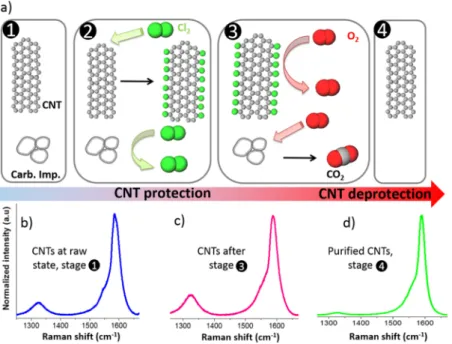
We present here experimental results that evidence a high selectivity in the elimination of carbonaceous impurities with respect to CNTs occurring in particular working conditions. Moreover, in contrast with the few available reported non-damaging methods, our approach allows to prepare purified CNTs while limiting the number of chemical treatments.43−45 Our entirely gas-phase treatment consists of a concomitant thermal activation of a protection/combustion effect of the carbon species before the spontaneous elimination of the formed metallic chlorides in a one-pot treatment. The favored oxidation of carbonaceous impurities is demonstrated by applying this treatment to both single-walled CNTs (SWCNTs) and DWCNTs. The results show that the combination of chlorine and oxygen at temperatures as low as 350−500 °C can be a powerful asset for an effective carbon impurity elimination with a much higher carbon yield than previously reported 81 wt % instead of 5 wt %.42These results have been achieved thanks to a strong protecting effect of CNTs against combustion occurring in a quite low-temper-ature range (350−500 °C) when oxygen is introduced in chlorine while carbonaceous impurities remain susceptible to be vaporized. The proposed reaction mechanism, unprece-dented in the literature, which allows to explain thisfinding, is based on the identified tunable reactivity between oxygen and chlorine toward carbon species, that is, CNTs and carbon impurities. The method we propose here hence fulfills all of the requirements to purify large volumes of CNTs with high sample yields, which is of great interest for their practical applications.
2. MATERIALS AND METHODS
2.1. CNT Purification. The DWCNT sample was synthesized by catalytic chemical vapor deposition under optimized operating conditions;46the raw DWCNT sample is referred to as rD. The raw HiPco SWCNT samples used for this work were supplied by NanoIntegris Inc. For the purification of the HiPco sample, because of the numerous conditions tested, we had to use several raw batches of
SWCNTs. Each one has been distinguished: rS1-2 is the starting raw SWCNT sample, which has been purified to prepare S1 and S2; rS3-5 corresponds to the raw SWCNTs used to obtain S3, S4, and S5; and rS6 for S6. The experimental conditions used for the purification of both SWCNTs and DWCNTs are given in the Supporting Information, Table S1. Moreover, the treatment of a DWCNT sample was intentionally stopped after the O2
dwell under Cl2at 500°C; this sample is referred to as mD. For the purification treatment (Figure 1), the CNT powder (∼150 mg) was placed in a silica boat (length 10 cm) in a
tubular oven (diameter 2 cm), which was first flushed by nitrogen (nitrogen being also the carrier gas for the process) to carefully remove air; purified chlorine at around 200 mL/min was incorporated into the set-up while the temperature was increased (10 °C/min). When the temperature reached the chosen value, TO2(TO2variation range: 250−950 °C), O2with a flow rate of 2−4 mL/min was injected for the desired duration (t1−t2 in the 20−60 min range). After the Cl2/O2
treatment stage, the sample was heated at TCl2for 1 h under
chlorine alone before natural cooling (see alsoTable S1). With the used conditions regarding the O2 flow rate and duration of its injection, the used O2volume is around 200 mL
(9× 10⁻³mol). The amount of carbon for the experiments is at most 8× 10⁻³mol. That means that for every experiment carried out, the amount of oxygen content used is sufficient enough to burn all the unwanted carbon-based species.
2.2. Characterization Techniques. Transmission elec-tron microscopy (TEM) observations were performed using a JEM-ARM 200F apparatus at an accelerating voltage of 80 kV. At least 30−40 images taken at different places were analyzed for each sample in order to guarantee a representative description of the samples. Thermogravimetric analysis (TGA) was performed with a Setaram Setsys evolution 1750 by using dry air as the carrier gas and a temperature ramp of 5 °C/min from room temperature to 900 °C. The metal oxide content evaluated by TGA was directly used to calculate the yield of removal of metallic impurity (Ym) after purification; that means that the oxygen part corresponding to the respective stoichiometric amount in the oxidized form of each metal present in the (raw or purified) CNT samples is included in Ym.
Micro-Raman spectroscopy was carried out with a LabRAM HR 800 micro-Raman spectrometer with two incident wavelengths: 632.8 and 514.5 nm. The incident laser beam, focused on the sample with an×50 objective, was reduced with an opticfilter to avoid any damage due to overheating during
Figure 1. Schematic of the applied one-pot purification method
displaying the nature of the gas used in each step, and the temperature sequence (dwells and ramps).
the spectrum recording. The recorded number of spectra (at least 3) depended on the observed data dispersion. After subtraction of a baseline, the ID/IG intensity ratio was determined by dividing the height of the D band by that of the G band. As only one representative spectrum is shown for each sample, the D/G ratio was close to the average of ID/IGof
the sample. The given ID/IG evolutions correspond to the evolution of the average value of the ID/IGratios obtained for
each spectrum for the sample, after the applied chemical treatment. For Auger electron spectroscopy (AES), the CNT powder isfixed with a copper scotch on a molybdenum sample holder. A primary electron energy of 2500 eV is focused on the sample, and a cylindrical detector with a resolution of 1 eV is used for data collection.
X-ray photoelectron spectroscopy (XPS) spectra were collected on a Kratos Axis Ultra (Kratos Analytical, UK) spectrometer equipped with a monochromatic Al Kα source (1486.6 eV). All spectra were recorded at a 90° takeoff angle, with the analyzed area being about 0.7 × 0.3 mm. Survey spectra were acquired with 1.0 eV step and 160 eV analyzer pass energy and the high-resolution regions with 0.1 eV step and 20 eV pass energy (instrumental resolution better than 0.5 eV). Curvefitting was performed using a Gaussian/Lorentzian (70/30) peak shape after Shirley’s background subtraction and using the X-vision 2.2.11 software.
3. RESULTS AND DISCUSSION
3.1. Purification Approach, Carbonaceous Impurity Removal, and CNT Quality. From the synthesis method, catalyst residues remain in the CNT samples, including DWCNTs and SWCNTs. DWCNTs contain cobalt- and molybdenum-based impurities. The latter represent about 10% of the sample weight. The as-produced HiPco SWCNT sample contains iron-based impurities at a non-negligible amount, reaching a third or more of the sample weight. The used DWCNTs have an internal and external average diameter of 1.35 and 2.05 nm, respectively, with a length between 1 and 10 μm. The diameter of the SWCNTs varies from 0.7 to 2 nm, and their length is similar to that of the DWCNTs. Non-nanotube carbon species are also present in both CNT samples, inherent to the chemical vapor deposition (CVD) synthesis. The close reactivity between these carbonaceous impurities and the CNTs is clearly put into evidence from their resistance against oxidation by means of TGA. The combustion of CNT samples commonly appears as one single weight loss, meaning that CNTs and non-nanotube carbon species burn off in the same temperature range, as is the case also for the DWCNTs and SWCNTs used here (cf.Figure 2). The as-produced DWCNT and SWCNT powders were submitted to our one-pot thermal treatment under chlorine (until Tmax), in which oxygen is introduced at a chosen temperature, TO2 (TO2 being ≤T
max), the carrier gas being
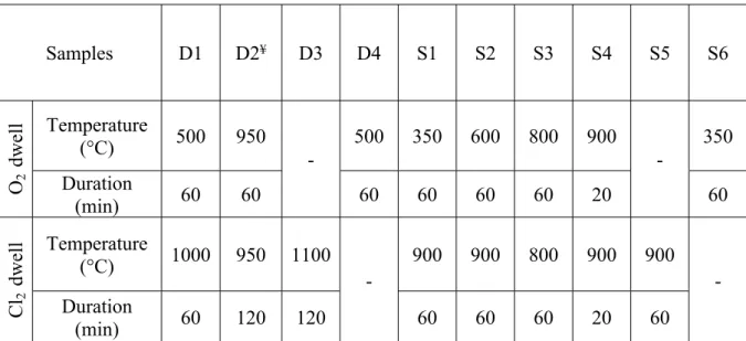
nitrogen, N2 (Figure 1 and Table 1). With the aim of
investigating the mechanisms involved in the Cl2/O2-based treatment, we have performed experiments with different approaches: (i) O2 was introduced in the reactor at a temperature lower than that used for the final dwell in chlorine (TO2< Tmax) (D1, S1, and S2); (ii) O
2was introduced
during the Cl2 dwell, TO2 = T
max (D2, S3, and S4); (iii)
treatments under Cl2only (D3 and S5) or O2only (D4 and
S6) were also conducted (Table 1andSupporting Information, Table S1). Among all of the performed treatments, for the sake
of clarity, we present those showing significant differences in metallic removal and/or carbon impurity elimination, con-sistency and reproducibility having been carefully tested.
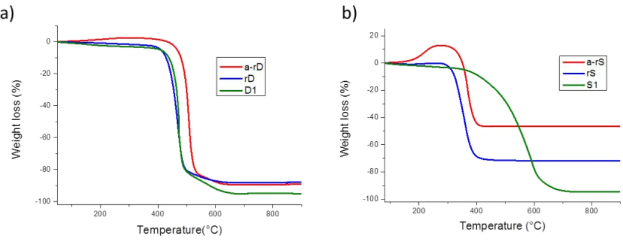
The typical behavior from TGA of the raw and treated CNT samples after treatment with Cl2alone and with a mixture Cl2/ O2 is shown in Figure 2. For the raw DWCNT sample, the
shape of the TGA curves and the observed combustion temperatures are quite similar (around 500 °C) before and after purification (Figure 2a). Raw SWCNTs burn off around 350 °C, and the combustion temperature is upshifted to around 550°C after purification (Figure 2b). The pronounced upshift (∼+200 °C) of the combustion temperature for SWCNTs may be due to the greater metal content in this sample compared to that in DWCNT; the upshift of the burn-off temperature of CNTs is indeed commonly observed after the elimination of the metallic impurities47 (Supporting Information, Figure S1).
Figure 3 shows TEM images of the used DWCNT and SWCNT samples before (Figure 3, rD and rS) and after different treatment conditions. Metallic and carbon impurities can be easily noticed in both SWCNT and DWCNT samples on the TEM images of the starting raw samples. As normally observed, these impurities widely cover the CNT interlacing. After heating the powdered CNT sample under chlorine, carbon impurities were still present and could be clearly imaged (Figure 3, D3 and S5). These non-nanotube species
Figure 2.TGA curves (in dry air, temperature ramp 5°C/min) for
the raw and selected CNTs treated with Cl2 and Cl2/O2 (a): raw
DWCNT rD (blue); Cl2-purified DWCNT D3 (red); Cl2/O2-purified
DWCNT D1 (green) and for SWCNTs (b): raw SWCNT (blue)
rS1-2; Cl2-purified SWCNT S5 (red); Cl2/O2-purified SWCNT S1
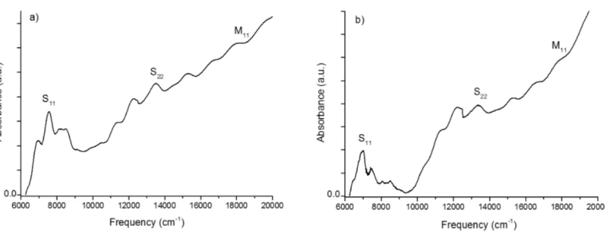
are present in various shapes, more or less spherical or crooked particles, with a size in the 5−10 nm range or higher. On the nanometer scale, their structure is quite well ordered with graphitic multi-layer walls observable at high magnification (not shown). Quantifying the carbonaceous impurities within a CNT sample is complex.48−51Even if they remain very rough, their content can be estimated from TEM,28about 10−30% in these samples. As expected and already reported by applying chlorine alone,40,41carbon impurities were not eliminated from the CNT samples (D3 and S5). However, they were completely destroyed as oxygen was added to chlorine (Figure 3, D1 and S1). In the Cl2/O2-treated samples (D1, D2, S1, S2, S3, and S4), CNTs appear very clean, without any other impurity visible on most of the TEM images (Table 1). From time to time, either metallic or carbon impurities could still be observed, but the efficiency of their removal is really obvious. In the presence of chlorine, the carbon impurities could be selectively eliminated from the CNT samples when O2 was introduced at 500 °C or higher and at 350 °C or higher for DWCNTs and SWCNTs, respectively. Absorbance spectros-copy, performed on S1 (corresponding to the SWCNTs
purified by using the optimized conditions), has shown that carbon impurity content was significantly reduced in these purified SWCNTs compared to the raw SWCNTs (cf.
Supporting Information, Figure S2). If O2 is introduced at lower temperature, the amount of carbon impurities with respect to CNTs is similar to what is observed in the respective raw sample. When only oxygen was used (D4 and S6), carbon impurities were not eliminated from the samples (not shown) and combustion of both CNTs and carbon impurities occurred simultaneously, as further discussed from TGA.
Raman spectroscopy is a powerful technique to probe any modification (improvement or damaging) of the CNT structure after a chemical treatment.52In a Raman spectrum, the G band (around 1590 cm−1) is characteristic of the sp2 network formed by the double-bonded carbon atoms and the D band (around 1330 cm−1) is related to“disorder” or defects when the hybridization of carbon atoms turns to sp3through damaging or functionalization. The evolution of the ID/IG intensity ratio is hence a signature of the structural quality modification of CNTs.Figure 4gives the variation of the ID/IG intensity ratio for the studied samples, including Cl2-, O2-, and
Cl2/O2-purified CNTs for both DWCNT and SWCNT.
For our treatment conditions, except for S2 with the red incident wavelength (λ = 632.8 nm), for which the temperature (600 °C) for oxygen introduction can be prejudicial to some part of CNTs, ID/IG was decreased for all the treated samples, meaning that the CNTs were not damaged by any of the applied treatments (Figure 4). The observed decrease in the D band might be due to various Table 1. Temperature at Which O2Is Introduced in the Purification Reactor, Temperature of Cl2Dwell (Tmax), Occurrence of
Carbon Impurity Removal, Resulting Oxidized Metallic Impurity ContentMpin wt % and Their Contentnmin at. %, Metal
Removal YieldYm, and Carbon Consumption after Purification Cca
sample O2introduction temperature (TO2)/°C Cl2dwell temperature (T
max)/°C carbon impurity removal M
p(Mr)/wt % nm/at. % Ym/% Cc/% rD 10.2 1.9 D1 500 1000 y 4.8 0.9 53 19 D2¥ 950 950 y 0.01 0.002 99.9 95 D3 1100 n 5.5 1.0 46 21 D4 500 n 72.8 13.5 98 rS1-2 28.0 7.7 S1 350 900 y 5.4 1.2 81 11 S2 600 900 y 4.8 1.1 83 47 rS3-5 44.5 14.7 S3 800 800 y 5.0 1.1 88.8 76 S4 900 900 y 3.6 0.8 91.9 91 S5 900 n 5.2 1.2 88.3 3 rS6 33.0 9.6 S6 350 n N.A. aY
mand Ccare defined in the text.¥From an earlier work.42
Figure 3. Typical TEM bright-field micrographs of the raw and
treated DWCNT and SWCNT samples: raw DWCNT (rD), Cl2
-purified DWCNT (D3), Cl2/O2-purified DWCNT (D1), raw
SWCNT (rS1-2), Cl2-purified SWCNT (S5), Cl2/O2-purified
SWCNT (S1).
Figure 4.Variation of ID/IG(%) of each treated sample compared to
effects, which can be also combined: (i) curing of CNT defects due to the high temperature used, and (ii) elimination of the most defective CNTs, (iii) removal of amorphous carbon layers deposited on CNTs.53,54
3.2. Impurity Removal Yield, Sample Yield, and Overall Efficiency of the Purification Method. TGA in air is commonly used to determine oxidized mineral impurity content in CNT samples. With increasing temperature, complete combustion of the carbon species occurs, and the remaining weight corresponds to non-carbon impurities: that is, oxidized metallic impurities. As usually encountered, the oxidized metallic impurities, Mr, are about 10 wt % (∼2 at. %) and 30−45 wt % (∼7−15 at. %) for the used raw DWCNT and SWCNT samples, respectively (Table 1). The atomic content of metal-based impurities, nm, was roughly estimated
by dividing the metal oxide weight (from TGA) by the molar mass of the corresponding catalyst(s).
Whatever the CNT purification conditions, in the presence of chlorine, the content of the metal residues (nm) falls down to values close to 1 at. % for the two types of samples (Table 1). Removal of metal impurities certainly occurs in the high-temperature range when either Cl2or Cl2/O2is used. At these
temperatures, metal chlorides are easily formed and their sublimation is favored,41leading to their elimination from the CNT samples.
The metal removal yield, Ym, is defined as = − Y M M M m r p r ,
where Mr and Mpcorrespond to the mineral residue content from TGA, that is, the oxidized metallic impurities of the raw and the purified CNT, respectively. Ymis relatively good (80−
90%), especially for SWCNTs because the raw SWCNT sample contains a large amount of catalyst impurities. That part of remaining metal residues is much more difficult to remove from the samples without destroying the majority of CNTs. It certainly corresponds to the metal nanoparticles already described to be highly protected in the CNT inner channels, their encapsulation occurring during CNT growth by CVD.5,55−57 For both DWCNT and SWCNT samples, the
carbon impurities could be efficiently eliminated when Cl2/O2 was used instead of Cl2alone (Figure 2and Table 1).
The second relevant parameter to assess a CNT purification process is the carbon consumption (Cc) because it eventually
allows to appreciate the CNTs lost through the treatment. Cc
corresponds to the carbon loss through purification:
= − − − − C M M Y M c 100 (100 ) 100 r p s r , where = Y m m s p
r is the overall sample
yield determined from the ratio between the weight of the purified sample mpover the mass of the raw one mr. We point out that Cc includes the consumption of both CNTs and carbon impurities. As expected, increasing TO2, which allows a
better catalyst removal, also induces high carbon consumption (>50%) (D2, S4, and S5). Importantly, this consumption is well below 50% for D1 and S1, samples in which metallic and carbon impurities have been removed with good yields for both of them.
In the literature, it is problematic to retrieve the overall sample loss or carbon impurity loss because of the complexity of the applied treatments and the multi-step nature of the methods involved. Regarding DWCNTs, Flahaut et al. have reported an effective elimination of disordered carbon species by air53 with a sample yield lower than 20%.31 Selective elimination of carbon impurities from SWCNT samples is found in a few studies. The work by Dementev et al. reported the selective removal of carbon impurities from (arc discharge-produced) SWCNTs by dynamic air oxidation, but metal impurities were not removed.58 Rosario-Castro et al. used a standard multi-step purification method for purifying HiPco SWCNTs, including a nitric acid treatment followed by wet air oxidation and Soxhlet extraction in HCl, andfinally, the sample was annealed at 425°C.59Iron content was reduced by 89%, and carbon loss subsequent to the applied treatments was not determined. Wang et al. applied a wet combined treatment using H2O2and HCl. They could decrease the iron content in HiPco SWCNTs by 86% while keeping a carbon yield of 75%, but “little damage” of the CNT sidewalls was reported.44
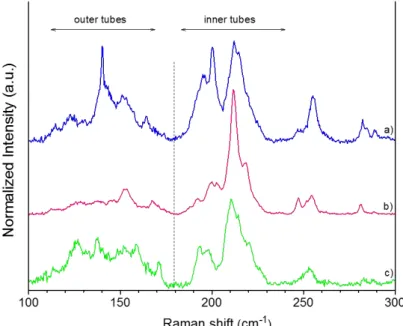
Figure 5.(a) Proposed mechanism for the selective removal of carbon impurities. (1) t = ti; (2) t≤ t1; (3) t1≤ t ≤ t2; (4) t = tf; txis the time
sequence as defined inFigure 1. Also, typical Raman spectroscopy spectrum of DWCNTs in the raw state (b), DWCNTs collected just after the
Among the purification procedures involved in halogen-based compounds, after the oxidation of iron impurities by oxygen, Xu et al. used a mixture offluorinated compounds (SF6 and
C2H2F4) to form metal fluorides eliminated by subsequent
Soxhlet extraction (multi-step method).60 The authors reported a SWCNT yield of 68% with“little sidewall damage”. Zimmerman et al. have developed a chlorine-based method consisting of bubbling Cl2 in HCl containing SWCNTs, and they lost 96 wt % of the starting HiPco SWCNTs sample.38To the best of our knowledge, purification showing a selective elimination of carbon impurities, with low carbon consumption (<50%) and without any CNT damage, has not been reported yet. Remarkably, our results show that the method we propose is able to successfully combine metal elimination and selective attack of carbon impurities among carbon species in a one-pot treatment. The structural quality of the purified CNTs is preserved and even improved without an excessive con-sumption of the nanotubes.
3.3. Proposed Mechanism. We propose a mechanism explaining the combustion selectivity toward the carbonaceous impurities based on the known specific reactivity between halogens and carbon nanomaterials, including CNTs. This mechanism also originates from a deep analysis of the behavior of carbon nanomaterials in an oxidative medium.
The mechanism proposed in Figure 5a is based on several consistent aspects.Figure 5a(1) schematizes the CNTs and the carbonaceous impurities. In this work, from combustion selectivity of the carbon impurities observed with and without chlorine (see, for instance, D1 and D3), it is obvious that chlorine plays the major role in preventing CNT from combustion by oxygen. The reactivity of CNTs with halogens or halogenated compounds has shown remarkable effects in carbon chemistry.61 For example, regarding fluorine, the easiness62,63and reversibility64,65of thefluorination of CNTs account for its extensive interest especially because fluo-rocarbons could be used in a lot of applications. Grafting of chlorine to large sp2-based carbon materials or carbon impurities has been shown to be less favorable than the formation of covalent C−Cl bonds on smaller and high-quality CNTs.66,67 In our samples, both DWCNTs and SWCNTs have a lower curvature radius (<3 nm) compared to that within the non-nanotube species (>5 nm), as observed by TEM. CNTs with a smaller diameter are thus expected to have a better affinity with chlorine (Figure 5a(2)). Compared to the raw CNTs (Figure 5b), Raman spectroscopy performed on the CNT sample for which the treatment was stopped just after the Cl2/O2dwell (mD), on purpose, shows an increase in the D/G ratio compared to the raw CNTs (Figure 5c). The intensity of the D band is decreased at the end of the Cl2/O2-process, as shown inFigure 5d and in agreement withFigure 4. We have
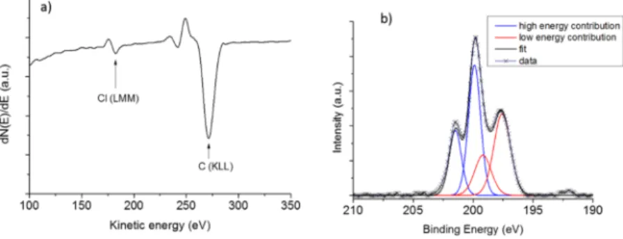
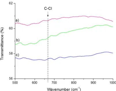
not observed any G-band shift probably because of the too small amount of chlorine-containing functional groups present on the CNT walls. Such G-band shift because of doping effect by halogen was reported to be weakly pronounced or not visible afterfluorine grafting.63,68However, the observed D/G ratio for mD may be attributed to covalent functionalization of the CNT walls by chlorine (cf. also Supporting Information, Figure S3). This hypothesis is also supported by the AES of this CNT sample for which chlorine could be well detected69 [Figure 6a and Fourier transform infrared (FTIR) results,
Supporting Information, Figure S4]. XPS analysis also revealed the presence of chlorine species at the surface of mD (Figure 6b). Two components (each consisting of the 3/2 and 1/2 level with a spin−orbit splitting of 1.6 eV) were required to obtain a satisfactoryfit of the Cl 2p core-level spectrum. The low-energy contribution with the 2p3/2component at ca. 197.5
eV corresponds to more electronegative chlorine atoms probably coming from metal. The high-energy contribution with the 2p3/2 component at ca. 199.9 eV is attributed to
chlorine bonded to carbon70 in agreement with Raman spectroscopy. From XPS, chlorine atomic content was decreased by a factor of almost 2 between mD and D1, being as low as around 0.83 at. % in D1 (Supporting Information, Figure S5).
Even if chlorine is only sparsely attached to the CNTs, its known power as aflame retardant leads to a favored carbon impurity combustion when oxygen is introduced in the reactor. This protective shield against combustion, which has been already suggested without any evidence,38,42 leads to the combustion of carbonaceous impurities by O2at TO2whereas
the CNTs are protected by Cl2(Figure 5a(3)). This protection induces a substantial improvement of removal selectivity between carbonaceous impurities and CNTs close to the combustion temperature (S1, D1). This beneficial effect disappears when TO2is increased, because carbon combustion becomes highly favorable and very fast (S2, S3, and S4). The well-known lability of the C−Cl bond certainly favors the detachment of chlorine from the CNTs by heating (Figure 5a(4),d). On the basis of the proposed mechanism, our method is versatile because purification occurs with optimum efficiency as oxygen is introduced at the combustion temperature of the samples for both DWCNT and SWCNT.
4. CONCLUSIONS
This work proposes a solution to the long-standing issue of carbon impurities removal while avoiding excessive attack and consumption of CNTs. The challenge comes from the widely known too close chemical reactivity of carbon impurities and CNTs. This is an importantfinding because CNT purification
cannot be avoided for a lot of applications and the existing purification methods are time and sample consuming. Our one-pot treatment consists of heating the sample under chlorine up to Tmax(around 1000°C) and introducing oxygen at a given temperature, TO2≤ Tmax. The best treatment is then
obtained when TO2 corresponds to the combustion
temper-ature range of the CNT sample, as determined by TGA. We have shown that chlorine plays an essential role by combining the removal of metallic impurities and protection of the CNTs from combustion. Moreover, the efficiency of the proposed method has been demonstrated to be due to a substantial increase in the combustion selectivity of the carbonaceous impurities with respect to CNTs. The proposed mechanism appears then to be a powerful tool because it could be easily adapted to other source of carbon nanostructures with other kind of metal impurities (Ni, Al, ...) also. Moreover, the present approach has the enormous advantage to produce, in a one-pot treatment, large volumes of purified CNTs. The developed treatment process hence has a high scale-up potential, and it could open new opportunities for CNT applications.
■
ASSOCIATED CONTENT*
S Supporting InformationThe Supporting Information is available free of charge on the
ACS Publications websiteat DOI:10.1021/acs.jpcc.8b12554. Experimental conditions for the performed treatments for both DWCNTs and SWCNTs, stability against combustion from TGA under dry air after applying an annealing program under helium, carbon impurity in SWCNT samples investigated by UV−NIR absorbance spectroscopy, chlorine grafting to CNT walls evidenced by RBM analysis from Raman spectroscopy and with FTIR, and XPS wide scans for rD, D1, and mD (PDF)
■
AUTHOR INFORMATIONCorresponding Author
*E-mail:Brigitte.Vigolo@univ-lorraine.fr. Phone: +33 372 742 533.
ORCID
Brigitte Vigolo:0000-0002-1463-0121 Notes
The authors declare no competingfinancial interest.
■
ACKNOWLEDGMENTSThe authors would like to thank L. Aranda and P. Franchetti for their help for TGA and Raman spectroscopy experiment, respectively. They also thank Prof. Dr. M. Dubois for the fruitful discussions aboutfluorine chemistry. P. Lonchambon is acknowledged for help with sample preparation. The authors thank the University of Lorraine for its financial support, especially for N.B.’s Doctoral Fellowship. Auger experiments were performed using equipment from the TUBEDavm funded by FEDER (EU) at IJL, ANR, the Region Lorraine and Grand Nancy. We acknowledge L. Pasquier and Prof. Dr. S. Andrieu from Institut Jean Lamour for performing the Auger experiments and analysis. We would like to thank the platform “Spectroscopies et Microscopies des Interfaces” (Laboratory of Physical Chemistry and Microbiology for Materials and the Environment, LCPME, Nancy, France) and A. Renard, Dr. M. Mallet (LCPME) and Dr. M. Dossot for XPS and absorbance
analyses. This work was partly supported by the PRC CNRS/ RFBR grant no. 1023.
■
REFERENCES(1) Ajayan, P. M.; Zhou, O. Z. Applications of Carbon Nanotubes. In Carbon Nanotubes: Synthesis, Structure, Properties, and Applications; Dresselhaus, M. S., Dresselhaus, G., Avouris, P. H., Eds.; Springer-Verlag Berlin: Berlin, 2001; Vol. 80, pp 391−425.
(2) Grobert, N. Carbon Nanotubes - Becoming Clean. Mater. Today 2007, 10, 28−35.
(3) Zhang, Q.; Huang, J.-Q.; Zhao, M.-Q.; Qian, W.-Z.; Wei, F. Carbon Nanotube Mass Production: Principles and Processes. ChemSusChem 2011, 4, 864−889.
(4) Jia, X.; Wei, F. Advances in Production and Applications of Carbon Nanotubes. Top. Curr. Chem. 2017, 375, 18.
(5) Cui, C.; Qian, W.; Zheng, C.; Liu, Y.; Yun, S.; Yu, Y.; Nie, J.; Wei, F. Formation Mechanism of Carbon Encapsulated Fe Nano-particles in the Growth of Single-/Double-Walled Carbon Nanotubes. Chem. Eng. J. 2013, 223, 617−622.
(6) Yadav, M. D.; Dasgupta, K.; Patwardhan, A. W.; Kaushal, A.; Joshi, J. B. Kinetic study of single-walled carbon nanotube synthesis by thermocatalytic decomposition of methane using floating catalyst chemical vapour deposition. Chem. Eng. Sci. 2019, 196, 91−103.
(7) Pumera, M. Voltammetry of Carbon Nanotubes and Graphenes: Excitement, Disappointment, and Reality. Chem. Rec. 2012, 12, 201− 213.
(8) Pan, H.; Li, J.; Feng, Y. P. Carbon Nanotubes for Supercapacitor. Nanoscale Res. Lett. 2010, 5, 654.
(9) Vejpravova, J.; Pacakova, B.; Kalbac, M. Magnetic Impurities in Single-Walled Carbon Nanotubes and Graphene: A Review. Analyst 2016, 141, 2639−2656.
(10) Matsumoto, N.; Chen, G.; Yumura, M.; Futaba, D. N.; Hata, K. Quantitative Assessment of the Effect of Purity on the Properties of Single Wall Carbon Nanotubes. Nanoscale 2015, 7, 5126−5133.
(11) Kruusma, J.; Mould, N.; Jurkschat, K.; Crossley, A.; Banks, C. E. Single Walled Carbon Nanotubes Contain Residual Iron Oxide Impurities Which Can Dominate Their Electrochemical Activity. Electrochem. Commun. 2007, 9, 2330−2333.
(12) Šljukić, B.; Banks, C. E.; Compton, R. G. Iron Oxide Particles Are the Active Sites for Hydrogen Peroxide Sensing at Multiwalled Carbon Nanotube Modified Electrodes. Nano Lett. 2006, 6, 1556− 1558.
(13) Wang, L.; Ambrosi, A.; Pumera, M. Carbonaceous Impurities in Carbon Nanotubes Are Responsible for Accelerated Electrochemistry
of Cytochrome c. Anal. Chem. 2013, 85, 6195−6197.
(14) Stuart, E. J. E.; Pumera, M. Nanographite Impurities within Carbon Nanotubes Are Responsible for Their Stable and Sensitive Response Toward Electrochemical Oxidation of Phenols. J. Phys. Chem. C 2011, 115, 5530−5534.
(15) Wang, L.; Ambrosi, A.; Pumera, M. Carbonaceous Impurities in Carbon Nanotubes Are Responsible for Accelerated Electrochemistry of Acetaminophen. Electrochem. Commun. 2013, 26, 71−73.
(16) Pumera, M.; Ambrosi, A.; Chng, E. L. K. Impurities in Graphenes and Carbon Nanotubes and Their Influence on the Redox Properties. Chem. Sci. 2012, 3, 3347−3355.
(17) Hou, P.-X.; Liu, C.; Cheng, H.-M. Purification of Carbon
Nanotubes. Carbon 2008, 46, 2003−2025.
(18) Makama, A. B.; Salmiaton, A.; Abdullah, N.; Choong, T. S. Y.; Saion, E. B. Recent Developments in Purification of Single Wall Carbon Nanotubes. Sep. Sci. Technol. 2014, 49, 2797−2812.
(19) Andrews, R.; Jacques, D.; Qian, D.; Dickey, E. C. Purification and Structural Annealing of Multiwalled Carbon Nanotubes at Graphitization Temperatures. Carbon 2001, 39, 1681−1687.
(20) Zhang, H.; Sun, C. H.; Li, F.; Li, H. X.; Cheng, H. M. Purification of Multiwalled Carbon Nanotubes by Annealing and Extraction Based on the Difference in van Der Waals Potential. J. Phys. Chem. B 2006, 110, 9477−9481.
(21) Huang, W.; Wang, Y.; Luo, G. H.; Wei, F. 99.9% Purity Multi-Walled Carbon Nanotubes by Vacuum High-Temperature Annealing.
Carbon 2003, 41, 2585−2590.
(22) Cho, H. G.; Kim, S. W.; Lim, H. J.; Yun, C. H.; Lee, H. S.; Park, C. R. A Simple and Highly Effective Process for the Purification of Single-Walled Carbon Nanotubes Synthesized with Arc-Discharge. Carbon 2009, 47, 3544−3549.
(23) Mercier, G.; Gleize, J.; Ghanbaja, J.; Marêché, J.-F.; Vigolo, B. Soft Oxidation of Single-Walled Carbon Nanotube Samples. J. Phys. Chem. C 2013, 117, 8522−8529.
(24) Vigolo, B.; Hérold, C.; Marêché, J.-F.; Ghanbaja, J.; Gulas, M.; Normand, F. L.; Almairac, R.; Alvarez, L.; Bantignies, J.-L. A Comprehensive Scenario for Commonly Used Purification Proce-dures of Arc-Discharge as-Produced Single-Walled Carbon Nano-tubes. Carbon 2010, 48, 949−963.
(25) Salzmann, C. G.; Llewellyn, S. A.; Tobias, G.; Ward, M. A. H.; Huh, Y.; Green, M. L. H. The Role of Carboxylated Carbonaceous Fragments in the Functionalization and Spectroscopy of a Single-Walled Carbon-Nanotube Material. Adv. Mater. 2007, 19, 883.
(26) An, Z.; Furmanchuk, A. o.; Ramachandramoorthy, R.; Filleter, T.; Roenbeck, M. R.; Espinosa, H. D.; Schatz, G. C.; Nguyen, S. T. Inherent Carbonaceous Impurities on Arc-Discharge Multiwalled Carbon Nanotubes and Their Implications for Nanoscale Interfaces.
Carbon 2014, 80, 1−11.
(27) Ismail, A. F.; Goh, P. S.; Tee, J. C.; Sanip, S. M.; Aziz, M. A Review of Purification Techniques for Carbon Nanotubes. NANO
2008, 03, 127−143.
(28) Park, T.-J.; Banerjee, S.; Hemraj-Benny, T.; Wong, S. S. Purification Strategies and Purity Visualization Techniques for Single-Walled Carbon Nanotubes. J. Mater. Chem. 2006, 16, 141−154.
(29) Li, C.; Wang, D.; Liang, T.; Wang, X.; Wu, J.; Hu, X.; Liang, J. Oxidation of Multiwalled Carbon Nanotubes by Air: Benefits for
Electric Double Layer Capacitors. Powder Technol. 2004, 142, 175−
179.
(30) Shaffer, M. S. P.; Fan, X.; Windle, A. H. Dispersion and Packing of Carbon Nanotubes. Carbon 1998, 36, 1603−1612.
(31) Bortolamiol, T.; Lukanov, P.; Galibert, A.-M.; Soula, B.; Lonchambon, P.; Datas, L.; Flahaut, E. Double-Walled Carbon Nanotubes: Quantitative Purification Assessment, Balance between Purification and Degradation and Solution Filling as an Evidence of
Opening. Carbon 2014, 78, 79−90.
(32) Ando, Y.; Zhao, X.; Shimoyama, H. Structure Analysis of Purified Multiwalled Carbon Nanotubes. Carbon 2001, 39, 569−574. (33) Vivekchand, S. R. C.; Govindaraj, A.; Seikh, M. M.; Rao, C. N. R. New Method of Purification of Carbon Nanotubes Based on Hydrogen Treatment. J. Phys. Chem. B 2004, 108, 6935−6937.
(34) Wang, Y.; Gao, L.; Sun, J.; Liu, Y.; Zheng, S.; Kajiura, H.; Li, Y.; Noda, K. An Integrated Route for Purification, Cutting and Dispersion of Single-Walled Carbon Nanotubes. Chem. Phys. Lett. 2006, 432, 205−208.
(35) Smith, M. R.; Hedges, S. W.; LaCount, R.; Kern, D.; Shah, N.; Huffman, G. P.; Bockrath, B. Selective Oxidation of Single-Walled Carbon Nanotubes Using Carbon Dioxide. Carbon 2003, 41, 1221− 1230.
(36) Delpeux, S.; Szostak, K.; Frackowiak, E.; Béguin, F. An efficient two-step process for producing opened multi-walled carbon
nano-tubes of high purity. Chem. Phys. Lett. 2005, 404, 374−378.
(37) Żarska, S.; Kulawik, D.; Drabowicz, J.; Ciesielski, W. A Review of Procedures of Purification and Chemical Modification of Carbon Nanotubes with Bromine. Fullerenes, Nanotubes, Carbon Nanostruct. 2017, 25, 563−569.
(38) Zimmerman, J. L.; Bradley, R. K.; Huffman, C. B.; Hauge, R. H.; Margrave, J. L. Gas-Phase Purification of Single-Wall Carbon
Nanotubes. Chem. Mater. 2000, 12, 1361−1366.
(39) Barkauskas, J.; Stankevičienė, I.; Selskis, A. A Novel Purification Method of Carbon Nanotubes by High-Temperature Treatment with Tetrachloromethane. Sep. Purif. Technol. 2010, 71, 331−336.
(40) Chng, E. L. K.; Poh, H. L.; Sofer, Z.; Pumera, M. Purification of Carbon Nanotubes by High Temperature Chlorine Gas Treatment. Phys. Chem. Chem. Phys. 2013, 15, 5615−5619.
(41) Mercier, G.; Hérold, C.; Marêché, J.-F.; Cahen, S.; Gleize, J.; Ghanbaja, J.; Lamura, G.; Bellouard, C.; Vigolo, B. Selective Removal of Metal Impurities from Single Walled Carbon Nanotube Samples.
New J. Chem. 2013, 37, 790−795.
(42) Desforges, A.; Bridi, A. V.; Kadok, J.; Flahaut, E.; Le Normand, F.; Gleize, J.; Bellouard, C.; Ghanbaja, J.; Vigolo, B. Dramatic Enhancement of Double-Walled Carbon Nanotube Quality through a One-Pot Tunable Purification Method. Carbon 2016, 110, 292−303. (43) Ma, J.; Wang, J. N. Purification of Single-Walled Carbon Nanotubes by a Highly Efficient and Nondestructive Approach. Chem. Mater. 2008, 20, 2895−2902.
(44) Wang, Y.; Shan, H.; Hauge, R. H.; Pasquali, M.; Smalley, R. E. A Highly Selective, One-Pot Purification Method for Single-Walled Carbon Nanotubes. J. Phys. Chem. B 2007, 111, 1249−1252.
(45) Ballesteros, B.; Tobias, G.; Shao, L.; Pellicer, E.; Nogués, J.; Mendoza, E.; Green, M. L. H. Steam Purification for the Removal of Graphitic Shells Coating Catalytic Particles and the Shortening of
Single-Walled Carbon Nanotubes. Small 2008, 4, 1501−1506.
(46) Flahaut, E.; Bacsa, R.; Peigney, A.; Laurent, C. Gram-Scale CCVD Synthesis of Double-Walled Carbon Nanotubes. Chem.
Commun. 2003, 12, 1442−1443.
(47) Chiang, I. W.; Brinson, B. E.; Smalley, R. E.; Margrave, J. L.; Hauge, R. H. Purification and Characterization of Single-Wall Carbon
Nanotubes. J. Phys. Chem. B 2001, 105, 1157−1161.
(48) Sen, R.; Rickard, S. M.; Itkis, M. E.; Haddon, R. C. Controlled Purification of Single-Walled Carbon Nanotube Films by Use of Selective Oxidation and Near-IR Spectroscopy. Chem. Mater. 2003, 15, 4273−4279.
(49) Dillon, A. C.; Yudasaka, M.; Dresselhaus, M. S. Employing Raman Spectroscopy to Qualitatively Evaluate the Purity of Carbon Single-Wall Nanotube Materials. J. Nanosci. Nanotechnol. 2004, 4,
691−703.
(50) Itkis, M. E.; Perea, D. E.; Jung, R.; Niyogi, S.; Haddon, R. C. Comparison of Analytical Techniques for Purity Evaluation of
Single-Walled Carbon Nanotubes. J. Am. Chem. Soc. 2005, 127, 3439−3448.
(51) Arepalli, S.; Nikolaev, P.; Gorelik, O.; Hadjiev, V. G.; Holmes, W.; Files, B.; Yowell, L.; Yowell, L. Protocol for the Characterization of Single-Wall Carbon Nanotube Material Quality. Carbon 2004, 42, 1783−1791.
(52) Dillon, A. C.; Parilla, P. A.; Alleman, J. L.; Gennett, T.; Jones, K. M.; Heben, M. J. Systematic Inclusion of Defects in Pure Carbon Single-Wall Nanotubes and Their Effect on the Raman D-Band. Chem. Phys. Lett. 2005, 401, 522−528.
(53) Osswald, S.; Flahaut, E.; Gogotsi, Y. In Situ Raman Spectroscopy Study of Oxidation of Double- and Single-Wall Carbon Nanotubes. Chem. Mater. 2006, 18, 1525−1533.
(54) Remy, E.; Cahen, S.; Malaman, B.; Ghanbaja, J.; Bellouard, C.; Medjahdi, G.; Desforges, A.; Fontana, S.; Gleize, J.; Vigolo, B.; et al. Quantitative Investigation of Mineral Impurities of HiPco SWCNT Samples: Chemical Mechanisms for Purification and Annealing Treatments. Carbon 2015, 93, 933−944.
(55) Pumera, M. Carbon Nanotubes Contain Residual Metal Catalyst Nanoparticles Even after Washing with Nitric Acid at Elevated Temperature Because These Metal Nanoparticles Are
Sheathed by Several Graphene Sheets. Langmuir 2007, 23, 6453−
6458.
(56) Kolodiazhnyi, T.; Pumera, M. Towards an Ultrasensitive Method for the Determination of Metal Impurities in Carbon Nanotubes. Small 2008, 4, 1476−1484.
(57) Jin, X.; Zhang, G.; Hao, Y.; Chang, Z.; Sun, X. Residual metals
present in″metal-free″ N-doped carbons. Chem. Commun. 2015, 51,
15585−15587.
(58) Dementev, N.; Osswald, S.; Gogotsi, Y.; Borguet, E. Purification of Carbon Nanotubes by Dynamic Oxidation in Air. J. Mater. Chem. 2009, 19, 7904−7908.
(59) Rosario-Castro, B. I.; Contés, E. J.; Lebrón-Colón, M.; Meador, M. A.; Sánchez-Pomales, G.; Cabrera, C. R. Combined Electron Microscopy and Spectroscopy Characterization of As-Received, Acid Purified, and Oxidized HiPCO Single-Wall Carbon Nanotubes. Mater. Charact. 2009, 60, 1442−1453.
(60) Xu, Y.-Q.; Peng, H.; Hauge, R. H.; Smalley, R. E. Controlled Multistep Purification of Single-Walled Carbon Nanotubes. Nano Lett. 2005, 5, 163−168.
(61) Tasis, D.; Tagmatarchis, N.; Bianco, A.; Prato, M. Chemistry of Carbon Nanotubes. Chem. Rev. 2006, 106, 1105−1136.
(62) Claves, D.; Li, H.; Dubois, M.; Ksari, Y. An Unusual Weak Bonding Mode of Fluorine to Single-Walled Carbon Nanotubes. Carbon 2009, 47, 2557−2562.
(63) Chamssedine, F.; Guérin, K.; Dubois, M.; Disa, E.; Petit, E.; Fawal, Z. E.; Hamwi, A. Fluorination of Single Walled Carbon Nanotubes at Low Temperature: Towards the Reversible Fluorine Storage into Carbon Nanotubes. J. Fluorine Chem. 2011, 132, 1072− 1078.
(64) Pehrsson, P. E.; Zhao, W.; Baldwin, J. W.; Song, C.; Liu, J.; Kooi, S.; Zheng, B. Thermal Fluorination and Annealing of Single-Wall Carbon Nanotubes. J. Phys. Chem. B 2003, 107, 5690−5695.
(65) Zhao, W.; Song, C.; Zheng, B.; Liu, J.; Viswanathan, T. Thermal Recovery Behavior of Fluorinated Single-Walled Carbon Nanotubes. J. Phys. Chem. B 2002, 106, 293−296.
(66) Erbahar, D.; Berber, S. Chlorination of Carbon Nanotubes. Phys. Rev. B: Condens. Matter Mater. Phys. 2012, 85, 085426.
(67) Ijas, M.; Havu, P.; Harju, A. Interaction of Chlorine with Stone-Wales Defects in Graphene and Carbon Nanotubes and Thermody-namical Prospects of Chlorine-Induced Nanotube Unzipping. Phys. Rev. B: Condens. Matter Mater. Phys. 2013, 87, 205430.
(68) Fedoseeva, Y. V.; Dubois, M.; Flahaut, E.; Vilkov, O. Y.; Chuvilin, A.; Asanov, I. P.; Okotrub, A. V.; Bulusheva, L. G. Effect of Hydrogen Fluoride Addition and Synthesis Temperature on the Structure of Double-Walled Carbon Nanotubes Fluorinated by Molecular Fluorine. Phys. Status Solidi B 2018, 255, 1700261.
(69) Prodromides, A. E.; Scheuerlein, C.; Taborelli, M. The Characterisation of Non-Evaporable Getters by Auger Electron Spectroscopy: Analytical Potential and Artefacts. Appl. Surf. Sci. 2002, 191, 300−312.
(70) Pelech, I.; Narkiewicz, U.; Moszynski, D.; Pelech, R. Simultaneous Purification and Functionalization of Carbon Nano-tubes Using Chlorination. J. Mater. Res. 2012, 27, 2368−2374.
Supporting Information
Protecting Carbon Nanotubes From Oxidation for Selective Carbon
Impurity Elimination
N. Berrada, A. Desforges, C. Bellouard, E. Flahaut, J. Gleize, J. Ghanbaja, B. Vigolo
1) Experimental treatment conditions
The treatment conditions used for purifying the DWCNT and SWCNT samples are gathered in
Table S1.
Table S1. Experimental conditions used for purifying DWCNT and SWCNT samples. The used
flow rates are 4 mL/min and 200 mL/min for O
2and Cl
2, respectively.
¥from a preceding work
1Samples
D1
D2
¥D3
D4
S1
S2
S3
S4
S5
S6
Temperature
(°C)
500
950
500
350
600
800
900
350
O
2dwell
Duration
(min)
60
60
-60
60
60
60
20
-60
Temperature
(°C)
1000
950
1100
900
900
800
900
900
Cl
2dwell
Duration
(min)
60
120
120
-60
60
60
20
60
-2) Stability against combustion highlighted by TGA under dry air
Both DWCNT and SWCNT samples have been annealed under He (
O2 < 0.1 ppm mole) by
following the same heating steps than that used under Cl
2/O
2for D1 and S1, respectively. The
prepared samples are referred to as a-rS and a-rD, respectively. The thermograms (using a
Setaram TGA92, temperature ramp 5°C/min under air were recorded for the two thermally
treated samples. The results are shown in Fig. S1.
For the DWCNT samples, we observe a small upshift of the combustion temperature (+ 35°C)
between the annealed DWCNTs and the raw and the purified samples (rD and D1). The
impurity content being quite similar for rD and a-rD, the observed upshift for a-rD treated under
inert gas may be due to a healing effect: such effect is obviously not observed for the sample
treated under chlorine D1.
For the SWCNT samples, we notice here a high increase (28.0 to 53.6 wt. %) of the remaining
mineral impurity content despite the good quality of the inert gas used. The gain in weight
starting from 200 °C, corresponding to the metal oxidation, is more pronounced after annealing
(a-rS). We hypothesize that a carboreduction phenomenon could happen during the annealing
process. Indeed, carbon can reduce the metal oxides into metal which is re-oxidized during
TGA under air. In that case, carbon is gasified which could explain its relative reduction in
weight in the sample. In a-rS, the metal content is higher than that of rS. If we only consider
the catalysis effect due to these impurities, the combustion should occur at lower temperature
than that of rD. Therefore, the better oxidation stability of a-rS observed after the thermal
treatment under He is probably due an annealing effect. For S1, even if such annealing effect
cannot be excluded, the much greater combustion temperature observed is probably mainly due
to the strong reduction in the metallic impurities.
Figure S1 shows the thermograms of the raw, the purified and the thermally treated raw sample
for both DWCNTs (Fig. S1a) and SWCNTs (Fig. S1b)
.Fig. S1. TGA curves (in dry air, temperature ramp 5°C/min) for the (a) DWCNTs and (b)
SWCNTs. Respectively, the raw samples rD and rS (blue), the annealed-raw samples a-rD
and a-rS (red) and the Cl
2