HAL Id: hal-01361054
https://hal.archives-ouvertes.fr/hal-01361054
Submitted on 6 Sep 2016
HAL is a multi-disciplinary open access
archive for the deposit and dissemination of
sci-entific research documents, whether they are
pub-lished or not. The documents may come from
teaching and research institutions in France or
abroad, or from public or private research centers.
L’archive ouverte pluridisciplinaire HAL, est
destinée au dépôt et à la diffusion de documents
scientifiques de niveau recherche, publiés ou non,
émanant des établissements d’enseignement et de
recherche français ou étrangers, des laboratoires
publics ou privés.
ALPHA: A hybrid self-adaptable hand for a social
humanoid robot
Giulio Cerruti, Damien Chablat, David Gouaillier, Sophie Sakka
To cite this version:
Giulio Cerruti, Damien Chablat, David Gouaillier, Sophie Sakka. ALPHA: A hybrid self-adaptable
hand for a social humanoid robot. IEEE/RSJ International Conference on Intelligent Robots and
Systems IROS 2016, IEEE, Oct 2016, Daejeon, South Korea. �hal-01361054�
ALPHA: A hybrid self-adaptable hand for a social humanoid robot
Giulio Cerruti
1, Damien Chablat
2, David Gouaillier
3and Sophie Sakka
4Abstract— This paper presents a novel design of a compact and light-weight robotic hand for a social humanoid robot. The proposed system is able to perform common hand gestures and adaptable grasps by mixing under-actuated and self-adaptable hand kinematics in a unique design. The hand answers the need for precise finger postures and sensor-less force feedback during gestures and for finger adaptation and autonomous force distribution during grasps. These are pro-vided by a dual actuation system embodied within the palm and the fingers. Coexistence is ensured by compliant transmissions based on elastomer bars rather than classical tension springs, thanks to their high elastic coefficient at reduced sizes and strains. The proposed solution significantly reduces the weight and the size of the hand by using a reduced number of small actuators for gesturing and a single motor for grasping. The hand prototype (ALPHA) is realized to confirm the design feasibility and functional capabilities. It is controlled to provide safe human-robot interaction and preserve mechanical integrity in order to be embodied on a humanoid robot.
Keywords: social humanoid robot, robotic hand, gesture, grasping.
I. INTRODUCTION
Robotic hands that are mounted either on humanoid robots or humans present two main challenges; they must be limited in size and must be lightweight. In addition, they should be easy to carry, consume a small amount of energy to promote autonomy and be proportioned to the connected body. Consequently, gesture and grasp capabilities should be attained by reducing the number of actuators to the least necessary, and their weight and size should be minimized. Current actuator technologies lack high power-to-weight ratios, excepting for hydraulic actuators which are prone to leakage and often require noisy and heavy pumps. The noise produced by actuators and transmission mechanisms is often ignored in most hand designs and indeed noise is an irrelevant constraint for industrial manipulators and artificial limbs working in isolated environments. However, noise is a significant factor for automata operating within our every-day life. Hence, actuation power is highly bounded by mechanical and functional constraints, which lead to anthropomorphic hand designs with simplified kinematics and reduced hand capability. Prosthetic hands mainly focus
1Giulio Cerruti is with Institut de Recherche en Communications et
Cybern´etique de Nantes (IRCCyN), 1 rue de la No¨e BP 92101, 44321 Nantes Cedex 3, and Aldebaran in the Advanced Mechatronic Lab (AM-Lab Nantes), 6 rue Saint Domingue, 44200 Nantes, France
2D. Chablat is with IRCCyN UMR CNRS 6597, France
3D. Gouaillier is head of Aldebaran AM-Lab Nantes, 44200 Nantes,
France [email protected]
4S. Sakka is with IRCCyN UMR CNRS 6597, and Ecole Centrale de
Nantes, France [email protected]
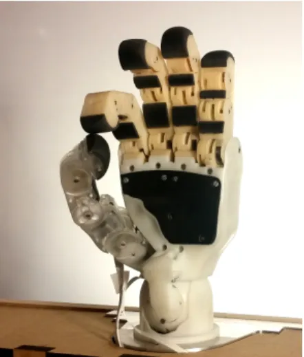
Fig. 1: ALdebaran Parallel HAnd (ALPHA) design.
on providing reliable grasping capabilities while humanoid robot hands target specific task services. To produce a useful robotic hand with the previously mentioned requirements and constraints, the main difficulty lies in finding the best trade-off between anthropomorphism and mechanical feasibility.
In literature, grasp-oriented robotics hands are often designed to mechanically self-adapt to different object shapes [1]. These hands are commonly called under-actuated and are characterized by transmission mechanisms which allow power distribution to fingers and phalanges even when some link motions are hindered by external forces. The term under-actuated is not always used by hand designers to identify self-adaptable mechanisms, creating ambiguities about its mean-ing. In this context, they are named self-adaptable to avoid confusion, leaving the sense of under-actuated to its classic connotation. A typical solution adopted by self-adaptable hands consists in placing single acting actuators in the palm or in the forearm and distributing its force to the fingertips via linkages or pulleys and cables. In these mechanisms, finger motions depend on the actuation forces, the restorative forces provided by elastic elements placed within fingers and to the external forces applied on phalanges. Their geometric parameters are challenging to design but, once achieved, self-adaptable hands provide simple and effective manipulators. To act against restoring forces within fingers, high reduction ratios are normally necessary [2], adding weight and often increasing the actuation noise. In addition, higher reduction ratios prevent easy backdrivability, fast motions and contact force estimation from motor current readings, imposing the need to add sensors for active impedance control. By properly distributing actuation forces among fingers,
self-adaptability can be extended among fingers to grasp a large variety of objects by mean of one actuation source [3]– [5], but it is inadequate to suggest and convey expressive gestures. To the authors’ opinion, for a minimal number of world-wide common gestures (such as pointing, “ok” and counting up to five) one DoF per finger and three for the thumb are required. Hence, at least seven actuators are needed for providing sufficient gesture-based communica-tion abilities. Differently from grasp-oriented hands, multi-purpose hands use a large number of actuators to drive most hand DoFs and couple the remaining DoFs with fixed transmission ratios [6]–[8]. The number varies according to the task to be performed and the context of application, leaving the artifacts under-actuated. Highly actuated designs provide astonishing performance but are heavy, expensive and often not self-contained [9]–[14]. However, prosthetic and humanoid robot hands must be lightweight, compact and proportional to the rest of the body. Current under-actuated hands with a reduced number of actuators present limited capabilities with respect to human hand dexterity and grasp performance [15]–[17]. With enough DoFs they can express basic gestures but they require more complex control strategies during grasping phases to firmly hold an object. Furthermore, they still need high reduction ratios to provide sufficient grasp force, preventing backdrivability, fast finger motions, sensor-less impedance control and increasing their price. RoboRay Hand [12] and Crawford et. al. [18] finger prototype combine self-adaptable and under-actuated kinematics by mean of separated actuation mechanisms. Both designs present a high number of actuators and never decou-ple the last two joints of the fingers. Another hybrid robotic hand is designed in [19], where two actuation mechanisms are used to allow either fast motion or large grasp force.
In this paper, a novel hybrid robotic hand is proposed. The adjective hybrid arises from the fact that the hand takes advantage of both self-adaptable and under-actuated hand performance by placing two distinct actuation systems in parallel, within the palm and the fingers. In this work, the two actuation systems coexist in a unique design thanks to an elastic transmission in the fingers. The first grants gesture capabilities but lacks adequate grasping forces. It is characterized by very low reduction ratios which reduce volume, weight, noise and cost and encourage backdrivability and sensor-less active compliance. The second actuation system provides the grasp force to the fingertips and im-plements self-adaptability among fingers and phalanges. In brief, thanks to the parallel actuation systems, the hand can perform common gestures with the first actuation system and grasp objects of different shapes with the second one.
This paper is organized as follows. Section II presents the mechanical design of the two actuation systems which coexist within the palm and the fingers. Section III presents the adopted low-level control strategies to provide safe human-robot interaction and limited grasp forces. Section IV analyzes the hand performance and validates its mechanical feasibility and design on the base of its gesture and grasping capabilities. Finally, Section V summarizes the main
contri-TABLE I: Off-the-shelf Maxon brushless DC motors.
Motor P [W] h [mm] τn [mNm] Weight*[g]
EC 14 flat 1.5 12 1.81 8
EC 45 flat 70 26.7 128 141
*weight of reduction mechanisms excluded.
TABLE II: Reduction ratios adopted in the e-motion actua-tion mechanism. Thumb RC abd/add Thumb RC flex/ext Thumb MCP Fingers MCP i 17.4:1 10.2:1 3.4:1 7.44:1
butions and results about the proposed robotic hand design, outlining possible future works and research directions.
II. MECHANICAL DESIGN
The hand kinematics is based on the design method proposed by [20] which preserves human hand proportions and dexterity by defining hand geometry (finger lengths, width, base placements), DoFs and range of motions. Its realization is illustrated in Fig. 1. Since the objective is to convey emotions through hand gestures and provide object shape adaptation during grasp, the two actuation systems are respectively called e-motion and grasp. They are embedded in the hand and the forearm and presented hereafter. A. E-motion actuation system
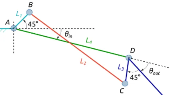
The first actuation system is characterized by seven EC 14 flat motors (Tab. I), one per finger and three for the thumb, placed in the palm with very low reduction ratios (Tab. II). Low reduction ratios reduce volume, weight, noise and cost. In addition, they provide high backdrivability and allow sensor-less active compliance control. The seven DoFs grant dexterity and gesture capabilities but lack in adequate grasping force (EC 14 flat, Table I). In order to perform gestures finger joints are coupled in a non-linear way. To do this, a linkage-based transmission mechanism appears to be the most interesting solution: more efficient than a gear train, with no potential leakages, and no pre-tensioning systems needed. Finger joints are coupled by the inverted 2D four-bar linkage shown in Fig. 2. It is designed to move output angles faster than the input one at the beginning of a closing motion and slower at the end of it. Each finger is driven by a series of two inverted four-bar linkages (Fig. 3), except for the thumb which presents only one coupling mechanism between its last two joints. The geometric parameters of the four-bar linkage are bounded by mechanical constraints. L4coincides with the
phalanx length while L3 is imposed equal to L1. The length
of L1 is bounded between avoiding collision of L4 with the
joint axis and remaining within the available space in the finger. Unconstrained parameters are chosen such that the fingers can be properly stretched and closed, i.e. the output angles must coincide with input ones (θin= θout) at the joint
limits (0◦and 90◦). This is obtained by imposing the angle between AB and the precedent phalanx and the angle between
DCand the successive phalanx equal to 45◦(Fig. 2) and the last bar length L2 to (L24+ 2L21)1/2.
Fig. 2: Four-bar linkage notations.
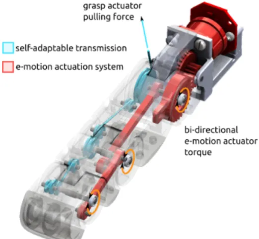
Fig. 3: E-motion actuation system.
B. Grasp actuation system
The second actuation system is composed by a single motor placed in the forearm, more powerful than the ones embodied in the palm (EC 45 flat, Table I). Its pulling force is transmitted to the fingertip through a series of cables and pulleys within the palm and the fingers. This actuation system is used instead of the first one to grasp objects that would be otherwise ejected. Indeed, it does not only strengthen the grip but also improves grasping performance by implementing self-adaptation among fingers and phalanges. This is achieved by distributing the actuation force to the digits according to their configuration and by replacing a rigid bar with an elastic element at each 4-bar linkage in the fingers. The last provides finger adaptation to the object shape and mechanical protection in presence of external forces applied to the phalanges. In addition, differently from classic self-adaptable finger mechanisms, in absence of external contacts at the fingers, passive elements do not oppose motor torques to recall fingers to straight configurations. In other words, stronger forces are provided to the grasp since only minor energy is lost in deviating the passive elements from their equilibrium positions.
Grasp actuation force is distributed to the finger bases through an adaptive transmission mechanism, embodied be-tween the e-motion actuators and the dorsal side of the palm, which guarantees self-adaptability among fingers, i.e. when one or more fingers are blocked the reminders are still free to move. The transmission mechanism consists of
a tree-structured composition of differential stages which respectively split one input force into two outputs. Inspired by the TUAT/Karlsruhe humanoid hand [21], the mechanism is mainly conceived to minimize static friction forces induced by contact surfaces and cable deflections. Its design is more efficient than the cable/pulley system proposed by [22] where large cable deviations increase friction losses. Its structure is composed by seesaw differential mechanisms with unconstrained input and output angles which reduce complexity, size, weight and costs thanks to the fact that less mechanical components are required. Similarly to mov-able pulleys, seesaw mechanisms are modeled as planar 2 DoFs bodies which can translate along the direction of the input force and rotate about the vector orthogonal to the plane. The mechanism geometric parameters (bar lengths, arm lengths, initial cable lengths and angles) are chosen to equally distribute the force among outputs when all fingers are open. Its differential stages present bars with approximately equal arms and large width, to explore finger workspaces with wider rotations rather than displacements that could not be attained within the palm space. Figure 4a shows the CAD model of the differential mechanisms in a generic configuration. To transmit the grasp force to the phalanges a tendon is routed from the finger base to the fingertip through a series of free wheel pulleys. To reduce friction losses, the cable path curvature is minimized and sliding surfaces are completely avoided. Small bearings are placed between pulleys to keep the cable tangent to them in any configuration. This guarantees a constant moment arm (configuration independent) that simplifies the relationship of joint, actuation and elastic torques. Figure 4b shows the cable routing in the fingers, which slightly differs in the Thumb, where the cable passes through the center of rotation of the first joint to avoid coupling between flexing and opposing motions (Fig. 6).
Finger self-adaptability by itself does not ensure stable grasps. Under-actuated phalanges might lose contact with the grasped object and lead to object ejection in certain cases. Grasp stability is studied at the level of a single finger and it is determined by the nature of its contact forces. Contact forces depend on the contact point positions, the joint configurations, the link lengths and the pulley radii. The first two depend on the object shape and the grasp type while the remainder are intrinsic to the finger design. Since link lengths are fixed by anthropomorphic constraints, pulley radii are the only mechanical parameters that are free to be tuned to minimize the probability of object ejection and improve grasping performance. They are optimized according to dif-ferent grasping indexes: grasp stability, contact robustness, force isotropy and palm opposition [1]. The first two have been evaluated within all joint RoM while the last two have been evaluated on a set of collected hand configurations, chosen in function of specific objects to grasp. The optimized pulley radii do not ensure stable grasps in every grasp state configuration, but theoretically increase the finger grasping capabilities by reducing the probability to eject known and unknown objects. To check whether unstable grasps end
(a) Tree-structured differential stages placed at the dorsal side of the palm.
(b) Cable routing within fingers.
(c) Elastomer bar buckling for self-adaptation.
Fig. 4: Grasp transmission mechanism.
up ejecting or holding the grasped object, the evolution of contact trajectories is estimated and analyzed. In particular, this is done for the set of objects required to be grasped when the initial grasp state configurations present at least one negative contact force.
C. Elastic transmission
Coexistence between the two actuation systems (figs. 5 and 6) is allowed by flexible bars embodied in the four-bar linkages of the e-motion transmission mechanism (patent pending n◦1656434). Elasticity is dimensioned to preserve the transmission coupling under a desired force threshold after which the bar buckles (Fig. 4c). This limit determines the switching factor between the two transmission mecha-nisms by opening and closing the finger kinematic loops. Forces exerted on the four-bar linkage bars are computed for a closing finger motion from a fully stretched configuration to a completely flexed one lasting 1 [s]. Calculations are performed by computing the Inverse Dynamic Model for closed loop mechanisms from which internal efforts caused by the finger dynamics and the kinematic closed loops can be explicitly determined (more details given in [23]). Forces at the bar are analyzed at the point of connection with the successive phalanx (Fig. 7). The axial force along the bars
Fig. 5: ALPHA finger design: e-motion and grasp transmis-sion mechanisms. The e-motion brushless DC motor, gears and elastic coupling bars are highlighted in red while the grasp cable and pulleys are presented in blue.
Fig. 6: ALPHA thumb design: e-motion and grasp trans-mission mechanisms. The three brushless DC motors and associated gears and the elastic coupling bar are highlighted in red while the grasp cable and pulleys are presented in blue.
varies from compression to extension according to the finger configuration. The bar is squeezed any time an external force tries to close the connected phalanx with respect to its coupled configuration. On the contrary, it is stretched when an external force pushes the successive phalanx to open. The maximum compression force experienced during the motion test drives the design of the elastomer bars. Elastic constants are sized to withstand the maximum compression force without buckling, in order to preserve finger coupling. Constraining the bar length, height and width (the first constrained by the finger geometry while the latter by the limited space) the elastomer Young’s Modulus (E) is adjusted to support the desired critical force by varying its material and Shore hardness. A high E coefficient implies a more rigid bar which buckles at stronger efforts and increases the opposition to the grasping force. In order to save energy the elastic force has to be minimal, but still compensate finger dynamic efforts. The desired modulus (E∗) is determined according to Euler’s column buckling formula:
E∗≥ F
∗(K bL0)2
Fig. 7: Connection points at which dynamic compres-sion/extension forces are analyzed during finger motions.
where F∗ is an arbitrary critical force (higher than finger dynamic effects), Kbis equal to 1, since the bar is connected to two pivoting points, L0 is the bar length at rest and I is
the weakest area moment of inertia of the bar cross section. Mechanically constrained shapes of the elastomer bars are easily obtained by high-precision laser cutting.
III. CONTROL STRATEGIES
The sensory apparatus of the hand is simplified to the minimum set of sensors necessary to control finger motions and grasp. No tactile sensors are applied on the fingertips, and there are no pressure sensors on the palm and phalanges, no torque sensors and no cable tension sensors. Each e-motion motor is controlled at 1 [KHz] by a standard PD position controller, a torque feed-forward and an impedance controller [24]. Positions are measured through AMS AS5048 magnetic rotary encoders (14-bit) which provide accurate high-resolution absolute angular positions of each motor. Joint velocities are estimated from encoder position mea-surements with linear tracking loops (a type of low-pass filter). The torque feed-forward is added to compensate the dynamic effects of finger motions in order to improve the tracking performance all along the motion range. Dynamic compensation is remotely computed on a central board (ATOM E3845) on the base of measured positions and de-sired velocities and accelerations, and is sent to the respective motor boards every 20 [ms]. The impedance controller offers safe human-robot interaction by adding position and velocity deltas to initial set-points in order to provide a mass-spring-damper behavior to the output as soon as external torques are detected. These are computed as the difference between the theoretical (Inverse Dynamic Model) and estimated joint torques. More specifically, since no torque sensors are used, estimated joint torques are obtained from measured motor torques through accurate gearbox models, which take into account mechanical effects such as bearing friction, mesh friction and power flow direction according to gear ratio and efficiency [25]. Measured motor torques are indirectly evaluated through current readings (10-bit ADC) based on sensing resistors in series with the motor phases. A fine output torque control is mandatory to efficiently exploit actuator torques (Table I). This is done by mean of the Field oriented Control [26] implemented on the motor boards. Furthermore, the undesired cogging torque characteristic of BLDC motors [27] is identified and compensated [28].
At high level, the hand is controlled by alternating the activation of the two actuation systems. To perform gestures and to pre-shape the hand before grasping, the structure is
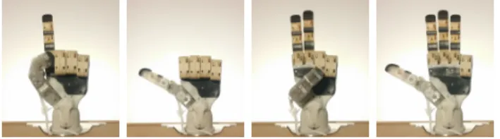
Fig. 8: Examples of feasible hand gestures.
purely driven by the e-motion actuation mechanism. On the contrary, if grasp is desired, the grasp motor is activated and e-motion motors are switched off when fingers enter in contact with the object. To restore phalanx couplings and to release the object, the grasp motor is turned off and the cable released.
IV. VALIDATION AND DISCUSSION
Hand performances are experimentally validated on the base of gesture and grasping capabilities of the prototype. The prototype weighs 540 [g], considering the whole hand plus the motor in the forearm and excluding the non-optimized electronics located outside of the palm.
Gestures and grasping capabilities are tested by controlling the prototype through a data-glove (5DT 14 ultra) composed of 14 optical sensors - 8 of which are used in practice: 4 for the fingers and 4 for the thumb (2 non-linearly combined to drive the flexing motion of the first joint). At first, it is checked if the hand achieves specific hand gestures for which it has been explicitly designed for [20]. These gestures consist of common signs that are normally used to provide a service (cupped hand and pointing), convey information (counting up to five and “telephone”), spring emotions (“ok” and “thumb-up”) and express personal feelings (“twiddling thumbs” and a closed fist). The ones that can be done by one limb are successfully performed by the hand (a collection of these is shown in Fig. 8) while the ones which require two hands, such as twiddling the thumbs or mimicking the shape of a heart, cannot be effectively tested.
Grasp capabilities are explored on the base of the compre-hensive grasp taxonomy of the human hand presented in [29]. The identified 33 grasp types are tested with both actuation mechanisms to analyze their performance and limits. Tests are conducted by two subjects. One remotely controls the hand while the other provides and fetches objects to the prototype. The objects are light (the heaviest weighs 91 [g]) 3D printed ABS parts, filled at 15% of their volume, which respect the proportions of the items proposed in the taxonomy. For power and intermediate grasps, remote control is performed via the data-glove to accelerate grasp phases. On the contrary, precision grasps are executed on the base of stored force closure configurations, due to the kinematic differences between the human hand and the robotic one. Experimental tests show that the e-motion actuation system can perform 90% of grasp types (3% failed due to un-reachable force closure and 6% failed because of the object weight amount and distribution) while the grasp actuation system achieves 39% of them (94% of the failed grasp types
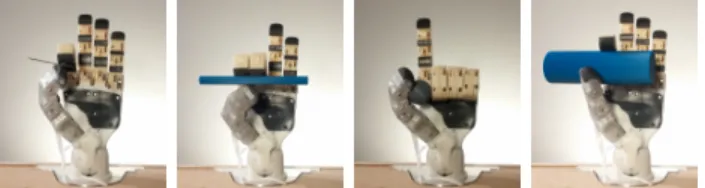
(a) (b) (c) (d)
Fig. 9: Examples of grasp transition between the two actu-ation systems. The first row shows the initial grasp config-urations achievable with the e-motion actuation. The second row shows the final grasp state once the motor in the forearm is activated.
Fig. 10: Examples of grasp types that can be achieved by the grasp actuation mechanism.
involve pads and 57% involve the hand side in opposition). This confirms that more DoFs allow a larger hand dexterity and shows that one motor can grasp different objects by bringing them toward the palm. This is clearly shown in Fig. 9 where objects are initially grasped with the e-motion actuation mechanism and then seized by the grasp actuation mechanism, by turning off the first and activating the second. A high success rate of the e-motion system results from the fact that graped objects are light and that force closure has been achieved by visual feedback (some examples shown in Fig. 11). In practice, however, the e-motion actuation mech-anism can grasp a very limited number of objects, due to the reduced grasp force (about 0.8 [N]) and, more importantly, due to the lack of appropriate perception capabilities (e.g. tactile sensing) and of complex grasp planning strategies. A more cost-effective and easy-to-control solution is offered by the grasp actuation mechanism which does not require any grasp planning and develops grasp forces up to 3.6 [N]. Indeed, this mechanism is able to perform all grasp types which use palm in opposition (some examples shown in Fig. 10) and adapts to the object shape to secure the grasp (e.g. on the power grasp of a disk - Fig. 9a). Only one grasp type (Index Finger Extension [29]) which involves the palm cannot be achieved, due to the index finger which acts as a second virtual finger rather then a third. This is due to the differential mechanism which autonomously balances forces among fingers.
Fig. 11: Examples of grasp types that can be achieved by the e-motion actuation mechanism.
V. CONCLUSIONS AND FUTURE WORKS
In this paper a human-inspired humanoid robot hand to gesture and grasp has been presented. Its design is driven by two parallel actuation systems based on an elastic trans-mission mechanism which offers sufficient coupling rigidity to perform fast finger motions and limited restoring force to allow finger adaptation with reduced actuation energy. The first actuation system ensures gesture capabilities but lacks adequate grasping forces. It is characterized by very low reduction ratios which reduce volume, weight, noise and cost and encourages backdrivability, fast motions and sensor-less active compliance. The second provides adequate grasp force to the fingertips to grasp light objects and implements self-adaptability among phalanges and fingers. Its prototype has been presented and analyzed to confirm design feasibility, functional capabilities and possibility to be embodied on a humanoid robot.
Future work includes the optimization of electronic ponent sizes and shapes. Currently most of electronic com-ponents are placed outside the hand and a part of them are planned to be integrated in the palm for a proper integration on a humanoid robot. Finally, postural synergies should be implemented [30] to simplify grasp prshaping with the e-motion actuation system.
ACKNOWLEDGMENT
The hand prototype has been realized thanks to the expert help of Florian Armange and Thibault Davasse who con-tributed in the implementation of its low-level control and mechanical design.
REFERENCES
[1] L. Birglen and C. Gosselin, “Kinetostatic analysis of underactuated fingers,” IEEE Transactions on Robotics and Automation, vol. 20, no. 2, pp. 211–221, April 2004.
[2] E. Matheson, Y. Aoustin, E. Le Carpentier, A. Leon, and J. Perrin, New Trends in Medical and Service Robots, P. Wenger, C. Chevallereau, D. Pisla, H. Bleuler, and A. Rodi´c, Eds. Springer, 2016.
[3] M. G. Catalano, G. Grioli, E. Farnioli, A. Serio, C. Piazza, and A. Bicchi, “Adaptive synergies for the design and control of the Pisa/IIT SoftHand,” The International Journal of Robotics Research, vol. 33, no. 5, pp. 768–782, 2014.
[4] L. U. Odhner, L. P. Jentoft, M. R. Claffee, N. Corson, Y. Tenzer, R. R. Ma, M. Buehler, R. Kohout, R. D. Howe, and A. M. Dollar, “A compliant, underactuated hand for robust manipulation,” The International Journal of Robotics Research, vol. 33, no. 5, pp. 736– 752, 2014.
[5] L. Birglen and C. M. Gosselin, “Force Analysis of Connected Differ-ential Mechanisms: Application to Grasping,” Int. J. Rob. Res., vol. 25, no. 10, pp. 1033–1046, Oct. 2006.
[6] A. Schmitz, U. Pattacini, F. Nori, L. Natale, G. Metta, and G. Sandini, “Design, realization and sensorization of the dexterous iCub hand,” in 10th IEEE-RAS International Conference on Humanoid Robots (Humanoids), Nashville, TN, USA, 2010, pp. 186–191.
[7] L. Bridgwater, C. Ihrke, M. Diftler, M. Abdallah, N. Radford, J. M. Rogers, S. Yayathi, R. S. Askew, and D. Linn, “The Robonaut 2 hand - designed to do work with tools,” in IEEE International Conference on Robotics and Automation (ICRA), St. Paul, MN, USA, 2012, pp. 3425–3430.
[8] G. Palli, C. Melchiorri, G. Vassura, U. Scarcia, L. Moriello, G. Berselli, A. Cavallo, G. De Maria, C. Natale, S. Pirozzi, et al., “The DEXMART hand: Mechatronic design and experimental evaluation of synergy-based control for human-like grasping,” The International Journal of Robotics Research, vol. 33, no. 5, pp. 799–824, 2014.
[9] Shadow hand. Website. Shadow Robot Company
LTD. (Accessed 27 Feb 2016). [Online]. Available:
http://www.shadowrobot.com/products/dexterous-hand/
[10] H. Liu, K. Wu, P. Meusel, N. Seitz, G. Hirzinger, M. Jin, Y. Liu, S. Fan, T. Lan, and Z. Chen, “Multisensory five-finger dexterous hand: The DLR/HIT Hand II,” in IEEE/RSJ International Conference on Intelligent Robots and Systems, Nice, France, 2008, pp. 3692–3697. [11] T. Seki, T. Nakamura, R. Kato, S. Morishita, and H. Yokoi,
“De-velopment of five-finger multi-DoF myoelectric hands with a power allocation mechanism,” in IEEE International Conference on Robotics and Automation (ICRA), 2013, pp. 2054–2059.
[12] Y.-J. Kim, Y. Lee, J. Kim, J.-W. Lee, K.-M. Park, K.-S. Roh, and J.-Y. Choi, “RoboRay hand: A highly backdrivable robotic hand with sensorless contact force measurements,” in Robotics and Automation (ICRA), 2014 IEEE International Conference on, May 2014, pp. 6712– 6718.
[13] Servo-electric 5-Finger Gripping Hand. Website. Schunk GmbH
& Co. KG. (Accessed 25 Feb 2016). [Online].
Avail-able: http://mobile.schunk-microsite.com/en/produkte/produkte/servo-electric-5-finger-gripping-hand-svh.html
[14] J. Martin and M. Grossard, “Design of a fully modular and backdriv-able dexterous hand,” The International Journal of Robotics Research, vol. 33, no. 5, pp. 783–798, 2014.
[15] Z. Kappassov, Y. Khassanov, A. Saudabayev, A. Shintemirov, and H. Varol, “Semi-anthropomorphic 3D printed multigrasp hand for industrial and service robots,” in IEEE International Conference on Mechatronics and Automation (ICMA), 2013, pp. 1697–1702. [16] IH2 AZZURRA series. Website. Prensilia Srl. (Accessed 02 Feb
2016). [Online]. Available: www.prensilia.com
[17] K. Kaneko, F. Kanehiro, M. Morisawa, T. Tsuji, K. Miura, S. Nakaoka, S. Kajita, and K. Yokoi, “Hardware improvement of Cybernetic Human HRP-4C for entertainment use,” in Intelligent Robots and Systems (IROS), 2011 IEEE/RSJ International Conference on, Sept 2011, pp. 4392–4399.
[18] A. Crawford, J. Molitor, A. P´erez Gracia, S. Chiu, et al., “Design of a robotic hand and simple EMG input controller with a biologically-inspired parallel actuation system for prosthetic applications,” in ASME 2010, IDETC/CIE 2010.
[19] Y. Lee and C. Cho, “A biomimetic hand employing a dual actuation scheme,” Journal of mechanical science and technology, vol. 26, no. 12, pp. 4131–4139, 2012.
[20] G. Cerruti, D. Chablat, D. Gouaillier, and S. Sakka, “Design method for an anthropomorphic hand able to gesture and grasp,” in Robotics and Automation (ICRA), 2015 IEEE International Conference on, May 2015, pp. 3660–3667.
[21] N. Fukaya, S. Toyama, T. Asfour, and R. Dillmann, “Design of the TUAT/Karlsruhe humanoid hand,” in Proceedings IEEE/RSJ Interna-tional Conference on Intelligent Robots and Systems (IROS 2000). Takamatsu, Japan, vol. 3, 2000, pp. 1754–1759 vol.3.
[22] C. Gosselin, F. Pelletier, and T. Laliberte, “An anthropomorphic underactuated robotic hand with 15 dofs and a single actuator,” in Robotics and Automation, 2008. ICRA 2008. IEEE International Conference on, May 2008, pp. 749–754.
[23] G. Cerruti, “Design and Control of a Dexterous Anthropomorphic Robotic Hand,” Ph.D. dissertation, Ecole Centrale de Nantes, 2016. [24] D. Tsetserukou, R. Tadakuma, H. Kajimoto, N. Kawakami, and
S. Tachi, “Towards Safe Human-Robot Interaction: Joint Impedance Control of a New Teleoperated Robot Arm,” in Robot and Human interactive Communication, 2007. RO-MAN 2007. The 16th IEEE International Symposium on, Aug 2007, pp. 860–865.
[25] C. Pelchen, C. Schweiger, M. Otter, Q. Rgholfd, and R. U. Ss, “Modeling and simulating the efficiency of gearboxes and of planetary gearboxes,” 2002.
[26] J. John, S. Kumar, and B. Jaya, “Space Vector Modulation based Field Oriented Control scheme for Brushless DC motors,” in Emerging Trends in Electrical and Computer Technology (ICETECT), 2011 International Conference on, March 2011, pp. 346–351.
[27] A. Hartman and W. Lorimer, “Cogging torque control in brushless dc motors,” Incremental Motion Control Syst. And Devies, 29Th Annu. Syrup. Proc, pp. 237–243, 2000.
[28] M. Piccoli and M. Yim, “Cogging torque ripple minimization via position-based characterization,” in Proceedings of robotics: science and systems, 2014.
[29] T. Feix, R. Pawlik, H.-B. Schmiedmayer, J. Romero, and D. Kragic, “A comprehensive grasp taxonomy,” in Robotics, Science and Systems: Workshop on Understanding the Human Hand for Advancing Robotic Manipulation, 2009, pp. 2–3.
[30] F. Ficuciello, A. Federico, V. Lippiello, and B. Siciliano, “Synergies Evaluation of the SCHUNK S5FH for Grasping Control,” in Advances in Robot Kinematics : Proceedings of the 15th international conference on Advances in Robot Kinematics, 2016, pp. 229–237.