To cite this version :
David, Laurent and Mehel , Amine and Tarrade, Laurent and Texier, Alain and Larinier, Michel Modification of vortex structures in fishways by cylinder adjunction. (2009) In: 13th International Symposium on Flow Visualization - ISFV13, 01 July 2008 - 04 July 2008 (Nice, France).
Open Archive TOULOUSE Archive Ouverte (OATAO)
OATAO is an open access repository that collects the work of Toulouse researchers and makes it freely available over the web where possible.This is an author-deposited version published in : http://oatao.univ-toulouse.fr/ Eprints ID : 11264
Any correspondance concerning this service should be sent to the repository administrator: [email protected]
MODIFICATION OF VORTEX STRUCTURES IN
FISHWAYS BY CYLINDER ADJUNCTION
L. David*, A. Mehel*, L. Tarrade*, A. Texier*, M. Larinier** *Laboratoire d’Etudes Aérodynamiques
Université de Poitiers, CNRS, ENSMA Bd Marie et Pierre Curie
86962 Futuroscope Cedex (France)
**IMFT, allée du professeur Camille Soula, 31400 Toulouse France
KEYWORDS:
Main subject(s): flow control, environnement application,
Fluids: Water Visualization method(s): PIV, ADV, particle visualization
Other keywords: unsteady flow, cylinder, vertical slot fishway, turbulent flow,
recirculation, shear layer, jet
ABSTRACT : The improvement of devices that allow the upstream migration of fishes through engineering constructions or natural obstructions in rivers is now a real priority to maintain the biodiversity. Vertical slot fishways are commonly used and are very effective in ensuring unhindered passage of the species of large size fishes [1]. The flows within these hydraulic structures are turbulent [2] and present unsteady vortex dynamic in relation to the geometric parameters of the pools (slopes, flow discharges and pool widths). The modes of locomotion of the fish depend to the species and are the object of several recent studies [3]. The fishes use the fluid motion generated inside the pools to the propulsion and to move easily upstream in the fishway. Nerveless the species with small sizes have some difficulties to upstream migrate because the kinematic energy and the velocity are too large for them. An experimental study is undertaken to characterize the turbulent flow for various configurations of vertical slot fishways and to determine how their characteristics might be modified in order to facilitate the passage of small species. Particle Image Velocimetry is achieved to analyze the effects of vertical cylinders within the pools on the dimensions of recirculation zones and the turbulence intensity. Mean velocity and fluctuation measurements inside a pool with and without cylinder are compared. The unsteady behaviours and the vortex flapping are examined.
1 INTRODUCTION
Vertical slot fishways have been built to facilitate the upstream fish migration and are currently used in many countries. Water runs downstream this channel through a series of vertical slots from one pool to the next one below. The water flow forms a jet as it goes through the slot and the energy is dissipated by jet mixing in the pool [4]. The baffles are so shaped that part of the flow is turned back upstream to create recirculation regions in the pools where the fish would rest to recover their swimming ability before ascending the fishway through the slots at any depth it chooses. The fish locomotion inside the pools depends of their capacities of swimming and for small species, the vortices and recirculation zones can be a trap. The jet could have a highest energy to allow the migration of the fish. The
unsteady flow patterns are very important in order to guide the fish and make possible its way along the structure. Previous studies have allowed the understanding of the mean characteristics of the flow for different parameters as the flow rate, the pool width, the channel slope [5][6][7]. The flow for various configurations of vertical slot fishways is limited to two principal topology models according to the ratio length/width of the pool. The first which occurred for the higher width is composed of two great recirculation areas located on each side of the jet leaving the slot. The second occurred when the width is lower. The large recirculation area was then divided by the jet hitting the side wall, into two swirling cells, one of which was located at the upstream corner of the pool and the other along the large baffle. A third swirl then occupied the convex part of the jet. Depending on the channel slope, the intermediate pool widths generated one or other of the models. For these two topologies, the flow within the pool was rather two-dimensional so the fish [8], which swim up the vertical slot, encounter the same characteristics at any depth of the flow from the bottom to the water surface. Moreover a discharge variation caused a variation of the water depth in the fishway without modifying the flow patterns. Velocities increased with the channel slope. The insertion of vertical obstacles placed at the slot exit allows to reduce the recirculation and to attenuate the shear layers at the jet boundaries. The velocities in the principal flow are within the swim capacities of the small fish and the swirl created downstream from the cylinders provides rest area [9]. These first results are verified in this paper by velocity measurements. The unsteady behaviors of the flow inside the pools is also analyzed by time resolved sequences and linked to the displacement of the fishes.
2 EXPERIMENTAL SETUPS
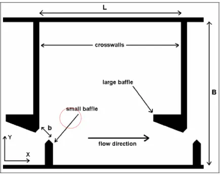
A physical model, related to the prototype by the Froudian similitude, of geometrical scale ¼ is used for this experimental study. This model has average characteristics of several vertical slot fishways built in France. The velocity scale is 1/2 and the discharge scale is 1/32. The width of the slot is b = 0.075 m. The vertical slot fishway model consists of five pools, L = 0.75 m long and H = 0.55 m deep (Fig.1). The width of each pool has been limited to two values: B = 0.675 and 0.50m (Fig.2) which correspond to the full scale to 2.7 and 2m. The channel slope can take three values: I = 5, 10 and 15 %. The crosswalls between the pools are perfectly vertical for a channel slope I = 10 %. The flow discharges has been fixed to Q=23 L/s which corresponds to a flow discharges to 736 L/s at the scale 1. Variation of flow discharges modifies only the water depth. The discharge velocities in the slot is respectively Vd= 0.72, 0.94 and 1.09 m/s for the three
channel slope I = 5, 10 and 15 %. The equivalent Reynolds numbers, calculated with the slot width b and the discharge velocities in the slot Vd are respectively Re= 60600, 79100 and 91800 according to the slope.
The experimental measurements were taken in the third pool in order to ensure an established symmetrical flow. The X-axis is in the longitudinal direction and the Y-axis is in the transverse direction of the fishway. The XY plane is parallel with the channel bed. All the geometric dimensions are multiplied by 4 to obtain the full scale and the velocities are multiplied by 2 to have the full scale or are normalized by the discharge velocities in the slot Vd. The full scale is significant for this application to rely the velocity and the
capacities of the fishes for the locomotion. The cylinder placed in the pool has a diameter of one slot and its center is placed at X = 2.1b and Y = 3.1b. Such a location of the cylinder significantly influenced the flow pattern by deviating the jet and shear layer and reducing the recirculation currents.
Fig. 2 - Pool configuration
Velocity measurements were taken by means of Particle Image Velocimetry (PIV) in one plane parallel with the channel bed of the fishway (Z=15 cm). The acquisition and treatment PIV system is composed of a laser lighting a flow section, a camera system and a synchronization system. The HIRIS 2.1 software allows to synchronize the laser and the cameras. A laser Nd-Yag double cavity Spectra-Physics (2x180 mJ) has been used to highlight a flow section seeded by hollow glass particles of 11 μm diameter. The frequency of each cavity is 10 Hz and the wavelength is 532 nm. The beams coming from the two cavities are directed towards a system of double lens system making it possible to produce narrow laser sheets which have a thickness of about 1.5 mm. In order to record the successive images of the flow, two cameras JAI are used with objectives of 50 mm and placed in parallel to visualize the whole pool. The resolution of these cameras is 1600x1200 pixels², coded on 8 bits. The cameras make it possible to acquire two successive images of the flow separated by a very short time Δt (between 3000 and 4000 μs) which is generated between the two cavities of the laser. Davis 7.2 software (Lavision) computes cross-correlation between the successive images and postprocessing on the calculated data. An initial interrogation area of 64x64 pixels², a final interrogation area of 32x32 pixels² with an overlap of 50 % and window deformation are used to compute the cross-correlation. For each camera, 1000 double image acquisitions (separated by T = 100 ms) allow to obtain 1000 instantaneous velocity fields. At each time, the two velocity fields calculated are jointed in order to have the complete velocity field of the pool. Statistics as mean, root mean square or spatio-temporal correlation are calculated. Velocity amplitude, vorticity, streamlines are also extracted to follow the fluid motion and their topologies. Proper Orthogonal Decomposition is also applied to the set of the velocity fields to highlight the main vortex structures or the more energetic and to follow in times the unsteady behaviors of the flow inside the pool.
3 RESULTS
3.1 Mean flow description
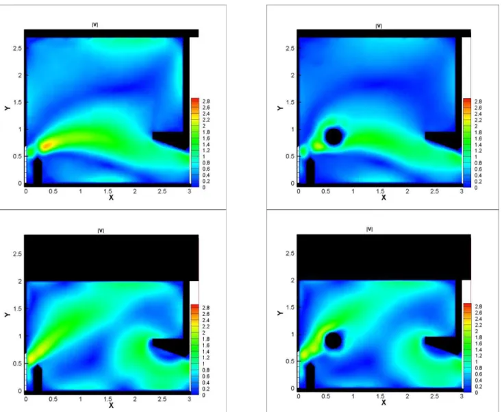
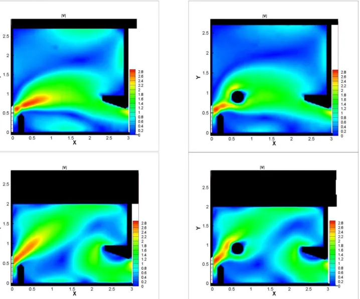
The flow with and without cylinder has been studied for the two typical width of the pool B=2.7 m et B=2m [9] and for the three slopes I=5, 10 et 15%. The characteristics of the mean flow are at first considered, in particular the mean velocity, the root mean squares of the different components, the turbulent intensity and the streamlines (Fig.5). For the two configurations with and without cylinder, the flow in a pool is mainly composed of three important areas: a principal jet caused by the slot, passing through the pool with decreasing velocity and two large recirculation zones generated on each side of this principal flow. The recirculations around an axis perpendicular to the channel bed allow for dissipation of the jet energy in each pool. Swirling cells of variable sizes, created by the principal recirculations, occur in all the corners of the pool, due to the velocity differential between the recirculating flow and the zero velocities on the wall. Two different flow patterns occur according to the ratio length/width of the pool.
The first flow pattern is for the largest width (B=2.7m) with and without the cylinder. The principal flow leaving the slot enters the pool as a curved jet which opens out before converging towards the following slot. The jet creates on a side, between the large baffles, an important recirculation area occupying roughly half of the pool surface. On the other side of the principal flow, a swirling zone of smaller size, rotating in the opposite sense to the preceding one, is generated between the small wall deflectors. The highest velocities are found in the jet, at a maximum when leaving the slot and decreasing progressively as the flow enters the pool while the lowest values are found in the recirculation areas (Fig.3 and Fig.4). The great difference between the configuration without and with the cylinder is a small curvature of the jet around the cylinder and globally the mean amplitude velocity is reduced in the whole pool. A second flow pattern occurs for the pools of the low width (B=2m): the jet has a very curved form and directly hits the opposite side wall (Fig.5). Two large contra-rotating swirls are then generated in the corner upstream of the pool and in the convex part of the jet and a smaller one occurs close to the large baffle. The reduction in width of the pool changes the dimensions and the shapes of the swirling cells: the area of principal recirculation occurring for the first flow pattern is divided into two small swirls. The first is moved towards the upstream corner of the pool with a reduction in its surface area compared to the first pattern and the second is pushed back along the large deflector.
I=5%, B=2.7m I=10%, B=2.7m I=15%, B=2.7m
I=5%, B=2.7m, 1 Cylinder I=10%, B=2.7m, 1 Cylinder I=15%, B=2.7m, 1 Cylinder
I=5%, B=2 m, I=10%, B=2 m, I=15%, B=2 m,
I=5%, B=2 m, 1 Cylinder I=10%, B=2 m, 1 Cylinder I=15%, B=2 m, 1 Cylinder Fig. 5 – Streamlines of the two configurations and for the 3 slopes with and without cylinder.
On the other side of the flow, the vortex tends to occupy the open space left in the convex part of the curved jet. It contracts in the longitudinal direction and is stretched in the transverse direction. Its size relative to the pool surface area increases. The velocities are high in the principal flow, at a maximum in the slot, while the values are low in the centre of the large swirls, creating zones of strong velocity gradients on the edges of the jet (Fig.3 and Fig.4). The effect of the cylinder is an early deviation of the jet in the bottom part of the pool and a small reduction of the vortex installed in the convex part of the flow close to the small baffle.
For all the fishway configurations studied, the slope variation does not generate different flow patterns: the two large countra-rotating cells are found on each side of the principal jet. Thus when the slope increases, the jet widens slightly whereas the sizes of the recirculation zones are reduced slightly (Fig.5).
3.2 Unsteady flow description
The flow in a vertical slot fishway (slope I = 10%, B = 2.7 m, Q = 736 L/s) is clearly unsteady (Fig.6). The jet beats alternatively from the left to the right (while looking towards the downstream direction), under the joint effects of the discontinuous high speeds inside the jet and the principal recirculations which it feeds by fluid friction. Depending on whether the jet beats on one side or the other, it feeds the recirculation zone located between the lateral deflectors or that located between the central deflectors. When the jet resulting from the slot is strong (phase a), it widens and tends to be directed towards its left, while looking towards the downstream direction. An important part of this one then feeds the higher swirl between the central deflectors which then occupies a great part of the pool volume, whereas the other part of the jet feeds the following slot and in a thinner way the lower swirl located between the side deflectors.
Phase a Phase b
Phase c Phase d
The important quantity of fluid which penetrates the higher vortex (phase b) deforms this vortex which moves towards an intermediate wall of the basin close to the central deflector. The flow is unstable: the swirling cores of the two principal cells tend towards "wells" (stronger 3D aspect). The cells compress the jet (phase c), a part of the fluid feeding the higher cell is “directly evacuated” towards the following slot. Consequently, positive and negative transverse velocities alternate in the jet (phase d, phenomenon measured at the point X = 2.21 m, Y = 1.15 m); its downstream extremity is thinned down and it feeds the following slot in a more direct manner. The jet is in this phase is less strong; the higher swirl less nourished lets his opposite lower swirl benefits from flow until the velocities at the exit of the slot increase again to maintain the beat.
With the adjunction of the cylinder, this unsteady behaviour is always present and reinforced (Fig.7). The main vortex structure oscillates between upstream zones to downstream zones in the pool. One core or two cores exist and merge together with the motion of the vortex. A small vortex appears sometimes just at the entrance of the pool above the jet. The swirl structure close to the small baffle is composed of one, two or three vortices which increase or merge with the beat of the jet. The vortices with one cylinder are more numerous and their sizes are smaller than for the flow without cylinder.
Fig.7: Different phases of the beat of the flow for the first pattern with one cylinder
For the second flow model (Fig. 8) (B = 2 m, I = 10%) the beat of the jet is less marked than in the first model. The discontinuous entry of fluid at high speed within a basin results in a stretching of the jet. When the velocities remain high it clearly impacts on the side wall which it skirts to the central deflector (phase a). The important generated "skirting" feeds the zone of recirculation in its convex part by stretching it. When the jet is less strong (phase b), its impact zone on the side wall shifts upstream, the skirting of the central deflector is less marked, the principal swirl is more reduced and the flow converges more directly towards the following slot. When the jet becomes strong again, the process tends towards phase a again.
The flow is more affected with the presence of the cylinder (Fig.9). The flow always impacts the top wall but the principal vortex close to the small deflector is decomposed sometimes in one, two or three vortices. These structures are less steady and are influenced by the shear layer generated by the cylinder. The
downstream jet is alimented by the main jet or by the vortex structures. The size and the location of the vortices are linked to the beat of the jet.
Phase a Phase b
Fig.8: Different phases of the beat of the flow for the second pattern
The area behind the small baffle is alternatively at the rest or submitted to a clockwise or anticlockwise swirl which favours the displacement of the fish.
Fig.9: Different phases of the beat of the flow for the second pattern with the cylinder
4 CONCLUSION
The influence of the adjunction of a cylinder in a flow for vertical slot fishways has been studied for two main configurations B = 2.7 and 2 m. The presence of the cylinder has generated low differences on the mean flow comparing to the same configurations without cylinder. The variation of the slopes seems also to don’t modify two principal topology models according to the ratio length/width of the pool with the cylinder. The unsteady behavior of the flow has been shown. The beat of the jet inside the pool favors the migration of the fish. The main jet or the main structure are discharging alternatively downstream for the
largest pool. For the pool of width 2 m, the beat is less pronounced. The adjunction of the cylinder increases for the both cases the number of vortices inside the pool and decreases the size of each. Sequences of merging or separation appear irregularly and increase the phenomenon of beating. These configurations seem more favorable for the migration of small fishes [2].
References
1. Larinier M, Travade F and Porcher J P. Fishways: biological basis, design criteria and monitoring. Bulletin Français de la Pêche et de la Pisciculture, 2002.
2. Tarrade L., Texier A., David L., Pineau G., Larinier M. Experimental approach to adapt the turbulent flow in the vertical slot fishways to the small fish species. Journal Hydrobiologia (in press) 2008.
3. Triantafyllou M., 2007: Special issue: Animal locomotion: The hydrodynamics of swimming. Experiments in Fluids Volume 43, 5.
4. Pena L, Cea L and Puertas J. An experimental analysis in vertical slot fishways. Fifth International Symposium on Ecohydraulics, Madrid, pp 881-888, 2004.
5. Puertas J, Pena L and Teijeiro T. An experimental approach to the hydraulics of vertical slot fishways. Journal of Hydraulic Engineering, Vol. 130, No. 1, pp 10-23, 2004.
6. Rajaratnam N, Van der Vinne G and Katopodis C. Hydraulics of vertical slot fishways. Journal of Hydraulic Engineering, Vol. 112, No. 10, pp 909-927, 1986.
7. Rajaratnam N, Katopodis C and Solanski S. New designs for vertical slot fishways. Journal of Hydraulic Engineering, Vol. 19, No. 3, pp 402-414, 1992.
8. Wu S, Rajaratnam N, and Katopodis C. Structure of flow in vertical slot fishway. Journal of Hydraulic Engineering, Vol. 125, No. 4, pp 351-360, 1999.
9. Tarrade L., Texier A., David L., Pineau G., Larinier M., an experimental study of turbulent flow in vertical slot fishways. 12th International Symposium of Flow Visualization, Göttingen (Germany), 2006.
Acknowledgments
The authors kindly acknowledge Voies Navigables de France providing the grant of this study.
Copyright Statement
The authors confirm that they, and/or their company or institution, hold copyright on all of the original material included i n their paper. They also confirm they have obtained permission, from the copyright holder of any third party material included in their paper, to publish it as part of their paper. The authors grant full permission for the publication and distribution of their paper as part of the ISFV13/FLUVISU12 proceedings or as individual off-prints from the proceedings.