HAL Id: hal-01758178
https://hal.archives-ouvertes.fr/hal-01758178
Submitted on 4 Apr 2018
HAL is a multi-disciplinary open access
archive for the deposit and dissemination of
sci-entific research documents, whether they are
pub-lished or not. The documents may come from
teaching and research institutions in France or
abroad, or from public or private research centers.
L’archive ouverte pluridisciplinaire HAL, est
destinée au dépôt et à la diffusion de documents
scientifiques de niveau recherche, publiés ou non,
émanant des établissements d’enseignement et de
recherche français ou étrangers, des laboratoires
publics ou privés.
Sensitivity Analysis of the Elasto-Geometrical Model of
Cable-Driven Parallel Robots
Sana Baklouti, Stéphane Caro, Eric Courteille
To cite this version:
Sana Baklouti, Stéphane Caro, Eric Courteille. Sensitivity Analysis of the Elasto-Geometrical Model
of Cable-Driven Parallel Robots. Gosselin C.; Cardou P.; Bruckmann T.; Pott A. Cable-Driven Parallel
Robots, 53, pp.37-49, 2018, 978-3-319-61431-1. �10.1007/978-3-319-61431-1_4�. �hal-01758178�
Model of Cable-Driven Parallel Robots
Sana Baklouti, St´ephane Caro and Eric CourteilleAbstract This paper deals with the sensitivity analysis of the elasto-geometrical model of Cable-Driven Parallel Robots (CDPRs) to their geometric and mechanical uncertainties. This sensitivity analysis is crucial in order to come up with a robust model-based control of CDPRs. Here, 62 geometrical and mechanical error sources are considered to investigate their effect onto the static deflection of the moving-platform (MP) under an external load. A reconfigurable CDPR, named ``CAROCA´´, is analyzed as a case of study to highlight the main uncertainties affecting the static deflection of its MP.
1 Introduction
In recent years, there has been an increasing number of research works on the subject of Cable-Driven Parallel Robots (CDPRs). The latter are very promising for engineering applications due to peculiar characteristics such as large workspace, simple structure and large payload capacity. For instance, CDPRs have been used in many applications like rehabilitation [1], pick-and-place [2], sandblasting and painting [4, 3] operations.
Many spatial prototypes are equipped with eight cables for six Degrees of Freedom (DOF) such as the CAROCA prototype, which is the subject of this paper.
Sana Baklouti
Universit´e Bretagne-Loire, INSA-LGCGM-EA 3913, 20, avenue des Buttes de C¨oesmes, 35043 Rennes, France, e-mail: [email protected]
St´ephane Caro
CNRS, Laboratoire des Sciences du Num´erique de Nantes, UMR CNRS n6004, 1, rue de la No¨e, 44321 Nantes, France, e-mail: [email protected]
Eric Courteille
Universit´e Bretagne-Loire, INSA-LGCGM-EA 3913, 20, avenue des Buttes de C¨oesmes, 35043 Rennes, France, e-mail: [email protected]
To customize CDPRs to their applications and enhance their performances, it is necessary to model, identify and compensate all the sources of errors that affect their accuracy.
Improving accuracy is still possible once the robot is operational through a suitable control scheme. Numerous control schemes were proposed to enhance the CDPRs precision on static tasks or on trajectory tracking [5, 6, 7]. The control can be either off-line through external sensing in the feedback signal [2], or on-line control based on a reference model [8].
This paper focuses on the sensitivity analysis of the CDPR MP static deflection to uncertain geometrical and mechanical parameters. As an illustrative example,
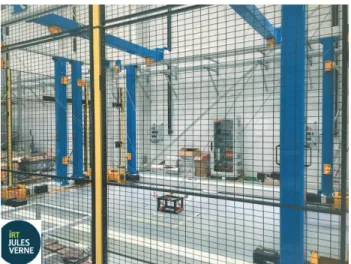
Fig. 1: CAROCA prototype: a reconfigurable CDPR (Courtesy of IRT Jules Verne, Nantes)
a suspended configuration of the reconfigurable CAROCA prototype, shown in Fig. 1, is studied. First, the manipulator under study is described. Then, its elasto-geometrical model is written while considering cable mass and elasticity in order to express the static deflection of the MP subjected to an external load. An exhaustive list of geometrical and mechanical uncertainties is given. Finally, the sensitivity of the MP static deflection to these uncertainties is analyzed.
2 Parametrization of the CAROCA prototype
The reconfigurable CAROCA prototype illustrated in Fig. 1 was developed at IRT Jules Verne for industrial operations in cluttered environment such as painting and sandblasting large structures [3, 4]. This prototype is reconfigurable because its pulleys can be displaced in a discrete manner on its frame. The size of the latter is 7 m long, 4 m wide and 3 m high. The rotation-resistant steel cables Carl Stahl Technocables Ref 1692 of the CAROCA prototype are 4 mm diameter. Each cable consists of 18 strands twisted around a steel core. Each strand is made up of 7 steel
wires. The cable breaking force is 10.29 kN. ρ denotes the cable linear mass and
Ethe cable modulus of elasticity.
B
iA
iz
py
px
px
by
bz
b bp
bb
i pa
i bl
i Oz
ix
iy
iP
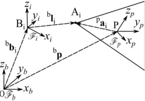
Fig. 2: The ith closed-loop of a CDPR
As shown in Fig. 2, the Cartesian coordinate vectors of anchor points Ai and
exit points Biare denoted aiand bi. Vector p represents the Cartesian coordinates
of the MP geometric center, P, expressed inFb= {O, xb, yb, zb}. The Cartesian
coordinates of Ai(Bi, resp.) expressed in the MP frameFp= {P, xp, yp, zp} (in the
base frameFb, resp.) are given in Tab. 1. The cable frameFi= {Bi, xi, yi, zi} is
associated to the ith cable, where axes ziand zbare parallel.
Table 1: Cartesian coordinates of anchor points Ai(exit points Bi, resp.) expressed
inFp(inFb, resp.) x (m) y (m) z (m) x (m) y (m) z (m) B1 -3.5 2 3.5 A1 0.2 0.15 0.125 B2 3.5 2 3.5 A2 -0.2 0.15 -0.125 B3 -3.5 2 3.5 A3 -0.2 -0.15 -0.125 B4 3.5 2 3.5 A4 0.2 -0.15 0.125 B5 -3.5 -2 3.5 A5 -0.2 0.15 0.125 B6 3.5 -2 3.5 A6 0.2 0.15 -0.125 B7 -3.5 -2 3.5 A7 0.2 -0.15 -0.125 B8 3.5 -2 3.5 A8 -0.2 -0.15 0.125
3 Elasto-geometric modeling
In this section, both sag-introduced and axial stiffness of cables are considered in the elasto-geometrical modeling of CDPR. The inverse elasto-geometrical model and the direct elasto-geometrical model of CDPR are presented. Then, the variations in static deflection due to external loading is defined as a sensitivity index.
3.1 Inverse Elasto-Geometric Modeling (IEGM)
The IEGM of a CDPR aims at calculating the unstrained cable length for a given pose of its MP. If both cable mass and elasticity are considered, the inverse kinematics of the CDPR and its static equilibrium equations should be solved simultaneously. The
IEGM is based on geometric closed loop equations, cable sagging relationships and static equilibrium equations.
The geometric closed-loop equations take the form:
bp =bb
i+bli−bRppai, (1)
wherebR
pis the rotation matrix fromFbtoFpand liis the cable length vector.
The cable sagging relationships between the forcesifi= [ifxi, 0,ifzi] applied at the
end point Aiof the ith cable and the coordinates vectoriai= [ixAi, 0,izAi] of the same
point resulting from the sagging cable model [9] are expressed inFias follows:
ix Ai= if xiLusi ES + |if xi| ρ g [sinh −1(ifzi fCi xi ) − sinh−1( if zi− ρgLusi if xi )], (2a) iz Ai= if xiLusi ES − ρ gL2usi 2ES + 1 ρ g[ q if xi2+ifzi2− q if xi2+ (ifzi− ρgLusi)2], (2b)
where Lusiis the unstrained length of ith cable, g is the acceleration due to gravity, S
is the cross sectional area of the cables.
The static equilibrium equations of the MP are expressed as:
Wt + wex= 0, (3)
where W is the wrench matrix, wexis the external wrench vector and t is the
8-dimensional cable tension vector. Those tensions are computed based on the tension distribution algorithm described in [10].
3.2 Direct elasto-geometrical model (DEGM)
The direct elasto-geometrical model (DEGM) aims to determine the pose of the mobile platform for a given set of unstrained cable lengths. The constraints of the DEGM are the same as the IEGM, i.e, Eq. (1) to Eq. (3). If the effect of cable weight on the static cable profile is non-negligible, the direct kinematic model of CDPRs will be coupled with the static equilibrium of the MP. For a 6 DOFs CDPR with 8 driving cables, there are 22 equations and 22 unknowns. In this paper, the non-linear Matlab function ``lsqnonlin´´ is used to solve the DEGM.
3.3 Static deflection
If the compliant displacement of the MP under the external load is small, the static deflection of the MP can be calculated by its static Cartesian stiffness matrix [11]. However, once the cable mass is considered, the sag-introduced stiffness should be taken into account. Here, the small compliant displacement assumption is no longer valid, mainly for heavy or/and long cables with light mobile platform. Consequently, the static deflection can not be calculated through the Cartesian stiffness matrix. In this paper, the IEGM and DEGM are used to define and calculate the static deflection of the MP under an external load. The CDPR stiffness is characterized by the static deflection of the MP. Note that only the positioning static deflection of the MP is considered in order to avoid the homogenization problem [12].
As this paper deals with the sensitivity of the CDPR accuracy to all geometrical and mechanical errors, the elastic deformations of the CDPR is involved. This problem is solved by deriving the static deflection of the CDPR obtained by the subtraction of the poses calculated with and without an external payload. For a
desired pose of the MP, the IEGM gives a set of unstrained cable lengths Lus. This
set is used by the DEGM to calculate first, the pose of the MP under its own weight. Then, the pose of the MP is calculated when an external load (mass addition) is applied. Therefore, the static deflection of the MP is expressed as:
dpj,k= pj,k− pj,1, (4)
where pj,1is the pose of the MP considering only its own weight for the jth pose
configuration and pj,kis the pose of the MP for the set of the jthpose and kthload
configuration.
4 Error modeling
This section aims to define the error model of the elasto-geometrical CDPR model. Two types of errors are considered: geometrical errors and mechanical errors.
4.1 Geometrical errors
The geometrical errors of the CDPR are described by δ bi, the variation in vector bi,
δ ai, the variation in vector ai, and δ g, the uncertainty vector of the gravity center
position; So, 51 uncertainties. The geometric errors can be divided into base frame geometrical errors and MP geometrical errors and mainly due to manufacturing errors.
4.1.1 Base frame geometrical errors
The base frame geometrical errors are described by vectors δ bi, (i=1..8). As the point
Biis considered as part of its correspondent pulley, it is influenced by the elasticity
of the pulley mounting and its assembly tolerance. biis particularly influenced by
pulleys tolerances and reconfigurability impact. 4.1.2 Moving-platform geometrical errors
The MP geometrical errors are described by vectors δ ai, (i=1..8), and δ g. The gravity
center of the MP is often supposed to coincide with its geometrical center P. This hypothesis means that the moments generated by an inaccurate knowledge of the gravity center position or by its potential displacement are neglected. The Cartesian
coordinate vector of the geometric center G does not change in frameFp, but strongly
depends on the real coordinates of exit points Aithat are related to uncertainties in
mechanical welding of the hooks and in MP assembly.
4.2 Mechanical errors
The mechanical errors of the CDPR are described by the uncertainty in the MP mass (δ m) and the uncertainty on the cables mechanical parameters (δ ρ and δ E).
Besides, uncertainties in the cables tension δ t affect the error model. As a result, 11 mechanical error sources are taken into account.
4.2.1 End-effector mass
As the MP is a mechanically welded structure, there may be some differences between the MP mass and inertia matrix given by the CAD software and the real ones. The MP mass and inertia may also vary in operation In this paper, MP mass uncertainty δ m is about ± 10% the nominal mass.
4.2.2 Cables parameters
Linear mass:The linear mass ρ of CAROCA cables is equal to 0.1015 kg/m. The
uncertainty of this parameter can be calculated from the measurement procedure as:
δ ρ =mcδ L + L δ mc
L2 , where mcis the measured cable mass for a cable length L. δ L
and δ mcare respectively the measurement errors of the cable length and mass.
Modulus of elasticity:This paper uses experimental hysteresis loop to discuss the
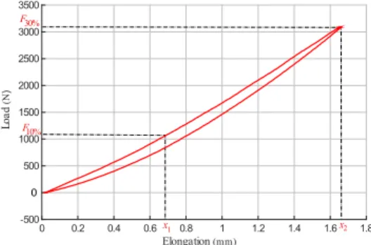
modulus of elasticity uncertainty. Figure 3 shows the measured hysteresis loop of the 4 mm cable where the unloading path does not correspond to the loading path. The area in the center of the hysteresis loop is the energy dissipated due to internal friction in the cable. It depicts a non-linear correlation in the lower area between load and elongation. Elongation (mm) 0 0.2 0.4 0.6 0.8 1 1.2 1.4 1.6 1.8 L o a d (N ) -500 500 1000 1500 2000 2500 3000 3500 0 x 1 x2 F 30% F 10%
Fig. 3: Load-elongation diagram of a steel wire cable measured in steady state conditions at the rate of 0.05 mm/s
Based on experimental data presented in Fig. 3, Table 2 presents the modulus of elasticity of a steel wire cable for different operating margins, when the cable is in loading or unloading phase. This modulus is calculated as follows:
Ep−q= Lc
Fq%− Fp%
S(xq− xp)
, (5)
where S is the metallic cross-sectional area, i.e. the value obtained from the sum of the metallic cross-sectional areas of the individual wires in the rope based on their
nominal diameters. xpand xqare the elongations at forces equivalent to p% and q%
(Fp%and Fq%), respectively, of the nominal breaking force of the cable measured
during the loading path (Fig. 3). Lcis the measured initial cable length.
Table 2: Modulus of elasticity while loading or unloading phase
Modulus of elasticity (GPa) E1−5E5−10E5−20 E5−30E10−15E10−20E10−30 E20−30
Loading 72.5 83.2 92.7 97.2 94.8 98.3 102.2 104.9 Unloading 59.1 82.3 96.2 106.5 100.1 105.1 115 126.8
For a given range of loads (Tab. 2), the uncertainty on the modulus of elasticity depends only on the corresponding elongations and tensions measurements. In this case, the absolute uncertainty associated with applied force and resulting elongation measurements from the test bench outputs is estimated to be ± 1 N and ± 0.03 mm, respectively; so, an uncertainty of ± 2 GPa can be applied to the calculation of the modulus of elasticity.
According to the International Standard ISO 12076, the modulus of elasticity of a
steel wire cable is E10−30. However, the CDPR cables do not work always between
F10%and F30%in real life and the cables can be in loading or unloading phase. The
mechanical behavior of cables depends on MP dynamics, which affects the variations in cable elongations and tensions. From Table 2, it is apparent that the elasticity moduli of cables change with the operating point changes. For the same applied force, the modulus of elasticity for loaded and unloaded cables are not the same. While the range of the MP loading is unknown, a large range of uncertainties on the modulus of elasticity should be defined as a function of the cable tensions.
4.2.3 Tension distribution
Two cases of uncertainties of force determination can be defined depending on the control scheme:
The first case is when the control scheme gives a tension set-point to the actuators resulting from the force distribution algorithm. If there is no feedback about the tensions measures, the range of uncertainty is relatively high. Generally, the effort of compensation does not consider dry and viscous friction in cable drum and pulleys. This non-compensation leads to static errors and delay [13] that degrade the CDPR control performance. That leads to a large range of uncertainties in tensions. As the benefit of tension distribution algorithm used is less important in case of a suspended configuration of CDPR than the fully-constrained one [14], a range of ± 15 N is defined.
The second case is when the tensions are measured. If measurement signals are very noisy, amplitude peaks of the correction signal may lead to a failure of the force distribution. Such a failure may also occur due to variations in the MP and pulleys parameters. Here, the deviation is defined based on the measurement tool precision. However, it remains lower than the deviation of the first case by at least 50%.
5 Sensitivity Analysis
Due to the non-linearities of the elasto-geometrical model, explicit sensitivity matrix and coefficients [15, 16] cannot be computed. Therefore, the sensitivity of the elasto-geometrical model of the CDPR to elasto-geometrical and mechanical errors is evaluated statistically. Here, MATLAB has been coupled with modeFRONTIER, a process integration and optimization software platform [17] for the analysis.
The RMS (Root Mean Square) of the static deflection of CAROCA MP is studied. The nominal mass of the MP and the additional mass are equal to 180 kg and 50 kg, respectively.
5.1 Influence of mechanical errors
In this section, all the uncertain parameters of the elasto-geometrical CAROCA model are defined with uniformly distributed deviations. The uncertainty range and discretization step are given in Tab. 3. In this basis, 2000 SOBOL quai-randm observations are created.
Table 3: Uncertainties and steps used to design the error model
Parameter m(kg) ρ (kg/m) E (GPa) ai(m) bi(m) δ ti(N)
Uncertainty range ± 18 ± 0.01015 ± 18 ± 0.015 ± 0.03 ± 15 Step 0.05 3*10−5 0.05 0.0006 0.0012 0.1
In this configuration, the operating point of the MP is supposed to be unknown. A large variation range of the modulus of elasticity is considered. The additional mass corresponds to a variation in cable tensions from 574 N to 730 N, which corresponds to a modulus of elasticity of 84.64 GPa. Thus, while the operating point of the MP is unknown, an uncertainty of ± 18 GPa is defined with regard to the measured modulus of elasticity E= 102 GPa.
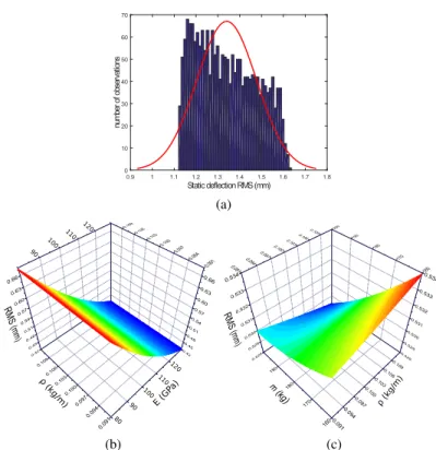
Figure 4a displays the distribution fitting of the static deflection RMS. It shows
that the RMS distribution follows a quasi-uniform law whose mean µ1is equal to
1.34 mm. The RMS of the static deflection of the MP is bounded between a minimum
value RMSminequal to 1.12 mm and a maximum value RMSmaxequal to 1.63 mm;
a variation of 0.51 mm under all uncertainties, which presents 38% of the nominal value of the static deflection.
Figure 4b depicts the RMS of the MP static deflection as a function of varia-tions in E and ρ simultaneously, whose values vary respectively from 0.09135 to 0.11165 kg/m and from 84.2 to 120.2 GPa. The static deflection is very sensitive to cables mechanical behavior. The RMS varies from 0.42 mm to 0.67 mm due to the uncertainties of these two parameters only. As a matter of fact, the higher the cable modulus of elasticity, the smaller the RMS of the MP static deflection. Conversely, the smaller the linear mass of the cable, the smaller the RMS of the MP static deflection. Accordingly, the higher the sag-introduced stiffness, the higher the MP static deflection. Besides, the higher the axial stiffness of the cable, the lower the MP static deflection.
Static deflection RMS (mm) 0.9 1 1.1 1.2 1.3 1.4 1.5 1.6 1.7 1.8 nu m be r of o bs er va tio ns 0 10 20 30 40 50 60 70 (a) 100 110 120 90 80 E (GP a) 100 110 120 90 (kg/m) (b) ρ ( kg/m) (c)
Fig. 4: (a) Distribution of the RMS of the MP static deflection (b) Evolution of the RMS under a simultaneous variations of E and ρ (c) Evolution of the RMS under a simultaneous variations of m and ρ
Figure 4c illustrates the RMS of the MP static deflection as a function of variations in ρ and m, whose value varies from 162 kg to 198 kg. The RMS varies from 0.52 mm to 0.53 mm due to the uncertainties of these two parameters only. The MP mass affects the mechanical behavior of cables: the heavier the MP, the larger the axial stiffness, the smaller the MP static deflection. Therefore, a fine identification of m and ρ is very important to establish a good CDPR model.
Comparing to the results plotted in Fig. 4b, it is clear that E affects the RMS of the MP static deflection more than m and ρ. As a conclusion, the integration of cables hysteresis effects on the error model is necessary and improves force algorithms and the identification of the robot geometrical parameters [16].
5.2 Influence of geometrical errors
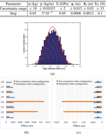
In this section, the cable tension set-points during MP operation are supposed to be known; so, the modulus of elasticity can be calculated around the operating point and the confidence interval is reduced to ± 2 GPa. The uncertainty range and the discretization step are provided in Tab. 4.
Table 4: Uncertainties and steps used to design the error model Parameter m(kg) ρ (kg/m) E (GPa) ai(m) bi(m) δ ti(N) Uncertainty range ± 18 ± 0.01015 ± 2 ± 0.015 ± 0.03 ± 15 Step 0.05 3*10−5 0.05 0.0006 0.0012 0.1 Static deflection RMS (mm) 1.26 1.28 1.3 1.32 1.34 1.36 1.38 1.4 nu m be r of o bs er va tio ns 0 20 40 60 80 100 120 (a) 0 0,002 0,004 0,006 0,008 0,01 0,012 A1 A2 A3 A4 A5 A6 A7 A8 Effect size
Non-symmetric robot configuration Symmetric robot configuration
(b) -0,025 -0,02 -0,015 -0,01 -0,005 0 B1 B2 B3 B4 B5 B6 B7 B8 Effect size Non-symmetric robot configuration Symmetric robot configuration
(c)
Fig. 5: (a) Distribution of the RMS of the MP static deflection (b) Effect of
uncer-tainties in ai(c) Effect of uncertainties in bi
Figure 5a displays the distribution fitting of the MP static deflection RMS. It
shows that the RMS distribution follows a normal law whose mean µ2is equal
to 1.32 mm and its standard deviation σ2is equal to 0.01 mm. This deviation is
relatively small, which allows to say that the calibration through static deflection is not obvious. The RMS of the static deflection of the MP is bounded between a
minimum value RMSminequal to 1.28 mm and a maximum value RMSmaxequal to
1.39 mm; a variation of 0.11 mm under all uncertainties. The modulus of elasticity affects the static compliant of the MP, which imposes to always consider E error while designing a CDPR model.
The bar charts plotted in Fig. 5b and Fig. 5c present, respectively, the effects of
the uncertainties in aiand bi, (i=1..8), to the static deflection of the CAROCA for
symmetric (0 m, 0 m, 1.75 m) and non-symmetric (3.2 m, 1.7 m, 3 m) robot config-urations. These effects are determined based on t-student index of each uncertain
parameter. This index is a statistical tool that can estimate the relationships between outputs and uncertain inputs. The t-Student test compares the difference between the means of two samples of designs taken randomly in the design space:
• M+is the mean of the n+values for an objective S in the upper part of domain of
the input variable,
• M−is the mean of the n−values for an objective S in the lower part of domain of
the input variable.
The t-Student is defined as t =s|M−− M+|
Vg2 n− +V 2 g n+
, where Vgis the general variance [18].
When the MP is in a symmetric configuration, all attachment points have nearly
the same effect size. However, when it is located close to points B2and B4, the effect
size of their uncertainties becomes high. Moreover, the effect of the corresponding
mobile points (A2 and A4) increases. It means that the closer the MP to a given
point, the higher the effect of the variations in the Cartesian coordinates of the corresponding exit point of the MP onto its static deflection. That can be explained by the fact that when some cables are longer than others and become slack for a non-symmetric position, the sag effect increases. Consequently, a good identification of geometrical parameters is highly required. In order to minimize these uncertainties, a good calibration leads to a better error model.
6 Conclusion
This paper dealt with the sensitivity analysis of the elasto-geometrical model of CDPRs to mechanical and geometrical uncertainties. The CAROCA prototype was used as a case of study. The validity and identifiability of the proposed model are verified for the purpose of CDPR model-based control. That revealed the impor-tance of integrating cables hysteresis effect into the error modeling to enhance the knowledge about cables mechanical behavior, especially when there is no feedback about tension measurement. It appears that the effect of geometrical errors onto the static deflection of the moving-platform is significant too. Some calibration [19, 20] and self-calibration [21, 22] approaches were proposed to enhance the CDPR per-formances. More efficient strategies for CDPR calibration will be performed while considering more sources of errors in a future work.
References
1. Merlet, J. P. (2010). MARIONET, a family of modular wire-driven parallel robots. In Advances in Robot Kinematics: Motion in Man and Machine (pp. 53-61). Springer Netherlands. 2. Dallej, T., Gouttefarde, M., Andreff, N., Michelin, M., Martinet, P. (2011, September). Towards
vision-based control of cable-driven parallel robots. In Intelligent Robots and Systems (IROS), 2011 IEEE/RSJ International Conference on (pp. 2855-2860). IEEE.
3. Gagliardini, L., Caro, S., Gouttefarde, M., Girin, A. (2015, May). A reconfiguration strategy for reconfigurable cable-driven parallel robots. In Robotics and Automation (ICRA), 2015 IEEE International Conference on (pp. 1613-1620). IEEE.
4. Gagliardini, L., Caro, S., Gouttefarde, M., Girin, A. (2016). Discrete reconfiguration planning for cable-driven parallel robots. Mechanism and Machine Theory, 100, 313-337.
5. Jamshidifar, H., Fidan, B., Gungor, G., Khajepour, A. (2015). Adaptive Vibration Control of a Flexible Cable Driven Parallel Robot. IFAC-PapersOnLine, 48(3), 1302-1307.
6. Fang, S., Franitza, D., Torlo, M., Bekes, F., Hiller, M. (2004). Motion control of a tendon-based parallel manipulator using optimal tension distribution. IEEE/ASME Transactions On Mechatronics, 9(3), 561-568.
7. Zi, B., Duan, B. Y., Du, J. L., Bao, H. (2008). Dynamic modeling and active control of a cable-suspended parallel robot. Mechatronics, 18(1), 1-12.
8. Pott, A., Mtherich, H., Kraus, W., Schmidt, V., Miermeister, P., Verl, A. (2013). IPAnema: a family of cable-driven parallel robots for industrial applications. In Cable-Driven Parallel Robots (pp. 119-134). Springer Berlin Heidelberg.
9. Irvine, H. M. (1992). Cable structures. Dover Publications.
10. Mikelsons, L., Bruckmann, T., Hiller, M., Schramm, D. (2008, May). A real-time capable force calculation algorithm for redundant tendon-based parallel manipulators. In Robotics and Automation, 2008. ICRA 2008. IEEE International Conference on (pp. 3869-3874). IEEE. 11. Carbone, G. (2011). Stiffness analysis and experimental validation of robotic systems. Frontiers
of Mechanical Engineering, 6(2), 182-196.
12. Nguyen, D. Q., Gouttefarde, M. (2014). Stiffness Matrix of 6-DOF Cable-Driven Parallel Robots and Its Homogenization. In Advances in Robot Kinematics (pp. 181-191). Springer International Publishing.
13. De Wit, C. C., Seront, V. (1990, May). Robust adaptive friction compensation. In Robotics and Automation, 1990. Proceedings., 1990 IEEE International Conference on (pp. 1383-1388). IEEE.
14. Lamaury, J. (2013). Contribution a la commande des robots parallles a cbles redondance d’actionnement (Doctoral dissertation, Universit Montpellier II-Sciences et Techniques du Languedoc).
15. Zi, B., Ding, H., Wu, X., Kecskemthy, A. (2014). Error modeling and sensitivity analysis of a hybrid-driven based cable parallel manipulator. Precision Engineering, 38(1), 197-211. 16. Miermeister, P., Kraus, W., Lan, T., Pott, A. (2015). An elastic cable model for cable-driven
parallel robots including hysteresis effects. In Cable-Driven Parallel Robots (pp. 17-28). Springer International Publishing.
17. modeFRONTIER, www.esteco.com
18. Courteille, E., Deblaise, D., Maurine, P. (2009, October). Design optimization of a delta-like parallel robot through global stiffness performance evaluation. In Intelligent Robots and Systems, 2009. IROS 2009. IEEE/RSJ International Conference on (pp. 5159-5166). IEEE. 19. dit Sandretto, J. A., Trombettoni, G., Daney, D., Chabert, G. (2014). Certified calibration of a
cable-driven robot using interval contractor programming. In Computational Kinematics (pp. 209-217). Springer Netherlands.
20. Joshi, S. A., Surianarayan, A. (2003). Calibration of a 6-DOF cable robot using two incli-nometers. Performance metrics for intelligent systems, 3660-3665.
21. Miermeister, P., Pott, A., Verl, A. (2012, May). Auto-calibration method for overconstrained cable-driven parallel robots. In Robotics; Proceedings of ROBOTIK 2012; 7th German Con-ference on (pp. 1-6). VDE.
22. Borgstrom, P. H., Jordan, B. L., Borgstrom, B. J., Stealey, M. J., Sukhatme, G. S., Batalin, M. A., Kaiser, W. J. (2009). Nims-pl: A cable-driven robot with self-calibration capabilities. IEEE Transactions on Robotics, 25(5), 1005-1015.