Remerciement
En premier lieu, je souhaite remercier le ministère Algérien de l’enseignement supérieur et de la recherche scientifique d’avoir financé ma thèse durant ces années et de m’avoir permis de perfectionner mes connaissances au cours de cette thèse à l’IRIT.
J’adresse mes remerciements à mon encadrant Martin Strecker, maître de conférence à l’Université Paul Sabatier (Toulouse) pour le temps qu’il m’a accordé mais aussi pour tout ce qu’il m’a appris et permis d’apprendre. Je remercie aussi mon directeur de thèse, Ralph Matthes, chargé de recherche CNRS à l’IRIT, pour ses précieux conseils et sa bonne humeur.
Je souhaite remercier particulièrement Mohamed Mezghiche, professeur à l’université M’hamed Bougara de Boumerdès (Algérie), d’avoir cru en moi depuis le début et de m’avoir toujours encouragée. Je suis ravie d’intégrer son équipe l’année prochaine et espère être à la hauteur de ses attentes.
Un grand merci aux autres membres du jury d’avoir accepter et pris le temps d’évaluer ma thèse.
Je remercie chaleureusement l’ensemble de l’équipe ACADIE dont les membre m’ont accueillit parmi eux pendant quatre années. C’était très agréable de les rencontrer tout les jours, et de travailler parmi eux, en particulier: Mamoun, Jean-Paul, Bertrand, Math-ieu, Manuel, Jean Baptiste, Yamine... etc. Je les remercie pour leurs gentillesse et leurs encouragements.
Je tiens également à remercier les membres avec qui j’ai partagé mon bureau pendant ces années : Nadezhda, Iulia et Elie. Merci pour tous les coup de gueule et les fous rires, je vous souhaite le meilleur.
Lorsque je suis arrivée à Toulouse, j’étais loin de ma famille, mais heureusement petit à petit je me suis reconstruit une petite famille ici. Ces personnes, je les garderai toujours
dans mon coeur. Je leur témoigne toute ma gratitude pour avoir été là pour moi dans les bons comme dans les mauvais moments : Mounira, Faten, Fatiha, Akila, Hajer, Anis, Rym et Jamel; sans oublier mes deux bouts de chou: Chahd et Rayane.
Un remerciement chaleureux à mes amis en France et en Algérie en particulier mes adorées: Sarah, Nabila et Ludivine.
Pour leur soutien indéfectible, je remercie toute ma famille, en particulier ma soeur Amina et mon frère Mehdi. Bien sûr, je remercie grandement mes chers parents sans qui je n’en serais pas là aujourd’hui. Merci pour leurs sacrifices pour assurer mon éducation, j’espère les rendre fiers.
Enfin, je remercie sincèrement mon fiancé Mebarek pour sa présence même dans les moments les plus difficiles et pour son soutien sans failles.
Selma Djeddai
Association d’environnements de vérification formelle et de l’Ingénierie Dirigée par les Modèles
Directeur de thèse : Ralph Matthes, CNRS Co-directeur de thèse : Martin Strecker, CNRS
Résumé
Les méthodes formelles (comme les prouveurs interactifs) sont de plus en plus utilisées dans la vérification de logiciels (en particulier les logiciels critiques). Elles peuvent compter sur leurs bases formelles solides ainsi que sur leurs sémantiques précises. Cependant, elles utilisent des notations complexes qui sont souvent difficiles à comprendre pour un public non averti. Ce problème se pose particulièrement lors de collaborations entre des experts du domaine industriel et des professionnels de la preuve interactive. En effet, les ex-perts du domaine industriel ont parfois du mal à voir précisément comment leurs systèmes sont représentés dans les assistants de preuves. D’un autre côté, ces experts sont souvent habitués à interagir avec les outils et formalismes que propose l’Ingénierie Dirigée par les Modèles comme les diagrammes de classes. Ces diagrammes utilisent des notations intu-itives mais souffrent d’un manque de bases formelles. Aussi, ils ne permettent aucunement d’effectuer des vérifications sur les systèmes.
Dans cette thèse, nous proposons de faire interagir les deux domaines complémentaires que sont les méthodes formelles et l’ingénierie dirigée par les modèles. Nous proposons une approche permettant de traduire des types de données fonctionnels (utilisés dans les prouveurs interactifs comme Coq ou Isabelle) en diagrammes de classes et vice-versa. Afin d’atteindre ce but, nous utilisons une méthode de transformation dirigée par les modèles. Cette dernière consiste à définir des règles de transformation sur les éléments d’un méta-modèle source vers les éléments d’un méta-méta-modèle cible. Dans ce cas, tout méta-modèle source (conforme au méta-modèle source) donne automatiquement un modèle cible (conforme au méta-modèle cible) après application de la transformation.
Par conséquent, nous définissons dans cette thèse chacun des méta-modèles source et cible pour les types de données fonctionnels ainsi que pour les diagrammes de classes. Nous décrivons aussi les règles de transformation dans les deux sens de la transformation. Nous illustrons notre approche avec deux études de cas et combinons nos résultats avec la génération d’éditeurs graphiques ou textuels à partir de diagrammes de classes (en utilisant les outils GMF et Xtext). La première étude de cas porte sur les diagrammes de décision binaires, tandis que la seconde décrit la définition d’un langage spécifique à un domaine: Safety Critical Java.
Institut de Recherche en Informatique de Toulouse - UMR 5505 Université Paul Sabatier, 118 route de Narbonne, 31062 TOULOUSE cedex 4
Selma Djeddai
Combining Formal Verification Environments and Model-Driven Engineering
Thesis Advisor: Ralph Matthes, C.N.R.S. Thesis Co-advisor: Martin Strecker, C.N.R.S.
Abstract
Formal methods (such as interactive provers) are increasingly used in software verification especially for critical software. This is so because they rely on their strong formal basis and precise semantics. However, they use complex notations that are often difficult to understand for unaccustomed users. This becomes a problem when a collaboration is needed between interactive proof professionals on the one hand and domain experts on the other hand. In fact, the latter may have trouble to see precisely how their system specifications are represented in proof assistants, because they are often used to interact with specific Model Driven Engineering tools and formalisms (such as class diagrams). These latter offer a more attractive syntax and use intuitive notations. However, they suffer from a lack of formal foundations and do not allow to perform verification on systems.
In this thesis, we are interested in combining these two complementary domains that are formal methods and Model Driven Engineering. We propose an approach allowing to translate functional data types (used in interactive provers like Coq or Isabelle) into class diagrams and vice versa. To achieve this goal, we use a model-driven transforma-tion method. This method consists in defining transformatransforma-tion rules from the elements of a source meta-model into those of a target meta-model. Consequently, after processing the transformation, every source model (which conforms to the source meta-model) gives automatically a target model (which conforms to the target meta-model).
Therefore, we define in this thesis each of the source and target meta-models for each of the functional data types and the class diagrams. We also describe the transformation rules in both directions of the transformation. We illustrate our approach with two case studies and combine our results with the generation of graphical or textual editors out of class diagrams (using the tools Xtext and GMF). The first case study deals with Binary Decision Diagrams, while the second describes the definition of a domain specific language: Safety Critical Java.
Institut de Recherche en Informatique de Toulouse - UMR 5505 Université Paul Sabatier, 118 route de Narbonne, 31062 TOULOUSE cedex 4
CONTENTS
Contents
List of Figures xv
List of Tables xvii
Introduction 1
1 Scientific Context and Related Work 7
1.1 Introduction. . . 7
1.2 Model Driven Engineering . . . 7
1.2.1 Model and Meta-Model . . . 8
1.2.2 Domain Specific Languages (DSL) . . . 8
1.2.3 Model Driven Architecture . . . 8
1.2.4 The Four-Layer MOF Meta-modeling Architecture . . . 9
1.3 Model Transformation . . . 9
1.3.1 Classification of Model Transformation Approaches . . . 11
1.3.2 Model Transformation Tools . . . 13
1.3.2.1 The Attributed Graph Grammar (AGG) . . . 13
1.3.2.2 AToM3 . . . 14
1.3.2.3 MOFLON . . . 14
1.3.2.4 The ATLAS Transformation Language . . . 15
1.3.2.5 Kermeta . . . 16
1.3.2.6 Synthesis . . . 16
1.4 Related Work . . . 17
1.4.1 Formal Frameworks and Model Driven Engineering . . . 17
1.4.1.1 Coq4MDE . . . 18
1.4.1.2 A Formal Proof Environment for UML/OCL . . . 18
1.4.2 From Class Diagrams to Formal Languages and Back Again . . . 19
1.4.2.1 B To UML and Back Again. . . 19
1.4.2.2 UML To Alloy and Back Again. . . 20
1.4.2.3 Focal To UML . . . 21
CONTENTS
I EMF/Functional Data structures 23
2 Eclipse Modeling Framework 25
2.1 Introduction. . . 25
2.2 Overview of the Eclipse Modeling Framework . . . 25
2.3 Defining EMF Models . . . 26
2.3.1 Packages . . . 26 2.3.2 Factories . . . 26 2.3.3 Classifiers . . . 26 2.3.4 Classes . . . 27 2.3.4.1 Generalization Link . . . 27 2.3.5 Data Types . . . 27 2.3.6 Enumerated Types . . . 27 2.3.7 Structural Features. . . 27 2.3.7.1 Attributes . . . 29 2.3.7.2 References . . . 29 2.3.8 Behavioral Features . . . 29 2.3.8.1 Operations . . . 29
2.3.9 Generics Representation in Ecore . . . 29
2.4 Eclipse Modeling Framework and UML . . . 30
2.5 Features of EMF Used in this Thesis . . . 30
2.5.1 Textual Representation for Meta-models . . . 31
2.6 Eclipse Modeling Project . . . 33
2.6.1 Graphical Modeling Framework . . . 33
2.6.1.1 GMF Architecture . . . 34 2.6.1.2 Using GMF. . . 34 2.6.2 Xtext . . . 35 2.7 Summary . . . 36 3 Formal Framework 37 3.1 Introduction. . . 37 3.2 Functional Programming. . . 38 3.2.1 Interactive Provers . . . 39
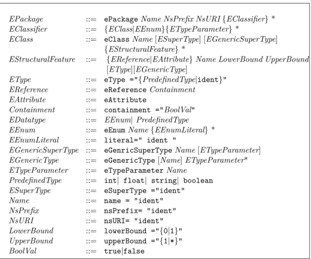
3.3 Abstract Syntax of ML Languages . . . 39
3.3.1 Data Types . . . 39
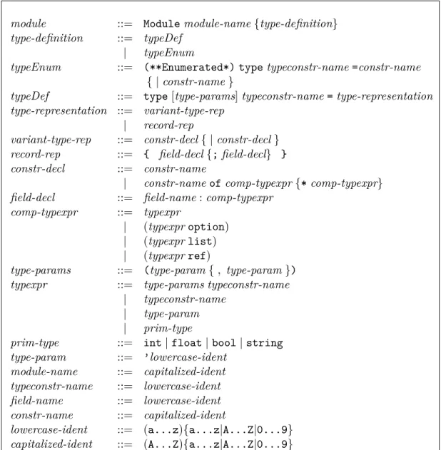
3.3.1.1 User Defined Data Types . . . 39
3.3.1.2 Predefined Data Types . . . 40
3.3.2 Functions . . . 42
3.4 Features of Functional Programming Used in this Thesis . . . 43
3.4.1 Part of Caml Grammar Used in this Thesis . . . 43
3.4.2 Proposed Extension for Accessor Functions . . . 45 xi
CONTENTS
3.4.3 Example of a Data Type Definition. . . 45
3.4.4 Part of Isabelle Grammar Used in this Thesis . . . 46
3.5 Meta-model of the Formal Framework . . . 46
3.6 Summary . . . 48
II From Functional Models to Meta-models and Back Again 49 4 Functional Models to EMF 51 4.1 Introduction. . . 51
4.2 Well-formedness Constraints for Input Data Types . . . 51
4.3 Transformation Rules Representation . . . 52
4.4 Rule ModuleToEPackage. . . 53 4.5 Rule DatatypeToEClass . . . 54 4.6 Rule DatatypeToEEnum . . . 54 4.7 Rule DatatypeToEClasses . . . 55 4.8 Rule RecordToEClass . . . 56 4.9 Rule PrimitiveTypeToEAttribute . . . 56 4.10 Rule TypeToEReference . . . 57 4.11 Rule OptionToMultiplicity . . . 58 4.12 Rule ListToMultiplicity . . . 59 4.13 Rule RefToEReference . . . 59
4.14 Transforming Accessors to Structural Features Names . . . 60
4.15 Transforming Generics . . . 61
4.16 Summary . . . 63
5 EMF to Functional Models 65 5.1 Introduction. . . 65
5.2 Well-formedness Constraints for Input Meta Models . . . 65
5.3 Representation of Transformation Rules . . . 66
5.4 Rule EPackageToModule. . . 67 5.5 Rule EEnumToDatatype . . . 67 5.6 Rule EClassToDatatype . . . 68 5.7 Rule EClassInheritanceToDatatype . . . 68 5.7.1 Rule EClassToConstructor. . . 69 5.7.2 Rule ETypeParameterToTypeParameter . . . 70 5.8 Rule EAttributeToType . . . 71 5.8.1 Rule EAttributeToTypeParameter . . . 71 5.9 Rule EReferenceToType . . . 72 5.9.1 Rule ContainmentToRef . . . 73 5.9.2 Rule EReferenceToParametrizedType . . . 73
CONTENTS
5.10 Rule MultiplicitiesToTypeOptions . . . 74
5.11 Summary . . . 75
III Case Studies 77 6 Binary Decision Diagrams 79 6.1 Introduction. . . 79
6.2 Binary Decision Diagrams . . . 79
6.3 Verified BDD Construction . . . 80
6.4 Presentation of the Case Study . . . 80
6.5 Generating Ecore Diagrams from Data Types . . . 82
6.5.1 Applying the Transformation on the Formula Type Definition . . . . 82
6.5.2 Applying the Transformation on the BDD Type Definition . . . 83
6.6 Using Xtext Facilities to define a DSL Textual Editor: Application to the Boolean Formula Example . . . 84
6.7 Using GMF Facilities to define a DSL Graphical Editor: Application to the BDD Example . . . 85
6.8 A Complete Execution of the Case Study . . . 86
6.9 Summary . . . 87
7 Safety Critical Java 89 7.1 Introduction. . . 89
7.2 Defining Safety Critical Java . . . 89
7.2.1 Elements of the Language . . . 90
7.3 Presentation of the Case Study . . . 91
7.4 Generating an Ecore Diagram from Data Types . . . 91
7.5 Summary . . . 93
IV Conclusion 99
Conclusion and Perspectives 101
Bibliography 106
V Résumé de la thèse en Français 117
A Introduction 119
CONTENTS
B Contexte scientifique et travaux connexes 123
B.1 Contexte scientifique . . . 123
B.1.1 Ingénierie Dirigée par les Modèles (IDM) . . . 123
B.1.2 Transformation de Modèles . . . 124
B.2 Travaux connexes. . . 124
B.2.1 Méthodes formelles et IDM . . . 124
B.2.2 Transformations des diagrammes de classes aux langages formels et vice versa . . . 125
B.3 Résumé . . . 127
C Eclipse Modeling Framework 129 C.1 Eclipse Modeling Framework . . . 129
C.2 Sous-ensemble de EMF Utilisé dans cette thèse . . . 130
C.3 Résumé . . . 131
D Framework Formel 133 D.1 Programmation fonctionnelle . . . 133
D.1.1 Les prouveurs interactifs . . . 133
D.2 Sous-ensemble des langages fonctionnels utilisé dans cette thèse . . . 134
D.3 Résumé . . . 134
E Des modèles fonctionnels vers EMF 137 E.1 Conditions de bonne formation pour les types de données en entrée . . . 137
E.2 Règles de Transformations . . . 138
E.2.1 Règle DatatypeToEClasses . . . 138
E.2.2 Règle PrimitiveTypeToEAttribute . . . 139
E.2.3 Règle ListToMultiplicity . . . 139
E.3 Résumé . . . 140
F De EMF vers les modèles fonctionnels 141 F.1 Contraintes de bonne formation pour le méta-modèle source . . . 141
F.2 Règles de transformation. . . 142
F.2.1 Règle EEnumToDatatype . . . 142
F.2.2 Règle EAttributeToType . . . 142
F.3 Règle MultiplicitiesToTypeOptions . . . 144
F.4 Résumé . . . 144
G Diagrammes de décision binaires 145 G.1 Diagrammes de décision binaires . . . 145
G.2 Mise en place de l’étude de cas . . . 145
G.2.1 Présentation de l’étude de cas . . . 145
CONTENTS
G.3 Résumé . . . 148
H Safety Critical Java 149 H.1 Définition de Safety Chritical java . . . 149
H.2 Présentation de l’étude de cas . . . 149
H.3 Génération d’un diagramme Ecore à partir de types de données . . . 150
H.4 Résumé . . . 150
I Conclusion 151
LIST OF FIGURES
List of Figures
1 Overview of the Transformation Method . . . 2
2 Example of the Application of our Approach . . . 3
1.1 Meta-modeling Layers [18] . . . 10
1.2 Pattern for MDE Transformations [65] . . . 11
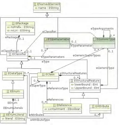
2.1 The Complete Ecore Meta-model [27] . . . 28
2.2 Simplified Subset of the Ecore Meta-model . . . 31
2.3 Grammar Allowing to Describe Ecore Models Textually . . . 32
2.4 Ecore Meta-model for an Arithmetic Expression. . . 33
2.5 Textual Representation of the Arithmetic Expression Model . . . 33
2.6 GMF Project Architecture . . . 35
2.7 GMF Workflow [51] . . . 36
3.1 Overview of the Transformation . . . 38
3.2 Syntax of Type Definitions in Caml [68] . . . 41
3.3 Caml Grammar of Data Types Used in this Thesis . . . 44
3.4 Syntax of Accessor Functions in Caml . . . 45
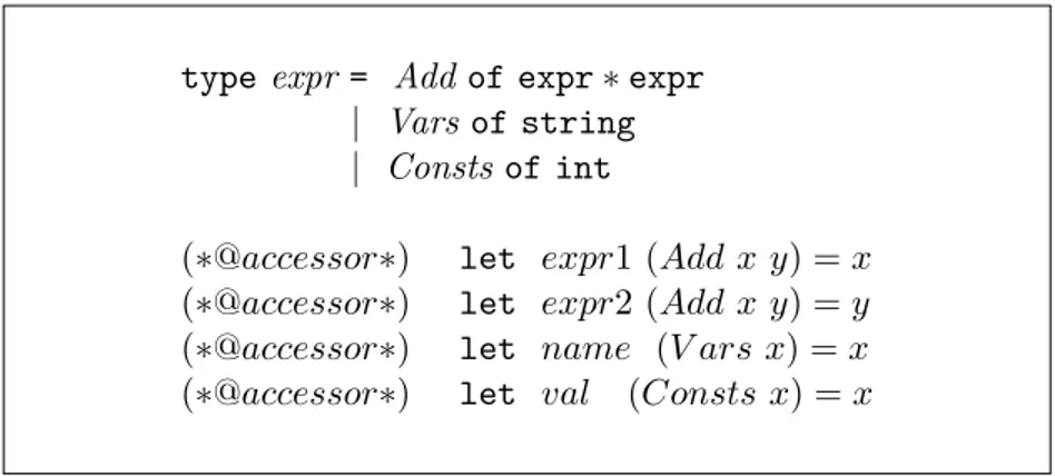
3.5 Data Type “expr” and its Accessor Functions in Caml . . . 46
3.6 Isabelle Grammar of Data Types used in this Thesis . . . 47
3.7 Syntax of Accessor Functions in Isabelle . . . 47
3.8 Datatype Meta-model . . . 48
5.1 Examples of Untranslatable Models . . . 66
6.1 BDDs Representing the Formula “a∨b” . . . 80
6.2 Adopted Approach in the Implementation of the BDD Case Study . . . 81
6.3 Architecture of the Case Study . . . 82
6.4 Data Type for Boolean Formulas in Isabelle and its Accessors Functions . . 83
6.5 Formula-Generated Meta Model . . . 83
6.6 BDD Type Definition and its Accessors Functions in Isabelle . . . 84
LIST OF FIGURES
6.8 Xtext Grammar for Boolean Formulas . . . 85
6.9 Logical Formula Displayed in a Generated Textual Editor . . . 87
6.10 Resulting BDD Tree Displayed in a Generated Graphical Editor . . . 87
7.1 Datatype to Ecore Implementation Architecture . . . 91
7.2 Statements Meta-model . . . 92
7.3 Data Types for Safety Critical Java in Isabelle (1) . . . 94
7.4 Data Types for Safety Critical Java in Isabelle (2) . . . 95
7.5 Examples of Accessor Functions for Safety Critical Java in Isabelle . . . 96
7.6 Resulting Ecore Diagram . . . 97
7.7 Counter-Example for Bidirectionality . . . 103
A.1 Vue d’ensemble de la méthode de transformation . . . 120
C.1 Sous-ensemble simplifié du méta-modèle de Ecore . . . 130
D.1 Grammaire de types de données utilisées dans cette thèse (en Caml) . . . . 135
D.2 Syntaxe des fonctions d’accesseur (en Caml) . . . 135
G.1 Exécution de l’étude de cas . . . 146
G.2 Type de données correspondant à la formule logique et ses accésseurs en Isabelle . . . 147
G.3 Résultat de la traduction du type de donnée pour les formules logiques . . . 147
G.4 Type de données correspondant à la définition de BDD et ses accésseurs en Isabelle . . . 147
G.5 Résultat de la traduction du type de donnée pour les BDDs . . . 147
H.1 Architecture de l’implementation de al fonction Datatype to Ecore . . . 150
LIST OF TABLES
List of Tables
4.1 Correspondence between Grammar and Transformation Rules . . . 53 5.1 Table Summarizing the Transformation Rules from Ecore Meta-models to
Introduction
Context and Motivation for this Thesis
The PhD thesis described in this document has been carried out in Toulouse that has become the center of the European aerospace industry. This has created a strong demand for systems and software in a field which is often referred to as Embedded Software. This software is complex and is required to be failure-free. In contrast to software that we use in our everyday life (games, web, email ...), defects on critical software can lead to considerable financial loss or even endanger human life. This is why this software is called Safety Critical Software. To ensure the high quality requirements, industrials rely on formal methods to certify their applications.
In fact, formal methods (such as interactive proof assistants [73,29]) are increasingly used in software engineering to verify the correctness of software. They have a solid formal basis and a precise semantics, but they use complex notations that might be difficult to understand for unaccustomed users. This becomes a problem when collaboration is needed between interactive proof professionals and experts of an applicative domain. In fact, these experts often have trouble to see precisely how their system specifications are represented in the proof assistants.
Instead, domain experts are often used to interact with the tools and formalisms pro-posed by Model Driven Engineering (MDE) [19, 84]. This method can rely on its visual specification languages such as class diagrams [45] that use intuitive notations. These di-agrams allow to specify, visualize, understand and document software systems. However, they suffer from a lack of precise semantics. Also, they do not allow to perform any verifi-cation on systems. We are interested in combining these two complementary domains that are formal methods and MDE by translating the elements of the one into the other.
One possible scenario is to define the abstract syntax of a Domain Specific Language (DSL) [94] to be used in the context of a formal verification, and then to generate a corre-sponding meta-model. Inversely, the meta-model can then be modified by an application engineer and serve as basis for re-generating the corresponding data types. This operation may be used to find a compromise between the representation of the application engineer’s wishes on the meta-model and functional data structures used in the proof. Furthermore, the meta-model can be used to easily generate a textual (or graphical) editor.
Overview of our Approach
Overview of our Approach
In order to translate functional data types (used in interactive provers like Coq or Isabelle) into class diagrams and vice versa, we use an MDE-based transformation method. This method allows to define a generic transformation process from functional data types to meta-models and backwards.
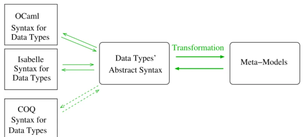
FigureA.1shows an overview of our approach. In the first direction of the translation, we derive a meta-model of data types starting from an EBNF representation of the data type definition grammar [73]. This meta-model is the source meta-model of our transfor-mation. The class diagrams are represented using Ecore: the core language of the Eclipse Modeling Framework [51]. The latter is comparable to EMOF (the class diagram stan-dard recommended by the OMG). We describe then a subset of the Ecore meta-model to be the target meta-model. The transformation rules are defined on the meta-level and map elements from the source meta-model to their counterparts in the target meta-model. The DataTypeToEcore function implements these rules in Java. It takes as input models which conform to the source meta-model and returns their equivalent in a model which conforms to the target meta-model. We use the mapping between the constructs of the two meta-models to define the reverse direction of transformation rules.
Meta−Model Datatype Functional Grammar of a Datatype’s EBNF representation Meta−Model Ecore Ecore Definition Datatype Model
<<ConformsTo>> <<ConformsTo>> <<ConformsTo>>
Transformation Rules Transformation Rules Ecore To Datatype Datatype Model Datatype To Ecore <<Implements>> <<Implements>>
Figure 1: Overview of the Transformation Method
Bidirectionality [91] is one of the desired options of MDE-based transformations. In-deed, assuming we start from a source model MS, then we perform a transformation using a function f to get a target model MT. It is important to derive an equivalent model to
MS, as a result to the application of f−1 on MT. In our case, such a feature requires more
restrictions on the Ecore models. This property is only guaranteed when the source model is the data types model (for more details see discussion on page102). The implementation of most of the transformation rules of the two sides has been successfully performed in an
application.
Our work aims at narrowing the gap between interactive proof and meta-modeling by offering a way to transform data structures used in interactive provers to meta-models and vice-versa. Furthermore, the generated meta-model can be used to easily generate textual (or graphical) editors using Xtext (respectively GMF: Graphical Modeling Framework) facilities [51].
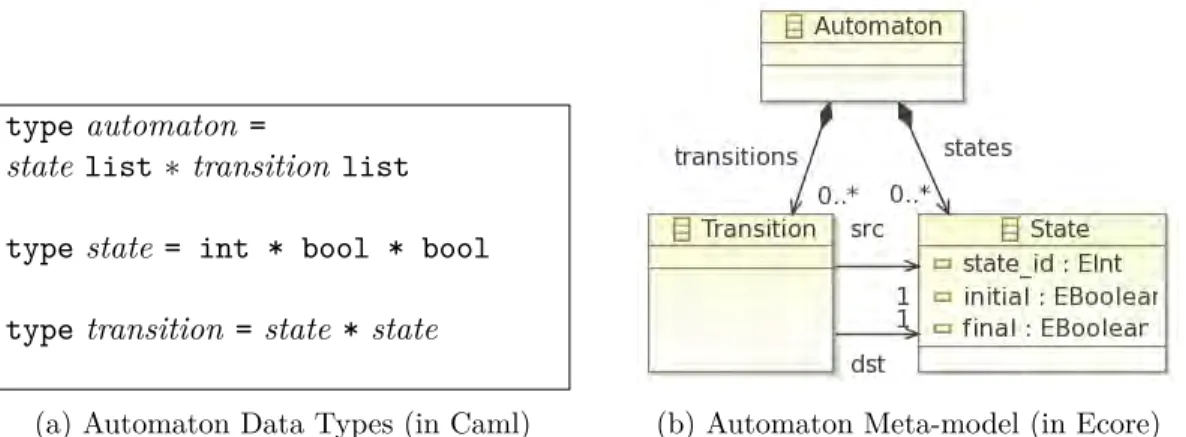
Example: Figure2shows an example of the application of our transformation approach to an automaton description. The left part of the figure (2a) represents a data type description of an automaton, in this case written in the Caml language. Each automaton is then composed of a list of states and a list of transitions. Every state is composed of an integer value (for identifying the state) and two Boolean values (defining whether a state is an initial state and/or a final state). A transition is then described by two states, a source and a target. The right part of the figure consists in the representation of the same automaton as a meta-model in Ecore. This meta-model represents the result of applying our transformation on the presented data types.
type automaton =
state list ∗ transition list type state = int * bool * bool type transition = state * state
(a) Automaton Data Types (in Caml) (b) Automaton Meta-model (in Ecore)
Figure 2: Example of the Application of our Approach
Contributions
The contributions of this thesis consist in several achieved goals that are presented in the following:
• We define a subset of data types descriptions which are common to functional lan-guages (SML, Caml, Haskell) and the Isabelle proof assistant. This subset contains the essential elements needed to describe the shapes that data types take in every-day
Contribution
practice, including the use of parameterized types. We then construct the correspond-ing meta-model representcorrespond-ing this subset, startcorrespond-ing from the EBNF grammar of the subset.
• We define a subset of the Ecore meta-model which at the same time is expressive enough to model the basic class diagrams and also contains elements that are translat-able to functional data types. The meta-models are essential to apply an MDE-based transformation approach.
• We describe in a first direction a fully-automated MDE-based transformation process from functional data types to meta-models. We particularly pay attention to write transformation rules that cover the whole defined subset of data types. In order to ensure the validation of our generated meta-models in Ecore, we propose some well formedness constraints on the translated data types.
• We introduce the transformation in the opposite direction: from meta-models to data types. After studying all the possible patterns that may appear in the meta-model, we select the translatable ones. This step requires to postulate some well-formedness conditions insuring the correctness of the generated data types.
• Most of the transformations described in this thesis are implemented using Java and EMF as an application that is used in case studies. We couple this work with both the generation of graphical (and/or textual) editors and generation of certified object oriented code.
• We illustrate the feasibility of our approach with two case studies. The first consists in the construction of Binary Decision Diagrams with subtree sharing using certified code generation. The second defines a DSL named Safety Critical Java: a Java-like language enriched with timing annotations.
Publications Our work has resulted in the following publications:
• Selma Djeddai, Mohamed Mezghiche, and Martin Strecker. A case study in combining formal verification and Model-Driven Engineering. In Vadim Ermolayev, Heinrich C. Mayr, Mykola Nikitchenko, Aleksander Spivakovsky, Grygoriy Zholtkevych, Mikhail Zavileysky, and Vitaliy Kobets, editors, ICTERI, volume 848 of CEUR Workshop Proceedings, pages 275–289. CEUR-WS.org, 2012.
• After a second selection, an extension of our paper (accepted in the previous confer-ence) has been published as post proceedings in :
Selma Djeddai, Mohamed Mezghiche, and Martin Strecker. Combining verification and MDE illustrated by a formal Java development. In Vadim Ermolayev, Heinrich C. Mayr, Mykola Nikitchenko, Aleksander Spivakovsky, and Grygoriy Zholtkevych,
editors, ICT in Education, Research, and Industrial Applications, volume 347 of Communications in Computer and Information Science, pages 131–148. Springer Berlin Heidelberg, 2013.
• Selma Djeddai, Martin Strecker, and Mohamed Mezghiche. Integrating a formal de-velopment for DSLs into meta-modeling. In Alberto Abelló, Ladjel Bellatreche, and Boualem Benatallah, editors, MEDI, volume 7602 of Lecture Notes in Computer Sci-ence, pages 55–66. Springer, 2012. An extension of this paper has been submitted to the Journal of Data Semantics (JoDS).
Outline of the Thesis
This PhD document is organized as follows:
Chapter1describes the basic notions of MDE and model transformation. It also gives an overview of related work consisting in different approaches aiming at combining formal verification and MDE. Chapter2consists in the presentation of our chosen meta-modeling framework: Eclipse Modeling Framework. Chapter 3 fixes the formal framework used in the rest of the thesis. Here, we introduce some Caml and Isabelle constructs.
The core contributions of this PhD are given in Part II. Chapter 4 and Chapter 5 introduce respectively our two-way transformation from functional data types to class diagrams (represented in Ecore) and back from class diagrams to data types. As for Chapters 6 and 7, they illustrate our contributions by two case studies: Binary decision diagrams and Safety Critical Java. We finish this document by drawing a conclusion and citing the perspectives of this work.
Chapter 1
Scientific Context and Related
Work
1.1
Introduction
This thesis consists mainly in the transformation of data types used in functional pro-gramming into class diagrams and vice versa in the context of Model Driven Engineering (MDE). This is why we need to clearly define the basic concepts of MDE.
In this chapter, we give an overview of the basic concepts of MDE. We start in Sec-tion1.2by introducing the notions of Model and Meta-model along with defining the MDA standard. Then, in Section1.3we define Model Transformation and some model transfor-mation approaches. We illustrate these approaches with model transfortransfor-mation tools (that implement each approach). We finish the section with conclusions that explain the reasons that lead us to choose our implementation approach for the transformation process.
Section 1.4 consists in a presentation of a subset of the related work. At first, we introduce existing approaches aiming at the integration of MDE and formal methods in general. Then, we detail the most related approaches to our work: the transformations between class diagrams and formal frameworks. We finally position our approach in the summary (Section1.5).
1.2
Model Driven Engineering
Model Driven Engineering (MDE) is a software development methodology where the models are the central elements in the development process. It is a particular kind of generative engineering in which all or parts of an application is engendered from a model.
In order to describe and develop a system, MDE embodies a stepwise refinement process and allows to describe the software architecture (in the jargon called business knowledge) independently of the technical platform. Basically, MDE was triggered by object
technol-CHAPTER 1. Scientific Context and Related Work
ogy: in fact, after the “everything is an object” MDE prones the “everything is a model” [18]. It provides a large number of modeling views that allow to express separately the concerns of users, designers, developers . . . . Its main objective is to develop, maintain and evolve software by performing model transformations.
Before going further into the definition of principles related to the MDE, it seems necessary to introduce models and meta-models.
1.2.1 Model and Meta-Model
In MDE, the models are the primary artifacts of the development life-cycle. Despite this, there is no unique definition of what a model is. In fact, the MDA guide [74] defines a model as follows: “a model of a system is a description or specification of that system and its environment for some certain purpose. A model is often presented as a combination of drawings and text. The text may be in a modeling language or in a natural language”; while in the MDA Explained book [65], “A model is a description of a system written in a well-defined language.” As for Bézivin & Gerbé [20] “A model is a simplification of a system built with an intended goal in mind. The model should be able to answer questions in place of the actual system.”
A meta-model defines elements of a language allowing to express models. It describes the different kinds of model components and the way they are arranged and related [19]. The instances of the meta-model elements are used to construct a model of the language.
Meta-models are used to define the abstract syntax of languages belonging to a partic-ular domain: Domain Specific Languages (DSL). They constitute the heart of MDE. 1.2.2 Domain Specific Languages (DSL)
In the literature, there are several definitions for what is a DSL. According to [94], a Domain Specific Language (DSL) is: “a programming language or executable specification language that offers, through appropriate notations and abstractions, expressive power focused on, and usually restricted to, a particular problem domain”.
1.2.3 Model Driven Architecture
The Object Management Group (OMG) [75] defined the Model Driven Architecture (MDA) standard [65, 20], as specific incarnation of the MDE. MDA promotes the use of models in different phases of software development. The basic idea is to separate the business logic description from any technical platform. While this idea is not new, using models is preferred over classical programming languages.
The development cycle of MDA does not seem very different from the classical devel-opment cycle which is mainly based on the phases of analysis, design, coding, testing and deployment. The main difference lies in the nature of the artifacts created during the development phase: models.
1.3 Model Transformation
MDA classifies models in three categories: Computation Independent Model (CIM), Platform Independent Model (PIM) and Platform Specific Model (PSM). In these models, the developed system is described at different levels of abstraction. According to the MDA guide [74], these models are defined as follows:
• CIM: “is a view of a system from the computation independent viewpoint. A CIM does not show details of the structure of systems. A CIM is sometimes called a domain model and a vocabulary that is familiar to the practitioners of the domain in question is used in its specification”.
• PIM: “is a view of a system from the platform independent viewpoint. A PIM exhibits a specified degree of platform independence so as to be suitable for use with a number of different platforms of similar type”.
• PSM: “is a view of a system from the platform specific viewpoint. A PSM combines the specifications in the PIM with the details that specify how that system uses a particular type of platform”.
1.2.4 The Four-Layer MOF Meta-modeling Architecture
Simplification or abstraction is the essence of modeling. The OMG defines a modeling ar-chitecture called “The Four-Layer Meta-modeling Arar-chitecture” as presented in Figure1.1. According to this architecture there are four levels of modeling:
• M0 level: the level of real (concrete) data one wants to model. These data provide an instance of the model level depending on the M1 level.
• M1 level: the model level that allows to write data at M0. Typically a UML model belongs to this level. Models belonging to this level are described by a meta-model level M2.
• M2 level: to this level belong meta-models of description languages, typically the UML meta-model or EMF.
• M3 level: the meta-meta-model level. The OMG defines a single language for defin-ing meta-models called the Meta-Object-Facility (MOF) [75]. It allows to describe, extend or modify meta-models. MOF is self-describing, it can describe its semantics itself.
1.3
Model Transformation
Model transformation is one of the key techniques of the field of MDE. The principal moti-vation behind model transformation is the ability to automate routine aspects of processes in order to make software development and maintenance more efficient.
CHAPTER 1. Scientific Context and Related Work meta−metamodel meta−model model system M3 M2 M1 M0 conformsTo conformsTo conformsTo representedBy The real world modeling world The
Figure 1.1: Meta-modeling Layers [18]
Kleppe et al [65] define a transformation as “the automatic generation of a target model from a source model, according to a transformation definition. A transformation definition is a set of transformation rules that together describe how a model in the source language can be transformed to a model in the target language. A transformation rule is a description of how one or more constructs in the source language can be transformed to one or more constructs in the target language”.
Figure1.2 represents a typical MDE transformation pattern. A transformation defini-tion is then represented by a mapping from elements of the source meta-model (Language 1) to those of the target meta-model (Language 2). Consequently, each model conforming to the source meta-model can be automatically translated to an instance model of the target meta-model using a transformation tool that implements the transformation definition. The transformation definition (which is itself a model) is written in a meta-language that extends the standard meta-language (the meta-meta-model (MOF)).
Model transformation is often associated with the MDA approach. Indeed, the imple-mentation of MDA is completely based on the definition of models and their transforma-tions. To do this, the OMG proposed a formalization and standardization of techniques for the transformation of models to ensure compatibility between MDA tools. This standard is known as QVT.
QVT stands for Query/View/Transformation [77]. It is the standard language recom-mended by the OMG to specify Model transformation in the domain of MDA [66]. It defines three sublanguages for transforming models: the Relations language and the Core language which are declarative and the Operational mappings language which is specified as a standard way for providing imperative implementations.
1.3 Model Transformation extends used metalanguage language definition transformation writen writen in is is in in is writen Transformation definition language 2 language 1 in is is in writen writen
model 1 Transformation model 2
tool by is
Figure 1.2: Pattern for MDE Transformations [65]
The Object Constraint Language (OCL) [76] is a language used to express con-straints on class diagrams. It allows to describe invariants on MOF models/meta-models in a textual format. It is usually associated with UML. It constitutes an important part of the QVT standard for model transformation. It is not a transformation language in the strict sense but it is used by some transformation tools for the navigation in models.
1.3.1 Classification of Model Transformation Approaches
Model transformation approaches can be classified depending on several criteria. They can be classified according to the target meta-model of the transformation. In fact, when the source and target meta-models (languages) are identical, it is an endogenous transforma-tion. When they are different, it is exogenous.
CHAPTER 1. Scientific Context and Related Work
transformation: Model-to-model and Model-to-text. The model-to-model transformation gives a model as a result of the transformation, while model-to-text approaches generate code.
This section is mainly about the classification of Model-to-model approaches, based on this survey [31].
Direct Manipulation Approaches In this category, the implementation of transforma-tion rules, scheduling (i. e. the sequencing of conflicting rules), tracing and other facilities is performed by the user in a programming language (as Java for example). They are then implemented as object oriented framework that provides only an internal model represen-tation and some API to manipulate it.
Operational Approaches This kind of approaches is comparable to direct manipulation approaches with a more dedicated support for transformation. They are usually based on an existing meta-modeling formalism that is extended in order to allow modeling the behavior of meta-models. Several systems implement this solution for model transformation such as QVT Operational mappings [77] and Kermeta [72]. This latter is described more in detail in Section 1.3.2.5.
Relational Approaches As its name implies, this type of approaches is based on the mathematical notion of a relation and uses declarative transformation rules. The basic idea is to specify relations among the source and target model elements. This category of approaches supports multi-directional rules and usually requires to separate source and target models. Examples of implementations of relational approaches: QVT Relations [77] and AMW [35].
Graph Transformation Based Approaches They are based on graph transformation theory. The source and target meta-models are represented as graphs. The transformation rules are formed of a LHS and RHS. When applying a transformation rule, the LHS is matched in the source model to be replaced by the RHS in the target model. Examples of systems in this category: VIATRA [95], GReAT [3], AGG [92] (Section 1.3.2.1), AToM3 [32] (Section 1.3.2.2) and Moflon [7] (Section1.3.2.3).
There are also hybrid approaches that use a mix of different approaches for transforming models. We can cite the ATL tool [62] that implements a combination of imperative and declarative constructs in the transformation definition. This tool is described more in detail in Section 1.3.2.4.
1.3 Model Transformation
1.3.2 Model Transformation Tools
In this section, we present different model transformation tools that implement some model transformation approaches presented in the previous section. We then explain the reasons that lead us to implement our transformation process using a direct manipulation approach in Java (see Section 1.3.2.6). For more in-depth discussions and comparisons, the reader can refer to the articles [41,90,97,80].
1.3.2.1 The Attributed Graph Grammar (AGG)
The Attributed Graph Grammar system (AGG) [92, 2] is a graph transformation tool developed at Technische Universität Berlin. Unlike other transformation tools, AGG has solid formal bases on Category Theory and implements attributed graph grammar.
Meta-models are represented with graphs (called type graphs) allowing the inheritance mechanism and multiplicities while models are represented with attributed graphs.
It provides a graphical mode that is well adapted for expressing rules.
In AGG, there is no distinction between the source and target meta-models. The type graph defined merges the two. It therefore implements only endogenous transformations.
AGG offers two execution modes (for applying the transformation rules): interactive mode and interpreter mode. In the first mode, the user can choose the rules to be applied while in the second the transformation engine chooses the right rules to be applied. In this case, transformation rules can be classified by layers, depending on when they will be executed. In AGG, it is also possible to express priority between rules. In fact, if two rules can be executed on the same sub-graph, the one which has the highest priority is chosen to be run, else the choice is made in a non-deterministic manner. Also, it provides a way to express patterns preventing a rule application (Non-Applicability Conditions (NAC)). It shows when a particular rule has not to be executed for a special shape of the sub-graph.
AGG has formal foundations. It is based on category theory. It concentrates on struc-tural analysis aspects. It offers type checking functionalities on graphs and rules. Actually, it checks whether the transformation rules and graphs correspond to the type graph de-scription. It is possible to disable or enable this functionality (partly or totally). It also looks for conflicts between rules and checks termination criteria.
One of the disadvantages of AGG is the lack of model exchange formats. However, it is implemented in Java and thus its transformation engine is usable by a Java API.
Since 2010, it is possible to use a tool that is close to AGG named Henshin [21, 55]. The latter is also developed at the University of Berlin. However, it is implemented on Eclipse and uses models described in EMF. Henshin provides easy exchange of models with AGG.
CHAPTER 1. Scientific Context and Related Work
1.3.2.2 AToM3
AToM3 (A Tool for Multi-formalism and Meta-Modeling) [32, 16] is a tool for designing domain specific languages and model transformation. It is developed at McGill University of Montreal, Canada. It allows to define the abstract and the concrete syntax of a DSL using meta-modeling in order to generate a customized modeling environment for the developed DSL. It also permits to perform model transformation by applying graph transformation. Moreover, it offers a way to generate environments for Multi-View Languages.
AToM3 uses UML-like meta-models [33] and manipulates them as graphs. It provides a graphical mode that is suitable for model transformation. Attribute values can also be specified textually by Python code.
The model transformation approach that implements AToM3 is triple graph grammar. This approach is cleaner than regular graph grammar since it is based on three graphs: one for the source model, one for target model and a third one for the correspondence graph. The latter is hidden to the users, it is simply used to maintain the consistency between the source and target models.
Updating models is particularly developed in AToM3. Indeed, it can perform transfor-mation in an incremental way. When adding elements in the source model, it is possible to execute again the transformation and update the target model (due to the persistence of the correspondence graph).
AToM3 comes along with some exchange format supported as XMI.
AToM3 is a complete tool: it permits to perform model transformation, as well as to define the abstract and concrete syntax of a DSL in order to use it in a graphical or textual editor. It also facilitates the update mechanism of the models and allows the reuse of rules. However, its verification capabilities are very low compared to those proposed by AGG for example (consisting only in checking the correct typing of the target model).
1.3.2.3 MOFLON
MOFLON [7,70] is a meta-modeling environment developed in the Real-Time Systems Lab at Technische Universität Darmstadt. It provides full support for MOF 2.0 (modularization and refinement concepts). It thus allows MOF meta-modeling, graph transformation based on graph grammar; verifying some properties (OCL constrains) on models and generating Java code for models and transformations. The major goal of MOFLON is the conformity with standards as MOF 2.0.
MOFLON is based on the Fujaba Toolsuite [38] which uses graph transformation for UML-like graph schemata. In fact the TGG (Triple Graph Grammar) editor and the SDM (Story Driven Modeling) editor has been adapted from Fujaba. These two editors allow to perform respectively bidirectional and unidirectional transformations. The transformation process is supported by visual editors except for the OCL part (for describing constraints). The MOFLON tool provides several ways to represent the meta-models. Indeed, they can be implemented using commercial tools like Rational Rose or directly specified with
1.3 Model Transformation
MOF 2.0 editors. It also allows the exchange with other existing modeling environments by providing the ability to import and export meta-models as XMI.
MOFLON does not offer support for the representation of the concrete syntax of DSLs. Its developers claim that it is mainly dedicated to the adaptation of existing tools for DSLs (having existing concrete syntaxes) [8].
In 2011, MOFLON has been completely re-engineered into eMoflon [13]. The model transformation tool has been combined with the EMF and Eclipse technologies. The main reasons that led to re-engineer Moflon is the important role that EMF has taken these few last years in research. In fact the developers claim that EMF has become the de-facto standard in the meta-modeling community.
1.3.2.4 The ATLAS Transformation Language
ATL [62,15] is a model to model transformation tool developed at Université de Nantes, France by the ATLAS team. The transformation process (rules and helpers) is expressed textually in the ATLAS language. It has been created as an answer to the OMG QVT language request. It is considered as a hybrid textual language, it mixes declarative and imperative style. This language is composed of Rules, Helpers, Queries and Libraries. The rules can be divided in two categories:
• Declarative rules consisting of matched rules and lazy rules. Lazy rules are applied only when they are called by another rule.
• Imperative rules represented by called rules.
Helpers can be viewed as an ATL equivalent to methods in Java. They are specified in OCL and are used to navigate in the source meta-model. They can be called from anywhere in the ATL program. Thanks to helpers, ATL is suitable for the navigation on the meta-model.
It is implemented as an Eclipse plug-in and is well adapted to all the Eclipse modeling tools and functionalities. ATL has a different execution mode for endogenous transforma-tions (target and source meta-model are the same), it is called: Refining mode.
When using ATL, we realized that besides its advantages cited previously, there were some negative points. The first one is about its complex syntax. The existence of helpers in addition to different sorts of rules makes the syntax heavier. Moreover, these different parts of an ATL program may use common constructs but which are syntactically expressed differently depending in which part they are used. This may lead to confusions. (For example the syntax of the “if” instruction has different syntaxes in helpers and matched rules).
Also in ATL, the type checking of rules is relatively weak. It consists mainly on a syntactic verification. Actually, the user can generate wrong elements in the target meta-model.
CHAPTER 1. Scientific Context and Related Work
In addition, to our knowledge, in ATL there is no predefined way to represent priorities on rule executions. It is even rather complicated to declare these priorities whenever there are different combinations of rules (Matched and Called rules).
1.3.2.5 Kermeta
Kermeta [72] (for a Kernel metamodeling language) is a tool developed by the team Triskel at Université de Rennes 1, France. It is a meta-programming environment allowing to simulate the execution of meta-models. Usually, this tool is dedicated to represent the operational semantics of meta-models for testing and simulation purposes. To achieve this goal, the developers used aspect oriented modeling to build an executable meta-language by composing action meta-models with class diagram meta-languages. In other words, the meta-language of Kermeta is based on Essential MOF (EMOF) 2.0 [75] which was extended by classes allowing to describe the semantics of operations on meta-models by defining a support for actions. The action language of Kermeta is imperative and object-oriented.
The meta-model of Kermeta can be divided into two parts; structural and behavioral. The structural part is represented by the EMOF meta-model while the behavioral consists of a class named expression and its subclasses. This part is used to specify the semantics of operations [71].
In the model transformation point of view, the approach of Kermeta is classified among the operational approaches of model transformation [31]. The part in the meta-model of Kermeta allowing to define operations is used to define transformation functions while the structural part is used to define models. For example, in Kermeta a transformation rule AToB is defined as an operation of the model element A with B as its return type. Then, in Kermeta, instead of handling the source and target models, the user manipulates the objects of the transformation itself which is also a model.
In order to validate model transformations, Kermeta provides a unit test framework (KUnit) based on JUnit (the Java framework for performing unit tests).
Kermeta is a powerful and expressive language, but it lacks simplicity and clarity. Unlike rule based transformation languages, Kermeta does not separately define target and source models [90].
Kermeta is available as an Eclipse Plug-in and offers a bridge towards the Eclipse Ecore formalism.
1.3.2.6 Synthesis
In the part devoted to the bibliography, we tested and experimented with several trans-formation tools to choose the approach that we will adopt for the implementation of our transformation. For each of the approaches presented further in the section, we experi-mented at least one tool.
Graph transformation tools (here AGG, AToM3 and Moflon) permit to define source
1.4 Related Work
and target meta-models all along with a set of transformation rules and use graphical representations of instance models that ease the transformation process. AGG is best suited to endogenous transformations. Also, it offers more verification options than other tools (even if they are purely syntactic). AToM3 is particularly useful when transforming DSLs. Indeed, it is the only tool that offers a way to describe the concrete syntax (whether textual or graphical) of the processed DSLs. Moflon is dedicated to the transformation of already existing tools. It offers various exchange formats with other modeling tools. Kermeta offers a rich and expressive but complex transformation environment. Finally, ATL is particularly well-suited for injective transformations (that use principally declarative rules).
In general, the tools presented above offer weak verification functionalities. In fact, they are often limited to syntactic aspects (such as confluence of transformation rules) and do not allow to model deeper semantic properties (such as an operational semantics of a programming language and proofs by bisimulation). Also, when using one of the tools presented previously, we do not always know precisely how transformations are performed. So we ended up opting for an approach of direct manipulation (using the EMF frame-work and Java). The encoding of our transformation rules is carried out in Java. However, they are written formally in a functional style (as if they had been written in Caml). The underlying model structure is provided by EMF.
1.4
Related Work
In this thesis, we are interested in bridging the gap between Model Driven Engineering and formal methods. Our main contributions consist in transforming data type structures used in functional languages into class diagrams (represented in Ecore) and vice-versa. This section contains the essential related work. We start by spelling out some approaches aiming at integrating formal methods and MDE in different ways. Next we present closer work: the transformation of class diagrams to formal languages, allowing to perform proofs.
1.4.1 Formal Frameworks and Model Driven Engineering
Despite its advantages, MDE suffers from a lack of solid formal basis. To remedy this shortcoming, different research teams are working on integrating MDE with existing formal methods. These formalizations can occur on different parts of the MDE. Indeed, they may occur on models (or meta-models), model transformation [28, 67, 9] or directly at DSL level [22, 12, 43]. Here, we are particularly interested in the interaction of MDE and formal languages in terms of class diagrams.
In this category, we start by presenting the work of Richters [83]. The author presents a formal definition of UML Class diagrams and OCL semantics using set theory and first order logic. His approach has been used to detect inconsistencies and to validate well-formedness rules of the UML 2.0 Standard. It then has been implemented as a tool for
CHAPTER 1. Scientific Context and Related Work
the specification and the validation of systems (UML/OCL) : the USE tool (UML-based Specification Tool) [50].
The following approaches are concerned with the description of modeling frameworks in proof assistant environments as Coq [29] and Isabelle [73].
1.4.1.1 Coq4MDE
Coq4MDE [93] is a proof environment for describing aspects of MDE with the aim of giving formal foundations to MDE. To do so, the developers define the notion of model and reference model (actually meta-model). They also introduce two fundamental relations for MDE: conformsTo and promotion. The conformsTo relation “indicates whether a model is valid with respect to a reference model” while promotion “builds a reference model from a model”. The consistency of the approach is validated by proving (using the Coq proof assistant [29]) that EMOF is self defined.
In [63], Coq4MDE is extended to support composition of model elements. This work consists in the formalization of composable verification technologies in order to ease the integration of pre-verified components.
In a more general approach [82], C.Picard worked on interfacing MDE and Type Theory [30] by using the Coq interactive theorem prover. The author represents meta-models as graphs and performs some proofs on these graphs in order to certify that the application of transformations on these graphs ensures some properties regardless of the input model. 1.4.1.2 A Formal Proof Environment for UML/OCL
A.D. Brucker [23] has worked during his PhD thesis on the encoding of object oriented specifications in the Isabelle/HOL interactive prover.
The tool HOL-OCL [25] is an interactive proof environment for UML class models annotated with OCL [76] specifications. It is based on a repository for UML/OCL models and Isabelle/HOL [73]. This system provides a way to run proofs on UML meta-models. It consists of:
• a repository used to import UML models in an XMI format.
• a package allowing to encode object oriented components into HOL. • a library providing the theorems needed for performing verification. • a suite of automated proof procedures.
This system was later extended with the ability of processing models by model transfor-mation and code generation [24].
1.4 Related Work
To sum up, A.D. Brucker has defined a formal proof environment for the object-oriented world and MDE. To do this, he used a shallow embedding approach by encoding object oriented data structures and MDE in HOL. However, such a functional and formal envi-ronment is not well suited for representations of object-oriented components. This gives rise to a complex environment that makes the proof process more difficult in Isabelle.
The transformation is one of the means used to establish the links between the formal languages and the languages provided by the MDE. It allows to describe a system using a formal language, but also to represent the same system using a more intuitive description language. This topic is discussed in the next section.
1.4.2 From Class Diagrams to Formal Languages and Back Again
EMF (Eclipse Modeling Framework) [27] models are comparable to Unified Modeling Lan-guage class diagrams [45]. For this reason, we are interested in the mappings from other formal languages to UML class diagrams and back again. Some research is dedicated to establishing the link between these two formalisms.
The integration of formal and semi-formal notations has been investigated for several years [46]. Among the first experiments of transformations between class diagrams and formal languages were transformations into Z [60]. In fact, Kim et al. worked on using Z as underlying semantics for UML diagrams [64] while Evans et al. worked on the effective transformation of UML models to Object Z [42].
In the next subsections, we present some work related to the transformations between formal languages and Class diagrams. We begin with transformations between UML and B, then between Alloy and UML, and finally Focal and UML. To our knowledge, there is no work for the translation of data types (used in functional languages) into class diagrams (or in the opposite direction).
1.4.2.1 B To UML and Back Again
Much of the work done for the transformations between class diagrams and formal lan-guages has chosen the B language as formal part. B [1] is a formal method that allows to construct a program by successive refinements, using abstract specifications.
In order to specify the semantics of UML and benefit from verification tools provided by the B method, several studies have been conducted to translate UML to B. This was achieved by the development of several tools of translation, including UML2B [54] and U2B [86,87]. In this work, the translation rules are missing solid semantics because they are defined in natural language.
The transformation of UML to B has been a little less explored. We can cite the thesis J-C. Voisinet [96,52] and work conducted by H. Fekih [44].
Ossami & al. [79] adopt a different approach to establish the link between UML and B. The approach consists in a joint and simultaneous development of two views of a system
CHAPTER 1. Scientific Context and Related Work
(in UML and B) while maintaining the traceability and consistency between the two views. Work of Idani & al. We present this work in a separate paragraph because it is different from the ones cited previously. It is the only translation from B to UML (and vice-versa) that uses meta-model based transformation while the others only use simple translations. In his PhD thesis [56], A.Idani studies the derivation of UML diagrams starting from B specifications. He uses a generic process based on a structural and semantic mapping between UML and B constructs in order to perform a model driven transformation.
This approach consists in two steps. First, some transformations of static parts of the B specifications to UML class diagrams are presented with the purpose of documenta-tion. Next, using defined pertinence criteria, the user selects the adequate transformation rules. Then, an algorithm is proposed to perform the transformation. This phase is semi-automated, a user intervention is still necessary for the selection of rules. The second step is about exploring the dynamic (behavioral) parts of a B specification for the derivation of UML state transition diagrams. To achieve this objective, the author uses graph ab-straction techniques in order to build automatically a state transition diagram. The whole approach is spelled out in [57].
In [58], the authors focus on the reverse side of the transformation (only for the static parts). They propose an evolutive framework to assist the derivation of formal B spec-ifications from UML class diagrams. This work is based on the structural and semantic mapping between UML and B static constructs along with a well-defined UML core with a set of safety commandments [59]. Starting from this safe UML model, a formal model of a B specification is built. A certifiable code can then be produced after a series of refinements and proofs using the Atelier-B tool [14].
This approach seems to be global and complete, however it includes drawbacks. In fact, the user is still solicited in order to choose the rules to be applied during the transformation process. Consequently, it is possible to generate two different UML diagrams starting from a single B description. Also, in the second direction of the transformation (from UML to B), it is not the usual UML version that is used but a modified one, Safe UML.
1.4.2.2 UML To Alloy and Back Again
Alloy [61] is a declarative textual modeling language based on first order logic that gives support for notions of object orientation. Its models are analyzed with a fully automated tool: the Alloy Analyzer.
Several studies have been performed to establish the correspondence between the UML class diagram (augmented with OCL [76]) and the components of Alloy. Some have estab-lished the mapping rules defined using natural language [69], while others have translated manually UML specification to Alloy [37,47].
In his PhD thesis [10], the author worked on an MDE based transformation approach for automatically generating Alloy specifications from UML class diagrams [11]. The purpose
1.4 Related Work
of the approach is to perform analysis using Alloy on UML models. The transformation is defined using a number of transformation rules from UML concepts to Alloy concepts. This work was realized by the development of a UML profile for Alloy.
In [85], the authors extended this work with a way to transform Alloy instance models to UML object models. This transformation is automatically generated from the transfor-mation that maps UML to Alloy in the first place. The process is implemented as follows. When transforming UML class diagrams into Alloy models, a trace of the transformation is produced. At this point, it is possible to use the Alloy analyzer in order to automatically perform a verification of the produced model. This analysis consists of either a simulation or an assertion checking. In the case of an assertion checking, the user checks if a property is valid on a model. If this is not the case, Alloy generates a counter-example (which is an instance of the Alloy model). Using the trace of the transformation in the first direction, the module Alloy To UML instance converter translates the Alloy counter example to a UML object diagram.
This approach offers the possibility of transforming a class diagram (in UML) into a model used by an automatic analyzer in order to perform proofs. It is clear that using an automatic analyzer is simpler than using an interactive prover (which requires a particular expertise of the user). However, the interactive provers are more powerful. Also, this approach offers no way to translate a model to UML class diagrams, it does so only at an instance level.
1.4.2.3 Focal To UML
Focal [39] is a formal language allowing to build certified applications gradually starting from abstract specifications to concrete implementations. This language includes elements inspired from object oriented programming as inheritance and parameterization.
In [36], Delahaye & al. describe a formal and sound framework for transforming Focal specification into UML models. It consists in an automatic translation of Focal specifica-tions into UML Class diagrams. This work aims at providing graphical documentation of formal models (described in Focal) to developers. To implement this approach, they started by defining a formal description for a subset of the UML Class diagram, represented by an EBNF grammar of the subset of UML. Then, this UML subset has been extended via the mechanism of profiles (provided by UML) in order to take into account the semantic characteristics of Focal. The transformation rules are then formally presented and used to establish the soundness of the approach. This proof is also presented in the cited paper.
This approach offers a formal and sound environment to transform Focal specifications into UML Class diagrams. This transformation is mainly used as documentation for the developers of the proven system. However, there is no transformation of UML class dia-grams into Focal specifications. This would provide a way for developers to interact with the proof expert in order to agree on a solution that would suit both parts.
CHAPTER 1. Scientific Context and Related Work
backwards but their formal representation is significantly different from our needs: func-tional data structures used in proof assistants.
1.5
Summary
In this chapter we have presented the basic concepts of MDE as well as some related work. To provide the translation of our data types to class diagrams (and vice versa) we use the MDE method, more particularly model transformation. Our transformation is exogenous and goes from a PSM to another PSM. Functional data types (like class diagrams) are self-descriptive. This implies that our transformation is situated on the M3 level of the four-layer meta-modeling architecture. Instances of data types and class diagrams (in Ecore) are located on the level below (M2).
In order to implement our transformation, we use a direct manipulation approach (of model-to-model approaches). This choice has been made after a study of several approaches and testing the tools that implement them.
Our work is situated in a general context of combining formal methods with the MDE. In order to perform this combination, we have chosen the transformation because this technique seems to be the best suited to take advantage of both frameworks for the purpose of defining a Domain Specific Language.
To the best of our knowledge, our study is the only one to propose a fully automatic bidirectional transformation from functional data types to meta-models. Moreover, it permits to use the resulting meta-model to easily generate a graphical or textual editor using Eclipse.
In the following part, we introduce the two frameworks that represent the two direc-tions of the transformation starting by the formalism of our meta-models Eclipse Modeling Framework.
Part I
Chapter 2
Eclipse Modeling Framework
2.1
Introduction
The work we are presenting in this thesis is mainly about the transformation process from data structures used in functional programming into class diagrams. To represent these class diagrams, there exist several languages where UML class diagram is the most famous. We choose to work with Ecore, the core language of Eclipse Modeling Framework (EMF) which is close to UML.
This chapter is structured as follow : First, we start by a general presentation of Eclipse and EMF, before a more detailed definition of Ecore. Then, we focus on the subject used in the thesis. Further, we precise the relation between UML and EMF. Finally, we introduce tools provided by Eclipse Modeling Project (EMP).
2.2
Overview of the Eclipse Modeling Framework
Let us first introduce Eclipse. It is an open source, extensible and polyvalent software project. It provides a highly integrated tool platform for software development as coding activities, modeling, design, testing, etc. Its architecture is based on the notion of plug-in. Each plug-in provides a certain type and number of functionalities in the context of the Eclipse Workbench.
Eclipse Modeling Framework (EMF) is an Eclipse framework for building applications based on model definitions. It unifies three technologies: Java, XML and UML. It allows to describe a model as a class diagram, class interfaces in the Java programming language or in the form of an XML schema. Moreover, it is possible to describe a model in one of these formats and generate it in the two others.
Ecore is the model that is used to describe and handle models in EMF. It has been developed as a small and simplified implementation of UML. It is self-descriptive. Its components are further developed in Section 2.3.
![Figure A.1 shows an overview of our approach. In the first direction of the translation, we derive a meta-model of data types starting from an EBNF representation of the data type definition grammar [73]](https://thumb-eu.123doks.com/thumbv2/123doknet/2095008.7511/22.918.238.735.516.776/figure-overview-approach-direction-translation-starting-representation-definition.webp)
![Figure 2.1: The Complete Ecore Meta-model [27]](https://thumb-eu.123doks.com/thumbv2/123doknet/2095008.7511/48.918.222.754.140.936/figure-the-complete-ecore-meta-model.webp)
![Figure 2.7: GMF Workflow [51]](https://thumb-eu.123doks.com/thumbv2/123doknet/2095008.7511/56.918.180.796.146.523/figure-gmf-workflow.webp)
![Figure 3.2: Syntax of Type Definitions in Caml [68]](https://thumb-eu.123doks.com/thumbv2/123doknet/2095008.7511/61.918.140.729.141.659/figure-syntax-of-type-definitions-in-caml.webp)