ÉCOLE DE TECHNOLOGIE SUPÉRIEURE UNIVERSITÉ DU QUÉBEC
THESIS PRESENTED TO
ÉCOLE DE TECHNOLOGIE SUPÉRIEURE
IN PARTIAL FULFILLMENT OF THE REQUIREMENTS FOR THE DEGREE OF MASTER IN AEROSPACE ENGINEERING
M. A. Sc.
BY
Rodolfo Hassam SOLÍS GRAYEB
COMBINED AVIONICS SUITE DEVELOPMENT FOR HIGHLY INTEGRATED APPLICATIONS
10TH OF MAY 2016
© Copyright
Reproduction, saving or sharing of the content of this document, in whole or in part, is prohibited. A reader who wishes to print this document or save it on any medium must first obtain the author’s permission.
BOARD OF EXAMINERS
THIS THESIS HAS BEEN EVALUATED BY THE FOLLOWING BOARD OF EXAMINERS
Mr. René Jr. Landry, Thesis Supervisor
Electrical Engineering Department at École de technologie supérieure
Ms. Ruxandra Botez, Chair, Board of Examiners
Automated Production Engineering Department at École de technologie supérieure
Mr. Claude Thibault, Member of the Jury
Electrical Engineering Department at École de technologie supérieure
Mr.Stéphane Blais, External Evaluator Marinvent Corporation
THIS THESIS WAS PRENSENTED AND DEFENDED
IN THE PRESENCE OF A BOARD OF EXAMINERS AND THE PUBLIC 29TH OF APRIL 2016
ACKNOWLEDGMENTS
I would like to thank the support of the people without which this project would have never been possible. First of all I would like to express my gratefulness to my director René Landry Jr. for giving me the opportunity of contributing to the remarkable efforts done at LASSENA. In the same way I would like to thank Omar Yeste who advised me throughout the course of this project and guided me both technically and at a personal level; his contributions and influence on my work are far beyond this project. I need also to recognize the resourcefulness and availability of my colleagues Joe Zambrano and Arthur Olivier who made my course through the project a more enjoyable one. My most sincere recognition to Abdessamad Amrhar, Besset Maxime and the rest of the LASSENA team members for their dedicated work, which allowed this project to succeed under the direction of Professor René Landry Jr.
Finnaly a special recognition to my parents and sister whom were always there to provide emotional support throughout the distance and had, most of the time, the right word of advice to share with me for every difficult situation during the course of the project.
DÉVELOPPEMENT DE SUITE EMBARQUÉE POUR UNE PLATEFORME AVIONIQUE LOGICIELLE HAUTEMENT INTEGRÉE
Rodolfo Hassam SOLÍS GRAYEB
RÉSUMÉ
Ancré dans le contexte des systèmes avioniques de navigation, ce projet développe une plateforme exhaustive permettant l'intégration transparente et l'exécution parallèle de multiples applications radio logicielles. Elle permet une utilisation simultanée d'une plateforme Xilinx Virtex 6 et d'un processeur Intel i7 integrée au sein d'une radio logicielle Nutaq PicoSDR. Pour exécuter les applications sur processeur, une architecture basée sur GNU-Radio a été conçu pour permettre leur utilisation côte à côte avec d'autres applications fonctionnant avec un réseau de portes programmables (FPGA). Afin d'obtenir un niveau de synchronisation optimal entre le FPGA et l'ordinateur embarqué SAMC (i7 CPU), une communication RTDEx (« Real Time Data Exchange ») bâtie sur protocole Ethernet à été choisie et implémentée. Également, plusieurs techniques d'isolation des noyaux du processeur ont été étudiées et une solution a été sélectionnée permettant leur adaptation sur le système d'exploitation Linux.
L'image du flux binaire VHDL (“Very high speed integrated circuit Hardware Description Language”) conçue sur System Generator (Xilinx's) utilise le kit de développement de modèles de base de Nutaq (MBDK) ainsi que d'autres blocs de construction Simulink. La simulation et la vérification du design logique du FPGA dans simulink ont été effectuées grâce à la capture de signaux d'équipements de tests de navigation certifiés (Aeroflex IFR 6000) à travers le FPGA.
Dans le but d'afficher directement les informations les plus pertinentes du système, une interface utilisateur GUI (« Graphical User Interface » ) basée sur QT a été développée. Elle offre un meilleur contrôle par l'utilisateur tout en donnant la possibilité de régler le temps d'exécution du système.
Afin de pouvoir mener des tests dans l'espace aérien, une tête RF équipée d'un amplificateur de 100W a été incorporée en tenant compte des limitations imposées par la règlementation aérienne s'appliquant sur les systèmes avioniques de navigation. Au cours de ce projet une documentation pertinente et complète fut également réalisée pour permettre l'obtention des licences de test en vol émises par NAV CANADA, et ainsi de procéder aux différents tests des prototypes de systèmes avioniques de navigation développés par LASSENA. Le premier test en vol destiné à la vérification des modules en opération individuelle fut réalisé avec succès le 23 juillet 2015. D’autres tests en vol sont planifiés pour le début de l’année 2016 afin de tester l’intégration architecturelle.
Mots Clés: Radio logicielle, SDR, DME, logiciel ADS-B, systèmes avioniques, tests en vol,
COMBINED AVIONICS SUITE DEVELOPMENT FOR HIGHLY INTEGRATED APPLICATIONS
Rodolfo Hassam SOLÍS GRAYEB
ABSTRACT
In the context of avionics navigation systems, this project developed a comprehensive platform which considers the seamless integration and concurrent execution of multiple software defined radio applications (SDRA) by making use of a Xilinx® Virtex 6® / Intel i7 cooperative architecture in a Nutaq® software defined radio (PicoSDR®). For the processor-centred applications an architecture based on GNU-Radio was designed to work side by side with applications purely defined in a Field-Programmable-Gate-Array’s (FPGA) fabric. To obtain the required level of synchronization between the FPGA and the embedded host computer’s (SAMC®) i7 CPU cores, an Ethernet-based communication protocol suitable for the task was selected (Nutaq’s Real Time Data Exchange (RTDEx)); several processor’s cores isolation techniques were also evaluated and a subset was selected for implementation on the Linux operating system.
The FPGA’s bitstream image was designed on Xilinx’s® System Generator® making use of the Nutaq’s Model based development kit (MBDK) as well as other Simulink building blocks. Output signals from certified navigation testing equipment (Aeroflex® IFR 6000) were captured in the FPGA to allow for simulation and verification of the FPGA’s designed logic in Simulink®.
In order to properly display the most relevant system’s information, a QT® based GUI was developed. It facilitates a better user control while providing runtime configurability of the system.
To be able to conduct tests on real-life scenarios, the system’s RF section which includes a 100 watt power amplifier was incorporated taking into account hardware limitations and current industry regulations for avionic navigation systems. A strict documentation package was prepared throughout the course of the project in order to obtain a flight-testing license from NAV Canada which allows LASSENA to perform a set of flight tests for the avionics-navigation-system prototypes developed at in the lab. The first flight test which verified the proper operation of the individual modules of the system test was successfully conducted the 23th of July 2015, future flight tests are scheduled for early 2016 to test the integration
architecture.
Keywords: Software defined radio, SDR, DME, ADS-B, avionics systems, flight tests,
TABLE OF CONTENTS
Page
INTRODUCTION ...1
CHAPTER 1 PROJECT PRESENTATION ...3
1.1 Context Overview ...3
1.2 Research Problematic...3
1.3 Motivation and Objectives ...4
1.3.1 AVIO-505 Project ... 6
CHAPTER 2 LITERATURE REVIEW ...7
2.1 Reconfigurable Avionics Systems ...7
2.2 "SDR", "SDA" and "SDAR" ...10
2.3 Selected Avionic Systems for the Integrated Architecture ...11
2.3.1 Distance Measuring Equipment ... 11
2.3.2 Automatic Dependent Surveillance – Broadcast ... 12
2.3.3 Transponder Mode-S ... 13
2.3.4 The Wide Band Radio communications systems ... 14
2.4 Software Integration Tools ...15
2.4.1 GNU Radio ... 15
2.4.2 Xilinx System Generator and Nutaq’s Model Based Design Kit ... 16
2.5 The Integration Platform ...17
2.5.1 Nutaq’s Software Defined Radio (PicoSDR2x2-E) ... 17
CHAPTER 3 ARCHITECTURE ANALYSIS ...23
3.1 System’s tasks identification...23
3.2 Integration Architecture Approaches ...25
3.2.1 Full FPGA Solution ... 26
3.2.2 Full CPU-Based Solution ... 27
3.3 Hardware Limitations ...27
3.3.1 Radio 420M FMC ... 27
3.3.2 Perseus 6010 ... 28
3.3.3 SAMC-514 ... 29
CHAPTER 4 THE PROPOSED SDAR ARCHITECTURE ...31
4.1 SDAR Architecture Details ...31
4.1.1 RTDEx Considerations ... 34
4.1.2 Tools for the Implementation ... 36
4.1.3 FPGA/CPU Tasks Separation ... 36
4.2 Proposed SDAR Implementation ...38
4.2.1 GNU Radio Implementation ... 39
XII
4.2.3 FPGA Implementation ... 48
4.2.4 FPGA Implementation Results ... 61
CHAPTER 5 THE USER INTERFACE...65
5.1 GUI’s Structure ...66
5.2 User Control ...69
5.3 Data Display...69
CHAPTER 6 SYSTEM OPERATION RESULTS ...71
6.1 Multi-SDA System´s Interface Operation ...71
6.2 Multi-SDA Functional Testing ...73
6.2.1 Multi-SDA Processing System´s Load ... 76
6.2.2 System Testing with IFR 6000 ... 78
6.2.3 Switching Times of the SDAR. ... 79
6.2.4 DME Latency Calibration Results. ... 79
CONCLUSION ...83
RECOMENDATIONS ...85
APPENDIX I CPU Core Isolation Techniques ...87
APPENDIX II Main Multi_SDA Phython Script ...91
APPENDIX III DME SDA Python’s Library ...105
APPENDIX IV ADS-B SDA Library’s Python Script ...113
APPENDIX V Xilinx System Generator Implementation by Module ...119
APPENDIX VI RTDEx Tests ...151
APPENDIX VII SDAR FPGA Selector’s Truth Table ...155
ANNEXE I – LEVD (Laboratory Equipment Validation) ...157
ANNEXE II – FTPR (Flight Test Plan Requirements)...185
ANNEXE III - FLTD (Flight Test Document) ...201
ANNEXE IV - AGTD (Aircraft Ground Tests Document) ...211
ANNEXE V - IECD (Installed Equipment Configuration) ...213
LIST OF TABLES
Page
Table 3.1 Processing tasks and available system’s capability ...24
Table 4.1 SDAR Final tasks to sub-system allocation ...37
Table 6.1 Total CPU Resources Allocation ...76
Table 6.2 Total Memory Allocation ...76
Table 6.3 Resources Allocation per SDA ...77
LIST OF FIGURES
Page
Figure 2.1 PicoSDR Building Blocks Interconnection ...18
Figure 3.1 Identified SDAR System Tasks ...25
Figure 4.1 Conceptual System´s Representation ...32
Figure 4.2 Final SDA configuration Implemented ...34
Figure 4.3 Simplified signal flow Diagram ...38
Figure 4.4 C++ Decimator Block Example ...43
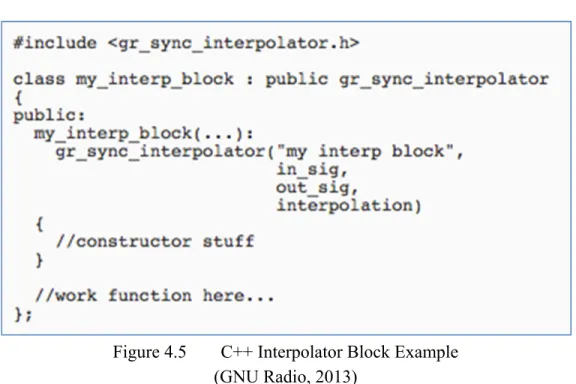
Figure 4.5 C++ Interpolator Block Example ...44
Figure 4.6 Decimator, Interpolator and Filter Implementation ...45
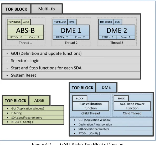
Figure 4.7 GNU Radio Top Blocks Division ...47
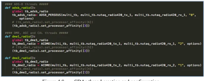
Figure 4.8 SDAs thread creation and configuration ...48
Figure 4.9 Radio Selector Implementation ...50
Figure 4.10 RTDEx src Select 4 ...51
Figure 4.11 RTDEx src Select 1 ...52
Figure 4.12 DME characteristic pulse (Mode X) ...53
Figure 4.13 Received Power & AGC for Radio 1 ...54
Figure 4.14 AGC’s Peak Power Calculation in Simulink ...56
Figure 4.15 System Selector Probes for Simulation ...57
Figure 4.16 Radio 1 Reference-In Connected to Radio 2 Reference-Out ...58
Figure 4.17 RTDEx Stability Measurements Setup ...59
Figure 4.18 RTDEx instability measurement @ 10MSPs –...60
Figure 4.19 FPGA’s resources utilization ...61
XVI
Figure 4.21 Full System Implementation in the FPGA ...63
Figure 5.1 SDR´s Control Window ...66
Figure 5.2 DME specific application window ...67
Figure 5.3 ADS-B specific Application window ...68
Figure 6.1 SDR Control Window in Operation ...71
Figure 6.2 Multi-SDA System Operation ...72
Figure 6.3 Two DME SDAs in Operation ...73
Figure 6.4 Functional SDAs setup ...74
Figure 6.5 Functional tests equipment setup ...74
Figure 6.6 Two DME SDAs tuned to the same ground station ...75
Figure 6.7 Measured Cores Mean Load ...77
Figure 6.8 Python Threads Tree ...78
Figure 6.9 IFR 6000 DME SDA test ...79
Figure 0.1 PicoSDR BIOS Configuration ...88
LIST OF ABREVIATIONS
ACARS Aircraft Communications Addressing and Reporting System ADS-B Automatic Dependent Surveillance-Broadcast
ATC Air Traffic Control
ADC Analogic to Digital Converter
CPU Central Processing Unit
CRC Cyclic Redundancy Code
CRIAQ Consortium de Recherche et d'Innovation en Aérospatiale du Québec DAC Digital to Analog Converter
DF Downlink Format
DME Distance Measurement Equipment DPSK Differential Phase Shift Keying DSP Digital Signal Processor
FAA Federal Aviation Administration
FMS Flight Management System
FPGA Field Programmable Gate Array GNSS Global Navigation Satellite System GPS Global Positionning System
GRC GNU Radio Companion
GUI Graphical User Interface
ICAO International Civil Aviation Organization OMAP Open Multimedia Application Platform
PAM Pulse Amplitude Modulation
PCIE Peripheral Component Interconnect Express
PI Parity/Identity
PPM Pulse Position Modulation
RF Radio Frequency
RTCA Radio Technical Commission for Aeronautics SDAR Software Defined Avionics Radio
XVIII
SDR Software Defined Radio SNR Signal to Noise Ratio
SPI Special Pulse Identification SSR Secondary Surveillance Radar
SWIG Simplified Wrapper and Interface Generator TACAN Tactical Air Navigation System
TMS Transponder Mode S
UHF Ultra High Frequency
VDL VHF Data Link
VHF Very High Frequency
VOR VHF Omnidirectional Radio Range SWAP Size Weight and Power
INTRODUCTION
The need of the aviation industry for innovative ways of integrating current and future avionics systems while taking into consideration size, weight and power (SWaP) constraints is the key factor that enables this project. The introduction of modern processing units that incorporate Field Programmable Gate Arrays with traditional top of the line microprocessor units offer new opportunities with regards to what can be achieved by tight cooperation of these two systems, suddenly tasks that would seem impossible or very complicated to achieve appear now attainable by performing the proper task division and communication routines between them.
Challenges still remain that will put to the test the existing cooperation schemes between the two processing units with regards of timing and efficiency; systems such as the ones here described have already proved their efficiency in fields such as telecommunications and image processing industries, however not much work has been done in the field of avionic navigation systems.
The benefits of the integration of electronic navigation systems and other avionics are not only the reduction in SWaP but also the potential increase in reliability that entirely programmable systems may bring to scene in terms of configurable redundancy and by homogenizing the hardware building blocks of future avionics systems.
This project consists of the definition, design and implementation of a reusable architecture that results solid enough to incorporate modular applications, which shall be able to be loaded and unloaded from the system as the requirements of the mission change. A prototype including a graphical user interface needs to be developed in order to interact with more than one system at a time. It will be showcased as a proof of concept and prepared to perform flight-tests in a real life scenario, the information and results collected will be made available for improvements and future research on the subject. The architecture will also take into
2
account that it will be used for research and development, so it must allow to a group of students to perform their work in a jointly but asynchronous way.
In order to achieve the desired result, a definition of tasks was carefully planned and executed in an orderly way, the work here presented is composed of 6 chapters; the first one introduces the project, its scope, challenges and objectives. Chapter 2 presents the current trends of research in topics related to the one studied by this project, Chapter 3 is an analysis of the scenarios that were considered for the development of the presented architecture and provides the reader with an analysis of such scenarios. Chapter 4 features the resulting architecture and explains the way in which it was implemented. Chapter 5 incorporates the GUI developed for this project, which results crucial for the system´s multi-application operation; finally Chapter 6 covers the system’s operation and its achieved performance.
CHAPTER 1
PROJECT PRESENTATION
1.1 Context Overview
The work presented in this document was developed at LASSENA (Laboratoire des technologies Spatiales, Systemes Embarques, Navigation et Avionique). Because of this, the entire research process is centered on avionics navigation systems and navigation environment.
Even when the technologies used and/or developed in this project could be analyzed from a more general point of view, the avionics and navigation systems approach is always privileged and their analysis is performed from that perspective, the goal of the project was to find and develop means of integrating the different avionics systems that LASSENA had developed into a scalable platform that allowed for future expandability and the aggregation of new systems as they are developed at the laboratory in future projects.
1.2 Research Problematic
The number of avionics systems required by regulation on civilian and commercial aircrafts has been rising steadily since 1950, when the term was coined (Collinson R. , Introduction to Avionics Systems, 2011), and it is only expected to grow in the forthcoming years as the amount and complexity of airborne systems increases.
Up to this day, each time that a new communication technology has been introduced to the navigation environment, the formula has been usually to add new equipment, which requires more space in the already space-restricted avionics systems installation in aircraft cabins. “Equipment is usually at the duplex level of redundancy, for the case of modern airliners
4
VHF radios are at a triplex level of redundancy” (Collinson R. , Introduction to Avionics Systems, 2011) with each device making use of its specific radio and antenna pair.
This is only understandable given the required level of security and integrity at which the aerospace industry operates and due to the considerable complexity of each modern communication device that needs to be installed into an aircraft.
The advent of modern Field Gate Programmable Arrays (FPGA)-Microprocessor cooperative embedded systems gives us a new opportunity to test the extent to which is currently possible to integrate two or more different airborne communication systems into a single generic reprogrammable universal communication device. The following paragraphs introduce the various motivations that enable this research.
1.3 Motivation and Objectives
The presence of multiple burdensome radio communication devices in airplanes is a strong argument to develop an integration architecture that reduces the excessive infrastructure and replaces it by a more flexible Software Defined Radios (SDR) based on shared and reconfigurable hardware.
This project will explore the creation of a standard integration platform that permits the reutilization of hardware components by means of in site re-configurability, providing multiple simultaneous radio operation in order to accommodate future software defined functionalities.
The project’s main objective is to serve as a proof of concept by demonstrating the integration of three independent avionics subsystems such as: TMS (Transponder Mode S), ADS-B (Automatic Dependent Surveillance-Broadcast) and DME (Distance Measurement Equipment) into a state-of-the-art prototyping Software Defined Radio platform. To achieve this objective, a highly optimized tight integration between software and FPGA bitstream
5
image will be designed and implemented to allow the greatest possible extent of cooperation between the FPGA and i7 processing units in such a way that concurrent operation of all the three systems is attained.
As mentioned in (LASSENA, 2013) the successful implementation of the work previously described will enable for future research areas such as:
- The development of a test bench for avionics communication systems and performance analysis, which permits achieving a high level of reliability for the SDR communication system’s applications;
- The analysis and study of the integration architecture of multiple individual SDA modules into a single hardware;
- The leverage of significant interoperability issues (partial reconfiguration, on-the-fly reconfiguration, resource sharing, etc.);
- Performance analysis of the integrated avionic SDR in real-life scenarios.
The system developed in this project was conceived in several incremental steps, the SDAs previously developed at LASSENA went through a revision and test phase to assess the possible ways of integration into a single scalable platform. After being separately evaluated into their original development platform (Zepto, USRP) they were ported to the defined integration system and their capabilities were re-assessed accordingly.
It was until this point when an integration effort was started. Tests in the laboratory were performed in an incremental way until the full system was completed. A full testing documentation package (available in Annexes I to V) was prepared for the selected prototypes to be tested in flight; before the execution of the flight tests, ground tests were also performed in the plane and in-ramp where applicable.
6
1.3.1 AVIO-505 Project
The AVIO-505 project is an industry-academia collaborative research effort between LASSENA and the Consortium de Recherche et d'Innovation en Aérospatiale du Québec (CRIAQ) the work developed during this master’s project is framed as part of the AVIO-505 project, which has a much broader scope. A brief description of the project is presented:
AVIO-505 project aims to establish new design methods and digital signal processing techniques for robust and efficient universal navigation and communication equipment in the fields of aeronautics and aerospace. The project anticipates the integration of multiple navigation and communication systems in a single hardware element minimizing connectors, antennas, cable length, electromagnetic interference (EMI) and system footprint. The project’s goal is “to digitize the radiofrequency (RF) signal in proximity to the antenna and to transmit the baseband signal to a generic radio for further digital signal processing” The proof-of-concept demonstrator will be evaluated in-laboratory and in-flight using simulation equipment and a flight test platform under real operating conditions in order to characterize protocols and system performance. “The developed technologies will also be applicable to ground or airborne infrastructure.” (LASSENA, 2013).
The context overview and motivations that enable this research have been briefly introduced by these first pages. The following chapter presents a literature review, which covers the development of avionics systems and the historical integration efforts that have been introduced since their appearance in the aviation industry.
CHAPTER 2
LITERATURE REVIEW
2.1 Reconfigurable Avionics Systems
Military investment in modular radio components during the 90’s (Upmat, 1995) enabled technologies that permitted to bring most of the signal processing components of radio system into a computer (Bivona, 2009). These efforts pioneered the study of Software Defined Radio Systems, later, by the beginning of 2000 efforts such as (Eyermann, 1999) continued advancing the research in avionics related fields. Finally the Spectrumware project served as a root for two different SDR development branches, Vanu Radio (J. Chapin, 2002) and GNU Radio.
For the last 30 years approaches that aim at facilitating the integration of avionics systems have been under development; the two primary widely accepted guidelines for avionics architectures in the US are: an Open Systems Architecture (OSA) directive from the Department of Defense (DoD) and an Integrated Modular Avionics (IMA) standards guideline from DO-297 (Gask, 2015).
There is a recent interest from avionics manufacturers to develop upcoming avionics systems able to perform expected growing software volume and capability. This need is a challenging one as software exhibits some difficulties to meet increasingly stringent performance requirements while keeping other requirements in terms of reliability, continuity, availability and integrity. In (Strunk, Knight, & Aiello, 2004), a flexible architecture based on distribution of function and assured reconfiguration that can react to failures in both hardware and software is introduced. The authors manage to architecture reconfigurable software satisfying safety properties and enhancing analysis capabilities for critical safety properties and reduce certification costs for much of the system.
8
In (Hodson, 2007) a reconfigurable avionics for exploration is fully described. The goal of avionics in exploration is to provide scalable interoperable avionics for a wide class of space exploration missions to optimally satisfy or outperform the highly demanding specifications while at the same time minimizing the cost of development, deployment, and maintenance of avionics in the space vehicles. This is added to the fact that space missions develop for several years during which the needs evolve at a high pace while the hardware equipment cannot be updated after the mission has started. It is for this reason that reconfigurable software avionics play a fundamental role, since software is the only component of the avionics that can be updated to meet the new requirements.
An interesting approach to reconfiguration, software defined avionics is presented in (Suo, An, & Jihong Zhu, 2011). As the main concern of SDA relies on reliability, this work explores a new technique to realize fault-tolerance and respond to changes in external environment. The technique is applied to the design of Integrated Modular Avionics. The main novelty of the work refers to their innovative approach to address the safety problem of Avionics reconfiguration. Traditional analysis approaches mainly focus on single component failure. Therefore, they might underestimate the influence of a design flaw. On the contrary, the authors propose the use of System-Theoretic Process Analysis (STPA) to carry out a hazard analysis. They focus on the interaction between human operator and equipment, and define two criteria to decide the level of autonomy: the Failure Degree, and the Time budget. System dynamics are applied to analyze and model human factors such as mental workload, situation awareness and complacency.
Integrated modular avionics face several challenges in order to enable their operation in aerospace systems (Gask, 2015). Firstly, multi-core systems do not currently meet the aviation standards in terms of reliability and integrity. It is critical to leverage chips with many cores (some of which are heterogeneous) for affordability and size, weight, and power (SWAP) constraints. This cannot be achieved without the insertion of new and refined software standards for improved reuse. Therefore software-defined avionics require
9
necessarily a new mind-set in the regulatory agencies only to be achieved after SDRs have proven its reliability for the aviation sector. In addition, the unification of mixed networking technologies is important to support bandwidth and connectivity flexibility. For instance, the use of fiber optics can improve significantly both the weight and the available throughput required by these systems. Therefore, signals do not necessarily need to be processed at the antenna and distributed avionics systems can be deployed while decreasing dramatically the weight of the cabling. Software defined avionics can also provide greater autonomy and improved safety and availability since they can run self-check routines and self-diagnose operational problems. Trying to meet this objective with conventional hardware-based systems is, nowadays, beyond the state-of-the-art technology.
We can notice that two variants of the SDR implementation exist, one in which most of the processing takes place on the FPGA, and the computer only executes control and display tasks and another in which the signal processing tasks are carried out by a computer where we can find a general purpose processor. In this latter case, the FPGA only performs basic signal processing such as filtering and down sampling (Debatty, 2010). In the last years a notorious increase in Lines of Code (LOC) has been observed in avionics systems, where systems have moved from 100K LOC to 400K LOC. It is expected that in the next decades the complexity will continue increasing exponentially. There has been as well a generalized focus in Size, Weight and Power reduction for avionics systems development (Gask, 2015) to the extent of prototyping entire avionics systems in SoC (System on a Chip); this approach has found limitations for certification of safety-critical embedded systems (El Salloum, 2013).
Future avionics systems will certainly base their hardware in multicore general-purpose processor because of their reduced cost and high performance. According to (Gask, 2015), it is expected that by 2016-2018, there will be on-chip multicore processors with 16 or more cores on each die integrated with on-chip transformational multi-Teraflop General Purpose Graphics Processing Units (GPGPUs). The aviation sector cannot disregard the
10
computational power of this equipment and will definitely have to adapt its mainstream to the use of these devices from which software defined avionics will be their major beneficiary.
2.2 "SDR", "SDA" and "SDAR"
During the next pages the acronyms SDR, SDA and SDAR are frequently used throughout the text; it is important though to clearly identify what is referred to when making use of these terms. For this reason they are defined and put into context for the scope of this project:
Software Defined Radio (SDR): According to ITU-2009 definition, “a radio transmitter
and/or receiver employing a technology that allows the RF operating parameters including, but not limited to, frequency range, modulation type, or output power to be set or altered by software, excluding changes to operating parameters which occur during the normal pre-installed and predetermined operation of a radio according to a system specification or standard.” (International Telecomunication Union (ITU), 2009).
Software Defined Application (SDA): A set of software instructions or computer program
that interacts with the SDR components either to obtain/send information through them or to perform its configuration with the final goal of replicating specific equipment functionality.
Software Defined Avionics Radio (SDAR): It consists of the application of the SDR
concept to the field of avionics. An SDAR can optimally perform any avionics application, including but not limited to communications, navigation and surveillance systems. SDARs promise to eliminate unnecessary redundancies in the avionics equipment and therefore minimize the weight and fuel consumption of aircraft operations, which in turn translates to a greener aviation.
11
2.3 Selected Avionic Systems for the Integrated Architecture
As briefly mentioned in the previous chapter, this Master’s research project has been developed within the pale of collaborative research and development project AVIO-505. Therefore, its main objective is given by the definition of the AVIO-505 project, which aims at demonstrating through a proof-of-concept prototype the feasibility of Software Defined Avionics Radio (SDAR). This prototype must perform a functionality of each of the three main functions required by aviation, i.e. Communications, Navigation, and Surveillance. For the communications systems, a wideband radio system was selected in addition to satellite communications equipment. As regards the surveillance systems, the nineties-developed system transponder mode-S (TMS) and the NextGen keystone system named Automatic Dependent Surveillance-Broadcast (ADS-B) were selected. Finally, for the last function, which is navigation, the selected system is the distance measuring equipment (DME). This project will integrate these three avionic systems into a single piece of hardware; contributing in this way to the simplification of the intricate avionics systems interconnection that exists nowadays. The following sections are devoted to briefly describing the particularities of each of the selected systems:
2.3.1 Distance Measuring Equipment
The Distance Measuring Equipment is an avionics navigation equipment that measures the geometrical distance between the aircraft and a ground station (Collinson R. P., 2013). As the location of the ground station antenna is known, this information can be used in combination with other in order to determine the aircraft position. From one DME measurement, the aircraft can be located within a sphere around the ground station. Combined with another DME measurement, or VOR, the uncertainty can be reduced to a circumference (half a circumference when the VOR and DME stations are collocated, which is usually the case) normal to the ground plane. Thus, only the altitude is needed in order to determine the aircraft position. The airborne DME equipment operates very similarly to radar equipment. A
12
pair of short pulses is omnidirectionally transmitted and received by the ground station. After introducing a known deterministic delay, the ground station retransmits this pair of pulses at a different frequency that determines the full-duplex channel. The ground station acts, thus, as a transponder. Finally, the reply from the ground is received at the aircraft and the measured is between the interrogation and the reply is measured, from which the distance or slant range is determined. As it can be seen, the DME is similar to a secondary radar, with two differences, the radar is not on the ground but airborne, since the antenna used is not a scanning one but omnidirectional, no angular information can be extracted from the measurement. The interrogation is transmitted at frequencies within the range 1025MHz to 1150MHz, while the replies can be received from 960 MHz to 1215 MHz. As it can be seen, both frequency overlay and proper channel frequency planning must be done in order to prevent self-interference. Another source of intra-system interference is produced by multiple aircraft interrogating the same ground station, which can only operate in one frequency channel. The medium access is done by collision using low duty-cycles and using a randomly generated interrogation pattern. Therefore, only replies following the same random pattern unique for every aircraft are identified as own. The use of different transmission schemes called mode X and mode Y doubles the number of channels. (LASSENA, 2013) (Spitzer, 2014) (Collinson R. , Introduction to Avionics Systems, 2011).
2.3.2 Automatic Dependent Surveillance – Broadcast
The Automatic Dependent Surveillance – Broadcast is the keystone of the NextGen and SESAR programs at the USA and the European Union, respectively, both programs being harmonized by ICAO. ADS-B is the modernization of the Air Traffic Management (ATM) Surveillance system currently based on the ATCRBS and the Transponder Mode-S briefly described below (Collinson R. P., 2013). When both are installed in an aircraft, the TMS and ADS-B equipment must be part of a single piece of hardware equipment (RTCA Special Committee 170, 1992). Through ADS-B, all the air traffic participants (not only aircraft, but also ground vehicles, UAS, parachutes, obstacles, etc.) broadcast their 3D position, latitude,
13
longitude and height to the rest of participants. The system is therefore “dependent” on an additional navigation system providing it with this 3D position. Usually, the navigation system used is GPS, which dramatically diminishes the uncertainty of the aircraft position, from hundreds of meters achieved by secondary radar-based traffic control to few meters provided by the GPS system, especially in those areas where an augmentation system such as WAAS (Wide Area Augmentation System) or EGNOS (European Geostationary Navigation Overlay Service) has been approved for its use in aviation. This will enable separation limits reduction between aircraft in safe conditions, which directly translates to an increased capacity (in flights per hour) of the air transportation system. The ADSB system operates at frequency 1090 MHz, (the same as TMS) which is why the systems need to be synchronized when collocated. Traffic control can therefore be automated, although such automation is not part of ADS-B. Currently, computers on the ground integrate all the information and provide controllers with timely warnings of potential problems. (LASSENA, 2013) In the USA, the ADS-B is also enabled to operate at the Universal Access Transceiver (UAT) frequency 978 MHz.
2.3.3 Transponder Mode-S
The Mode-S (S for Select) of the secondary surveillance radar (SSR) was designed as an evolutionary addition to the Air Traffic Control Radar Beacon System (ATCRBS) to provide the enhanced surveillance and communication capability required for Air Traffic Control (ATC) automation; the spec was delivered to FAA in 1975 (Freeman, 1995) (Collinson R. P., 2013). However, the promised automation has not been yet achieved, which is one of the main motivations of ADS-B. A transponder Mode S performs all the functions of Mode A (squawk code only) and C (squawk, pressure and altitude) transponders and has data link capability. This capability is the one exploited by ADS-B for its operation, although the use of software defined avionic radios would have enabled much more flexible (and long-term) solutions. Some of the TMS specific advantages over Modes A and C are:
14
• Since aircraft are selective interrogated, as opposed to Modes A and C, the channel is less saturated which increases the capacity of the system. However, it is expected that modern ADS-B can produce an increase in the 1090 MHz channel saturation again, going back to the times of the modes A and C transponders;
• The accuracy of TMS is improved when compared to Modes A and C, thanks to the use of monopulse techniques and increased bandwidth. However, ADS-B (when based on GPS) overpasses by far this improvement and makes TMS obsolete as a source of traffic positioning information;
• High degree of data integrity in ground-to-air, air-to-ground and air-to-air data link, as CRC codes are used with a probability of an undetected bit error lower than 10-7. (RTCA Special Committee 209, 2011);
• In TCAS equipped aircraft, the TCAS transmits coordination/interrogations to the other aircraft via the Mode S link in order to ensure the selection of complementary Resolution Advisories. (LASSENA, 2013).
2.3.4 The Wide Band Radio communications systems
Avionic communications systems, such as ACARS, VDL (VHF Digital Link), or voice communications, use little bandwidth and represent no challenge for the AVIO-505 project. Similar considerations apply to aircraft communications through satellites, currently using mainly the L-band frequencies. On the other hand, Ku and Ka-band satellite communications systems definitely pose a meritorious challenge for the AVIO-505 project but the development of a proof-of-concept-prototype would suppose a prohibitive increase in the project’s budget. As an alternative, a custom communications system was selected and specified. Among these specifications, one can find high throughput (4 Mbps minimum) and
15
increased robustness thanks to the use of Adaptive Modulation and Coding (ACM), which is a technique widely spread in satellite communications.
2.4 Software Integration Tools
An overview of the two main tools used for this project´s development is presented here; the intention is to take the reader into context not to have a detailed explanation of them. For further information regarding these tools refer to their original sources in the reference section.
2.4.1 GNU Radio
GNU Radio is a free Software Development Toolkit (SDK) that has greatly accelerated the development of avionics systems in the AVIO-505 project. This SDK provides the avionics engineer with a set of signal processing libraries including many of the most common signal processing tasks such as filtering of phase lock loops. It also provides the capability of real-time scheduling and a very useful feature for this master project which is the capability of dynamic core affinity for the individual tasks during runtime. Another important feature is that it provides compatibility with a number of software radios using readily available, low-cost external RF hardware and commodity processors. Moreover, SDR manufactures are not unaware of the popularity of GNU Radio in the SDR developer community and very often provide a GNU Radio plugin to interface with their hardware. Such is the case with at least the following three Nutaq devices: ZeptoSDR, PicoSDR and PicoDigitizer. GNU Radio is widely used in hobbyist, academic and commercial environments to support wireless communications research as well as to implement real-world radio systems.
GNU Radio applications are primarily written using the Python programming language. However, there is a complementary python application, GNU Radio Companion (GRC), which provides the user with a developing environment similar to Simulink’s environment.
16
All the performance-critical signal processing path is implemented in C++. GRC allows the C++ blocks to be interconnected in a graphical interface and it is the tool the one that generates proper Python code for the engineer. (GNU Radio, 2015)
However, GRC offers very limited capabilities with regards to this master’s project. First, many of the avionic systems performs tasks that go much beyond merely signal processing. All these tasks need therefore to be implemented in python, which is not allowed by GRC. Second, other tasks related to the SDARs and the reconfigurability aspect can only be implemented outside GRC, specifically dynamic core reassignment, dynamic radio reconfiguration, inter-systems interaction, etc.
2.4.2 Xilinx System Generator and Nutaq’s Model Based Design Kit
Most of the FPGA programming has been done at the highest possible level of abstraction by means of Nutaq’s Model Based Design Kit (MBDK) for Xilinx’s System Generator (Xilinx, 2015). Since one of the main objectives of the AVIO-505 project is to prove that avionics systems can be designed and implemented exclusively in the software domain, it did not make sense to use low-level tools to program them, in which case, all of the benefits of the SDAR during the design and development stages would have just vanished. Nutaq’s MBDK is a plugin thought for its use along with Xilinx’s System Generator. The kit allows the user to program the FPGA just by interconnecting elementary (and not so elementary, e.g., FIR filters or DDS’s) signal processing blocks that perform the desired tasks for the FPGA. It is a system-level modeling tool that facilitates FPGA hardware design. It extends Simulink in many ways to provide a modeling environment that is well suited to hardware design. This provides the engineer with high-level abstractions that can be automatically compiled into an FPGA. With these tools, the design phase of the digital signal processing performed by FPGA devices can be carried out at a higher level, which results in reduced development time. Although not required in this project (which was intended), the tool also provides access to underlying FPGA resources through low-level abstractions.
17
2.5 The Integration Platform
A state of the art SDR system was provided by Nutaq®, which is one of the strategic partners of the AVIO-505 project, the SDR system comprises a fully integrated solution for embedded signal processing. The following section introduces the system by depicting its building blocks and better explaining its main capabilities.
2.5.1 Nutaq’s Software Defined Radio (PicoSDR2x2-E)
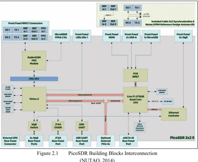
A top-view diagram of NUTAQ´s PicoSDR2x2-E, showing its building blocks and the way in which they interconnect is presented in Figure 2.1. Section 2.5.1.1 outbreaks more in depth each of the relevant system´s hardware components; the hardware component’s limitations are consequently addressed in section 3.3, where an overall consideration of the system´s capabilities is performed.
18
Figure 2.1 PicoSDR Building Blocks Interconnection (NUTAQ, 2014)
Internal Hardware Components and Specifications 2.5.1.1
An overview of the crucial PicoSDR hardware components used during the development of this project is presented in the following sections. The overview permits the reader to have a better idea of the general system´s capabilities. The PicoSDR components, which are essential for the project development are:
1. The radio card (Radio 420M FMC), 2. FPGA’s Mezzanine card (Perseus 6010), 3. FPGA type and family (Xilinx Virtex 6), 4. The embedded host system (SAMC-514).
19
Radio 420M FMC 2.5.1.2
The Radio420X FPGA Mezzanine Card (FMC) is a powerful SDR RF transceiver module designed around the Lime Microsystems LMS6002D RF transceiver IC, it is able to operate in multiple modes, multiple standards and multiple bands, supporting broadband coverage, TDD (Time Division Duplex) and FDD (Frequency Division Duplex) all of it while maintaining full duplex operation. Its selectable transceiver’s bandwidth covers from 1.5 to 28 MHz, which makes it suitable for a large number applications (both broadband and narrowband). It incorporates multiple references and synchronization modes that allow the Radio420X to be appropriate for multimode SDR applications. As mentioned in (NUTAQ, 2014), other suitable applications include:
1. MIMO systems, 2. Cognitive radios, 3. LTE, WiMAX, 4. White space, 5. Wi-Fi, 6. GSM, 7. WCDMA,
8. Signal intelligence (SIGINT).
Perseus 6010 2.5.1.3
The Perseus 6010X is an advanced mezzanine card (AMC or AdvancedMC) designed by Lyrtech®. It is designed around the Xilinx Virtex-6 FPGA, allowing great flexibility to select between different Virtex 6 parts for the boardand up to 4 GB of external memory. It benefits from multiple high-pin-count, modular, add-on FMC-based I/O cards. “The Perseus is intended for high-performance, high-bandwidth, low-latency processing applications”
20
(NUTAQ, 2014). The card is fully supported by Nutaq’s advanced software development tools, which aids with design when aiming to reduce “size, complexity, risks and costs associated to leading- edge telecommunications, networking, industrial, defense and medical applications” (NUTAQ, 2014).
Nutaq’s Real Time Data Exchange (RTDEx) 2.5.1.4
RTDEx is an FPGA soft-core developed by NUTAQ, which “allows high-speed transfers of data between a host PC and an FPGA device, or between FPGA devices. The RTDEx uses the Gigabit Ethernet-base channel or PCI Express Gen1 4x. The PCI Express is only usable with the Linux operating system on an embedded AMC processor” (NUTAQ, 2014). Being the main communication protocol used to transfer data between the host system and the FPGA (the other being custom register direct access), it resulted a crucial tool for the integration of the system. Sections 4.1.1, 4.2.3.2, 4.2.3.3 and 4.2.3.6.3 contain further information on this protocol and its utilization in the project; in the same way Appendix VI is entirely dedicated to the tests performed for the protocol characterization.
Xilinx Virtex 6 2.5.1.5
FPGA family developed by Xilinx® “The Virtex-6 family is built on a 40 nm process for compute-intensive electronic systems” (PR Newswire, 2009).
SAMC-514 2.5.1.6
The SAMC-514 processor module is an AMC form factor unit developed by the Russian company Scan Engineering Telecom (“CJSC” by its Russian Accronym). The module is based on a high-performance Intel Core i7 (Sandy Bridge) processor; the SAMC-514 unit combines a wide range of inter-module interfaces with large amounts of RAM. (Setdsp,
21
2014).
The literature review presented in this chapter covers the avionics systems integration schemes and its development from the early 90´s to the current day. It introduces the reader to the more recurrent terms used throgouth the work and defines them in the cases where the terms are not taken from previous works. A brief presentation of the tools in which the integration architecture, product of this work, is to be integrated and presents in the same way the more important system platform components’ specifications and its capabilities.
CHAPTER 3
ARCHITECTURE ANALYSIS
In this chapter, the hardware capabilities of the integration platform presented in Section 2.5 are taken into consideration for the first time to explore possible solutions to the given problem. The system’s required tasks are defined from a top level perspective and two different approaches for the integration of the avionics applications addressed in Chapter 2 are presented.
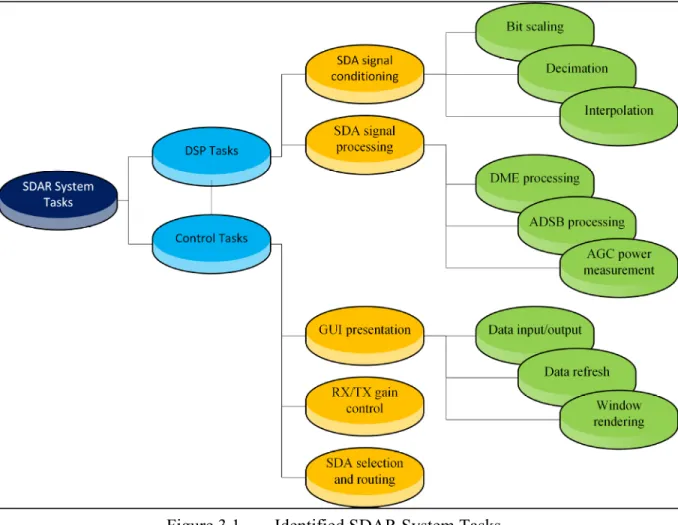
3.1 System’s tasks identification
The system’s processing functionality can be divided in two main functional areas: 1. Digital Signal Processing (DSP) tasks,
2. Control tasks.
These two areas can be divided further into more concise functions that will be later assigned to one of the two processing units found in the PicoSDR2x2-E:
1. i7 (CPU),
2. Virtex-6 (FPGA).
Table 3.2 presents the system’s tasks organized by functional area and shows which of the sub-systems in the PicoSDR are capable of executing such tasks.
24
Table 3.1 Processing tasks and available system’s capability
Processing tasks and. available sub-system’s capability
System’s Tasks System’s Capability
i7 Virtex-6
(CPU) (FPGA)
DSP tasks
SDA Incoming signal
conditioning ✔ ✔
SDA Signal processing ✔ ✔
SDA Outgoing signal
Conditioning ✔ ✔
Control tasks
Graphical user interface
(GUI) presentation ✔
SDA selection and routing ✔ ✔
Rx gain control ✔ ✔
Tx gain control ✔ ✔
As seen in Table 3.1 just the GUI presentation is restricted to be executed by the CPU. For all of the other tasks, decisions have to be taken regarding their assignation to at least one of the processing sub-systems. It is important to mention that for some of the tasks, processing can occur in both of the sub-systems at different stages of the signal processing, so the assignation of one of them to a processing unit does not excludes it from being assigned to the other one as well.
25
Figure 3.1 Identified SDAR System Tasks
3.2 Integration Architecture Approaches
The model considers the seamless integration of SDAs systems whose processing logic may come from three different design approaches based on the processing tasks that are assigned to each of the processing units of the PicoSDR:
1. [TYPE I] -PURE CPU SDA: Where the FPGA is used in a pass-through configuration and the processing happens almost entirely at the CPU level;
2. [TYPE II] -HYBRID CPU-FPGA SDA: Where the logic is balanced between the FPGA signal processing capabilities and the CPU;
26
3. [TYPE III] -PURE FPGA SDA: Where the whole SDA is hardware defined and just the user interface information is sent to the CPU for presentation and user interaction1.
The architecture receives baseband inputs and it outputs the processed stream through RTDEx-Ethernet interface or directly through one of the peripherals if the entire signal processing is performed inside the FPGA. The architecture is planned to be compatible with as many pure FPGA SDA as the FPGA fabric can fit in. For the applications that make use of RTDEx (TYPE I and TYPE II SDAs), the limit is imposed either by the maximum number of RTDEx channels that can be simultaneously open or by RTDEx’s upper throughput limit (whichever is reached first) 2.
3.2.1 Full FPGA Solution
It is possible to define the entire SDAs’ logic by making use of a combination of System Generator® blocks and hand written/modified VHDL code. Unsurprisingly this approach requires depth knowledge of VHDL and certain characteristics of the defined applications would be tied to the specific model and limitations of the FPGA for which the design is originally made. This would also result in the application with the highest overall performance; since there is no computer processor involved in the flow path of the signal, the hardware-described implementation would result in deterministic latency of the system. The only limit to this approach would be the space (in logic gates) provided by the specific FPGA model in which the SDAs would be defined.
1From this point on, when referring to the SDAR system classification, the labels: TYPE I, TYPE II and TYPE III are used.
2 RTDEx nominal upper-limit is 1 Gbps, however as shown in APPENDIX VI by the tests performed in the lab,
27
Since each system to be defined needs to be hardware defined from scratch and very low design reusability can be implemented, this approach would also result in the longest development time when compared to the other options evaluated here.
3.2.2 Full CPU-Based Solution
By using the FPGA in bypass mode (i.e., IQ samples from the receiver’s ADC are made available at the CPU, and IQ samples from the CPU are directly pushed to the transmitter’s DACs), a fully functional SDA can be designed in GNU Radio. As a matter of fact, this was exactly the approach taken in LASSENA to prototype and build other functional SDA systems making exclusive use of GNU Radio. These are SDAs where the CPU of the host system performs the entire signal processing. This approach has shown to provide a lot of flexibility when compared to solutions based exclusively on FGPA’s fabric impacting also positively the development time of the system as a whole. An additional advantage to the faster development time is that there is no need to deal with hardware (timing, latencies, etc.) issues. The design task is also enormously facilitated by the set of libraries provided by GNU Radio SDK.
3.3 Hardware Limitations
Once that Nutaq’s PicoSDR2x2-E was selected as the project’s development platform; an analysis of the hardware components that are part of the unit is needed to understand the limitations and capabilities of the system. Such an analysis is presented in the following sections.
3.3.1 Radio 420M FMC
The Radio420M FPGA Mezzanine Card (FMC) is based on the lime LMS6002D RF transceiver IC, which supports broadband coverage, as well as TDD (Time Division Duplex)
28
and FDD (Frequency Division Duplex) full duplex modes of operation (NUTAQ, 2014) The RF transceiver instantaneous bandwidth covers from 1.5 to 28 MHz. which can be tuned within the frequency range from 300 MHz to 3.8 GHz. Two LMS6002D are included in the Radio420M FMC, which provides it with 2×2 MIMO operation. (Jalloul, 2014) Therefore, the system is limited to two systems working simultaneously, as only two transceivers are physically included in the platform front-end.
3.3.2 Perseus 6010
The Perseus AMC connects to a computing system a.k.a. ‘Host’ to exchange information and take advantage of its processing power. Just two interfacing options are provided to interconnect the ‘Host’ and Perseus systems:
1. 4xPCIe, which provides a dedicated connection to the embedded SAMC-514 system (‘Host’) in the default configuration;
2. 1x GigE, which allows a connection to an external ‘Host’.
Note: Additionally the PCIe interface can be also used to interface to an external ‘Host’ running a Linux system but extra equipment is required (NUTAQ, 2014).
Since Perseus 6010 is built around the Virtex 6 FPGA family, it supports only the 4 following parts:
5. 6010: LX240T, 6. 6011: LX550T, 7. 6012: SX315T, 8. 6013: SX475T.
The newest Virtex 7 family parts and development tools like the Xilinx ‘Vivado suite’ are not supported. This means that the system is limited to use the older Xilinx ‘ISE Design
29
Suite’ which impedes the user to acces the latest development capabilities introduced by Xilinx.
Other important limitations addressed in (NUTAQ, 2015), include: 1. Up to 4 GB, 64-bit DDR3 SDRAM SODIMM;
2. 64MB NOR flash memory (16 bits) for FPGA images, MicroBlaze boot code and user code;
3. Mid-size AMC (allows component heights maxed at 11.65 to 14.01 mm); 4. Two GigE ports;
5. Serial RX/TX—Mini-B USB (UART).
3.3.3 SAMC-514
The SAMC-514 comes with an Intel 4C i7 processor, clocked at 2.1GHz, a 64GB SSD SATA drive and 8GB DDR2 SDRAM SODIMM. These are the three main factors that impact the overall system’s response and set the limit to the applications that can be executed in it (NUTAQ, 2014).
All of the limitations here presented were assessed when designing the system´s behavior and defining its expected capabilities; their specifications give us a first glance of the maximum performance that can be attained by the system as a whole. The following section proposes an SDAR architecture based on the hardware presented in this chapter.
CHAPTER 4
THE PROPOSED SDAR ARCHITECTURE
Taking into account the considerations presented on the previous chapter, a suitable architecture needed to be implemented. After analyzing both of the solutions proposed in Chapter 2, a combined FPGA/CPU solution, was developed and implemented on the PicoSDR; the result is a design that takes the best from each of the two alternatives presented and mixes them in a functional way. This chapter explains the details of the implemented solution.
4.1 SDAR Architecture Details
To make the integration scheme as comprehensive as possible, instead of describing specific hardware into the FPGA for each of the desired SDAs in a given configuration, a cooperative scheme comprising the CPU and FPGA communicating through RTDEx has been sought. In such design data enters the FPGA from Radio420M’s ADCs and is routed to the current user-selected channel(s) through RTDEx. Once in the CPU side, GNU Radio will take care of processing the data and will output it back to the RTDEx bus where the FPGA will make use of a series of demux blocks to route the signal to the right radio output. A conceptual representation of the system is presented in Figure 4.1.
32
33
To achieve this tight cooperation between CPU and FPGA, and to allow the concurrent operation of SDA types I, II and III, Nutaq’s 1Gbps-Ethernet-RTDEx interface is used. The ethernet implementation of Nutaq´s RTDEx was selected over its PCI version because the PCIe interface requires costly additional interconnection hardware to be used with an external (non-embedded) host CPU system. This hardware needs to be installed in each host system to be used for development. Therefore, to facilitate the development of the different SDAR modules by a team composed of several students, it is highly advisable that a common RTDEx interface is used in the design regardless whether the system operates the embedded CPU or an external host. This can only be achieved by using the Ethernet interface.
Using the PicoSDR2x2-E, there is a maximum of two Radio420 interfaces, which means two independent Tx/Rx transmission paths. To be able to have more than two SDA’s concurrently working in the system, switching and control logic needs to be implemented at both the FPGA and CPU to perform the adequate signal routing to the desired radio interface. Note that only two systems will be operational at a given time due to the radio limitation, but these two systems can be chosen from a set of N systems concurrently running on the embedded CPU.
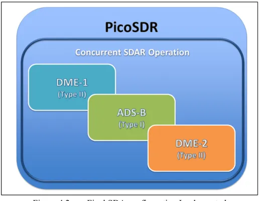
A minimum of three independent SDA’s is needed in the final implementation to proof this project’s concept. The original planning considered a TMS, an ADS-B and a DME system to be integrated together, however due to TMS signal timing constraints explained by (Jalloul, 2014), TMS was identified as a ‘TYPE III’ system and a full redesign was required. Since the redesign of the entire TMS application clearly falls out of the scope of this project, an extra DME system was selected to replace the missing TMS SDA3.
The final SDA configuration is presented in Figure 4.2, it includes one ADS-B and two independent DME systems working concurrently.
34
Figure 4.2 Final SDA configuration Implemented
4.1.1 RTDEx Considerations
To achieve the concurrent operation of the three systems, an exclusive RTDEx channel, out of the eight provided by Nutaq’s implementation, was assigned to each of the three SDA systems to be integrated. This solution allows for up to eight concurrent systems, which is more than required at the current implementation time. In the future this limitation can be overcome by additionally multiplexing more than one system channel through a single RTDEx channel.
ADS-B SDAR executes its entire processing logic in the CPU side of the platform while DME balances its processing logic load between the CPU and FPGA making them TYPE I and TYPE II SDAs respectively, as defined in the introduction of section 4.
Since the required sampling rates of DME and ADSB SDARs are not the same, (1Msps for DME, 4Msps for ADSB) and because Radio420’s sampling frequency cannot be changed
35
dynamically once initialized; both Radio420 devices have to be configured to sample at the highest sampling frequency of the SDAs that were included in the design (4Msps for this case). Adequate decimation, interpolation and filtering have to be implemented in the system to cope for these differences in sampling rates between SDAs; further details are available in section 4.2.1.2.
Based on the fact that RTDEx uses a 1Gbps link, the available data rate was initially assumed to be close to the 888Mbps4 however; the tests performed in Appendix VI show that the actual full throughput provided by the RTDEx medium is 553*2 Mbps.
For the selected configuration (Two DMEs + one ADSB), three concurrent RTDEx channels processing 4MSps each need to be in continuous operation. The whole system throughput is calculated below:
ℎ ℎ ℎ = ∙
ℎ ℎ ℎ = 4 ∙ 32 = 128 ( 4.1 )
ℎ = ℎ ℎ ∙ ℎ
ℎ = 128 ∙ 3 = 384 ( 4.2 )
Which represents 34.71% of the actual RTDEx limit per channel (553Mbps) found by the tests described in Appendix VI.
Additional throughput optimization can be attained by using Time Domain Multiplex (TDM) techniques and suitable interleave of all the three system channels through a single RTDEx channel.
36
4.1.2 Tools for the Implementation
For the first part of the implementation, which is related to the entire processing executed at the CPU level, “GNU Radio” and “Nutaq’s GNU Radio plugin” were the main tools used during this phase. “GNU Radio Companion” was also used to create other prototypes that were lately abstracted to python code and defined exclusively there.
For the FPGA’s logic implementation, System Generator and Simulink were the tools of choice. Combined with Nutaq’s MBDK (Model Based Development Kit), they allowed access to specific PicoSDR peripherals and configuration parameters.
The Nutaq’s CLI (Command Line Interface) was indispensable to perform signal capture at fast rates, when DME signals from the IFR-6000 were captured and stored on PicoSDR’s DDR3 RAM and then replayed in Simulink for offline simulation purposes, more information regarding this data capture and replay is available in section 4.2.3.5.
4.1.3 FPGA/CPU Tasks Separation
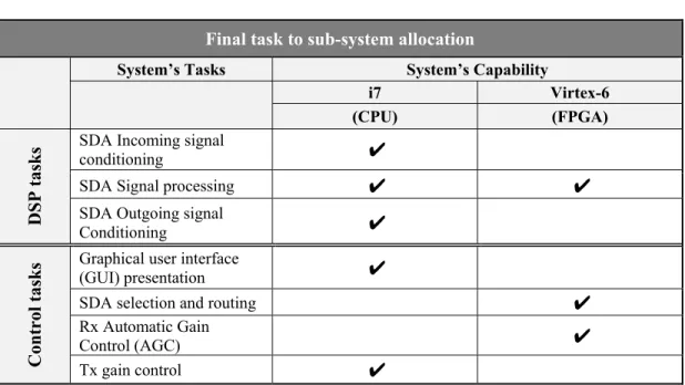
To take full advantage of the processing power offered by the PicoSDR2X2-E, a separation of tasks was carefully planned between the i7 CPU and the Virtex-6 FPGA. The challenge was to maximize CPU’s digital signal processing (DSP) capability with GNU Radio by setting it free from the non-essential DSP tasks required by the system. The resulting task allocation is presented in Table 4.1.
37
Table 4.1 SDAR Final tasks to sub-system allocation
Final task to sub-system allocation
System’s Tasks System’s Capability
i7 Virtex-6
(CPU) (FPGA)
DSP tasks
SDA Incoming signal
conditioning ✔
SDA Signal processing ✔ ✔
SDA Outgoing signal
Conditioning ✔
Control tasks
Graphical user interface
(GUI) presentation ✔
SDA selection and routing ✔
Rx Automatic Gain
Control (AGC) ✔
Tx gain control ✔
It can be observed that for the SDA configuration here presented (exclusive use of Type I and Type II applications), the control-related tasks are assigned to the FPGA while most of the signal processing stays in the CPU side.
It must be noticed than an effort was made to include the signal conditioning logic into the FPGA to free up more CPU resources. Nonetheless a multi-rate RTDEx implementation results out of this scheme and problems with RTDEx latency and sync parameters were observed when trying to concurrently execute systems with different sample rates.5
The three systems send data concurrently to the three open RTDEx channels, which will then be switched to/from the Radio interfaces by the FPGA’s logic upon user request via custom FPGA registers accessible from the Nutaq’s Python API.
5 Decimation and interpolation are performed by GNU Radio’s logic, it is left for future work to incorporate this
signal conditioning at the FPGA level so that just the essential info can be sent to the CPU for processing. See ‘Recommendations’ section.
38
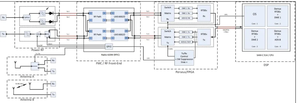
Figure 4.3 presents a simplified block diagram that shows the signal flow in the system. To be able to efficiently switch from a running SDA to another one at runtime, the control logic was implemented at the FPGA level, which allowed us to relief the CPU from the burden of the switching task; this is explained further in section 4.2.3.1.
Figure 4.3 Simplified signal flow Diagram
4.2 Proposed SDAR Implementation
The implementation details are presented in this section; the specific modifications to Nutaq’s libraries as well as the deviations from GNU Radio normal operation modes, task scheduling and core affinity assignation are described. In the second part a closer look to the FPGA design is presented, section 4.2.3.5 clarifies the way in which the design was simulated in Simulink, which was fundamental to test the AGC and selector’s functionality before loading them into the FPGA.
39
4.2.1 GNU Radio Implementation
The GNU Radio suite provides a block oriented platform to perform signal processing in a multi staged fashion, where each specialized block applies only the desired modifications to the signal received at its input and passes it to the next block in the chain. As explained with more detail in section 4.2.2, the entire signal flowchart is embedded into the outermost block in the flow diagram hierarchy6, which GNU Radio refers to as ‘Top Block’. The ‘Top Block’ class contains (among other information) the information needed by the system to create the required connections, both inter-block and with the specific hardware platform from where the signals are read and written (PCIe or Ethernet interfaces on the PicoSDR).
At execution time, GNU Radio will create one main thread (in the ‘main’ function call) for the ‘Top Block’, which in turn will be responsible of creating a sub-thread for each of the blocks defined in the signal flow chart and synchronizing the signal processing of the GNU Radio application defined in that ‘Top Block’.
In this way each ‘Top Block’ contains a ‘main function’ call, which creates its own thread and is in-charge of processing the entire logic defined in that specific ‘Top Block’.
While the described strategy normally works well for a broad range of applications and is the GNU Radio default operation mode, we will see in the following section, that due to the concurrent SDA execution nature of this project, it proved to lack flexibility to accommodate the future modularity aggregation feature desired in the system.