HAL Id: hal-01223152
https://hal.inria.fr/hal-01223152
Submitted on 2 Nov 2015
HAL is a multi-disciplinary open access
archive for the deposit and dissemination of
sci-entific research documents, whether they are
pub-lished or not. The documents may come from
teaching and research institutions in France or
abroad, or from public or private research centers.
L’archive ouverte pluridisciplinaire HAL, est
destinée au dépôt et à la diffusion de documents
scientifiques de niveau recherche, publiés ou non,
émanant des établissements d’enseignement et de
recherche français ou étrangers, des laboratoires
publics ou privés.
Extended version: GPU Ray-Traced Collision Detection
for Cloth Simulation
François Lehericey, Valérie Gouranton, Bruno Arnaldi
To cite this version:
François Lehericey, Valérie Gouranton, Bruno Arnaldi. Extended version: GPU Ray-Traced Collision
Detection for Cloth Simulation. Proceedings of Journées de l’Association Française de la Réalité
Virtuelle, 2015, Bordeaux, France. �hal-01223152�
GPU Ray-Traced Collision Detection for Cloth Simulation
Franc¸ois Lehericey∗ Val´erie Gouranton† Bruno Arnaldi‡ INSA de Rennes, IRISA, Inria
Campus de Beaulieu, 35042 Rennes cedex, France
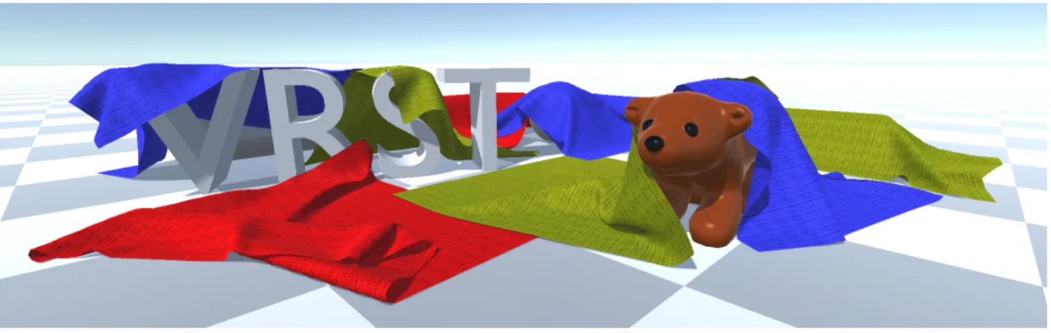
Figure 1: Eight sheets (each composed of ∼4k vertices) fall on static objects (including non-convex objects). Collision takes an average of 5.3 milliseconds per time-step in this scene.
Abstract
We propose a method to perform collision detection with cloths with ray-tracing at an interactive frame-rate. Our method is able to perform collision detection between cloths and volumetric objects (rigid or deformable) as well as collision detection between cloths (including auto-collision). Our method casts rays between objects to perform collision detection, and an inversion-handling algorithm is introduced to correct errors introduced by discrete simulations. GPU computing is used to improve the performances by parallelis-ing the ray-tracparallelis-ing. Our implementation handles scenes containparallelis-ing deformable objects at an interactive frame-rate, with collision de-tection lasting a few milliseconds.
CR Categories: Computer Graphics [I.3.5]: Computational Geometry and Object Modeling—Physically based modeling Computer Graphics [I.3.7]: Three-Dimensional Graphics and Realism—Raytracing
Keywords: collision detection, narrow-phase, ray-tracing
1
Introduction
Collision detection (CD) is an essential task for physics simulation; it is responsible for detecting colliding objects and producing con-tact points needed to compute an accurate physics response.
Col-∗francois.lehericey@irisa.fr †valerie.gouranton@irisa.fr ‡bruno.arnaldi@irisa.fr
lision detection is a bottleneck in virtual reality (VR) applications due to the complexity of the environments that we try to simulate. We want to simulate large environments with complex objects, such as non-convex shapes, and deformable objects (e.g. cloths). Col-lision detection must be done at a high frame-rate to satisfy the real-time constraint required by VR.
Nowadays, collision detection is decomposed in two phases: broad-phase and narrow-broad-phase. The broad-broad-phase takes as input the whole set of objects present in the simulation, and output a list of pairs of objects that might be in collision with simple tests (with bounding volumes). The narrow-phase takes these pairs and performs more accurate tests to detect collision and output contact points for the physics response. Our method belongs to the narrow-phase cate-gory and, thus, performs collision detection on pairs of objects. Recent methods use GPGPU (general-purpose computing on graph-ics processing units) to improve the performances by taking advan-tage of GPU computational power. For the broad-phase, [Liu et al. 2010] proposed a parallel implementation of the sweep-and-prune algorithm that improves the performances by orders of magnitude. [Pabst et al. 2010] showed that the complete collision detection pipeline (broad-phase and narrow-phase) can be implemented on GPU for scenes containing both rigid and deformable objects. Main contributions: we propose a narrow-phase collision detec-tion algorithm for cloths that use ray-tracing to detect collisions between two objects. Our method is able to perform discrete colli-sion detection between a piece of cloth and a volumetric object (in-cluding non-convex objects) as well as collision detection between cloths (including auto-collision). This algorithm is paired with a method to correct collision artefacts between cloths caused by dis-crete simulations. With disdis-crete simulations, artefacts can happen when objects have movement with higher amplitude than their sizes in a single time-step. This problem is critical with cloths because of their small thickness. Our solution detects these inversions and corrects them.
2
Related Work
In this section we review related work that is the most relevant to our contributions. For an exhaustive review on collision detection we refer the reader to [Teschner et al. 2005] and [Kockara et al. 2007].
2.1 Image-Based Collision Detection
Among all the narrow-phase methods, image-based methods use rendering techniques to detect collisions. Most of these methods do not need pre-processing as they use the objects in the form they used in rendering. This makes image-based methods highly suit-able for deformsuit-able objects. These methods are often adapted for GPU implementations as GPUs are designed to execute rendering algorithms. Image-based methods can be decomposed in two cate-gories: rasterisation and ray-tracing.
Rasterisation techniques render the scene in a layered depth image (LDI) that is post-processed to detect collision [Allard et al. 2010]. The CInDeR algorithm [Knott 2003] uses rasterisation to implicitly cast rays to detect collisions. The main drawback of rasterisation methods is the approximations that are introduced by the discreti-sation of space when rendering the layered depth image.
Ray-tracing methods can overcome these approximations. [Wang et al. 2012] use ray-tracing to compute an LDI with a higher den-sity around small features with a non-uniform ray sampling. [Her-mann et al. 2008] detect collision by casting rays from the vertices of the objects. Rays are cast in the inward direction and the ones that hit the interior of another object detect collisions (e.g. Figure 2). [Lehericey et al. 2013b] cast secondary rays in the outward di-rection to detect prediction (possible future collisions), which can be used to improve the detection and the physics response.
Figure 2: Hermann et al. algorithm in 2D. The plain arrow detects collisions (they hit the interior of the other object), whereas the dotted arrow does not detect a collision (it hits the other object from outside).
2.2 Collision Detection for Cloth Simulation
Collision detection for cloth simulation is a complex challenge and has been extensively studied. All pairs of features (vertex, trian-gle, ...) between objects have to be tested for collision; therefore, a query for a single pair has a complexity of O(n × m), with n and m being the number of features to test on each object. This high complexity is exacerbated by the constant deformations to which an object can be subject, which makes the design of accelerative methods complex. Nevertheless, numerous accelerative methods have been proposed to improve the performances by culling unnec-essary tests. [Teschner et al. 2003] use spatial hashing to improve the performances. [Tang et al. 2009] perform continuous collision detection with hierarchical culling and take into account triangle
connectivity.[Zheng and James 2012] perform self-collision culling by computing the amount of energy required by a deforming object in order to enter into self-collision.
[Brochu et al. 2012] address the problem of numerical inaccuracies, which can cause false-positive detections in continuous collision detection.
Some methods consider the space between the objects. [M¨uller et al. 2015] tessellate the air between the objects before the simula-tion. Inversions are handled by forcing the volume of tessellated el-ements to be positive. If large relative displacel-ements are present in the simulation, the tessellation needs to be optimised. Treating in-verted elements is linked to finite element simulation of deformable objects [Stomakhin et al. 2012; Irving et al. 2004].
[M¨uller and Chentanez 2010] proposed simulating cloth at two lev-els: coarse level and wrinkle level. At coarse level, simulation is performed with a simple mesh; the goal is to simulate the global be-haviour of the cloth. Then a wrinkle mesh is attached to the coarse mesh and simulated with constraint that prevents the wrinkle mesh from deviating above a given range. The goal of the wrinkle level is to simulate the local behaviour of the cloth that is responsible for wrinkle formations. To allow the formation of wrinkles, compres-sion of edges is allowed in the coarse simulation.
In some simulations, cloths can be put in an entangled state (because of a character animation, for example). [Baraff et al. 2003] introduce a cloth-untangling method that untangles cloth over time and converges to a non-interpenetrating state. [Volino and Magnenat-Thalmann 2006] propose a method that minimizes the length of the intersection contour.
3
Method Overview
With volumetric objects (rigid or deformable), collision detection can be performed by casting rays from the vertices inside the ob-ject, as outlined in [Hermann et al. 2008], and predictive rays out-side the object, as outlined in [Lehericey et al. 2013b]. In these methods, volumetric objects are represented by their surface (gen-erally a triangle mesh).
We propose to extend this narrow-phase method of collision detec-tion to handle cloths. While testing a pair of objects, our method can handle collision detection between a volumetric/cloth pair and a cloth/cloth pair (including self-collision detection).
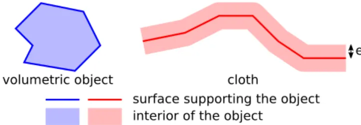
In our method, cloths are represented as a surface, but instead of representing the limits of the object, the surface represents the cen-tre layer of the object. Cloth interior expands towards both sides of the supporting surface up to a distance e (e = half cloth thickness), with e small regarding the dimensions of the cloth. Figure 3 shows our cloth representation compared to volumetric objects.
e surface supporting the object interior of the object
volumetric object cloth
Figure 3: Difference between volumetric objects and cloth repre-sentation.
To perform collision detection on a pair of objects, our method casts rays from each vertex of each object. Each pair (A; B) is
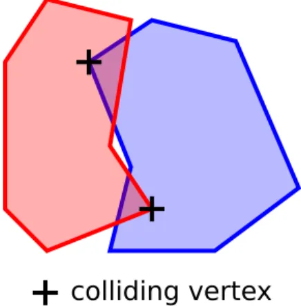
decom-posed in two tests: (A → B) and (B → A), where rays are cast respectively from A to B and B to A. Each test (A → B) performs a collision query of each vertex of A against B. The combination of the two tests enables us to test all of the vertices from both objects. Performing only one of the two tests could lead to false-negative detection. Figure 4 gives an example of where both tests need to be performed in order to detect all collisions.
colliding vertex
Figure 4: Two objects in collision. If we only test the vertices of one object, only one of the two colliding vertices would be discovered. To detect all collisions, vertices from each object need to be tested. We decompose the collision query of a pair (A; B) in two separate tests to take into account each object’s specificity. A and B can have different properties; each of these objects can be a volumet-ric object or a cloth. Given the differences in the representation of objects, all of the cases need to be specialised, namely: volumet-ric → volumetvolumet-ric, volumetvolumet-ric → cloth, cloth → volumetvolumet-ric, and cloth → cloth. In this paper the case of volumetric → volumetric is not considered here as is it part of the literature. Furthermore, de-pending on the nature of the target of the ray (rigid or deformable), different ray-tracing algorithms can be employed to improve the performances. Rigid objects can have complex accelerative struc-tures built to improve the performance of ray-tracing, whereas de-formable objects will use simpler accelerative structures that can be updated at a lighter cost.
Auto-collision detection for cloths is handled in the same way as collision between two different cloths. To handle auto-collision de-tection we simply add for each cloth C a test (C → C).
Our method outputs contact points that will be used by the physics response. Contact points give a pair of features – one from each ob-ject that is in an interpenetration state. In our method these features are a vertex (from which a ray was cast) and a triangle (which was hit by the ray). Each feature is coupled with a normal; this normal gives the optimal direction to push the objects to separate them. Our method works in three steps:
• We cast rays from the vertices of the objects. These rays are responsible for the detection of colliding features and the de-tection of possible future colliding features (predictions) (see Section 4.1).
• For the cloth vs. cloth test we apply an inversion detection al-gorithm. This test detects collision artefacts between cloths introduced when movements are too important in a single time-step (see Section 4.2).
• We generate contact points for the physics response. Contact points are generated from the result of the ray-tracing (and potentially corrected by the inversion detection algorithm).
Some post-processing is applied to ensure a correct physics response (see Section 4.3).
4
Ray-Traced Collision Detection for Cloths
This section will present the details of our ray-traced collision de-tection method for cloth.
4.1 Ray-Traced Detection
The first step in performing collision detection on a pair of objects is to cast rays from each vertex of each object of the pair. Two rays are cast from each vertex; one in the direction of the normal and one in the opposite direction of the normal.
One problem to address is to avoid detecting conflicting contact points. Contact points must be inside the colliding objects and the contact normal should give the direction to the shortest path to sep-arate the objects. Conflicting contact points are unreliable contact points detected either outside the objects or with a normal which does not give a correct path to separate the objects. These con-flicting contact points will cause errors in the physics response by generating opposing forces that can lock objects together.
(1)
(2)
collision rejected
Figure 5: Illustration of Hermann et al. conditions. Crossed-out arrows are rejected rays that do not satisfy a condition. In (1) the ray hits the target after leaving the source object. In (2) the ray hits the exterior of the target (contrary to the plain arrow). If the crossed-out arrows are used as contact points, then opposing con-straints will lock the objects together in the physics response. To avoid these conflicting contact points, Hermann et al. proposed using two conditions when testing collisions between two volumet-ric objects: (1) the ray must hit the target object before leaving the source object, and (2) the ray must hit the inside of the target object. These two conditions ensure that there will be no conflicting contact point that would lock the objects together in the physics response. An example can be found in Figure 5, where the crossed-out arrows are eliminated because it does not satisfy condition (1) or (2). Our new contributions include three new elementary tests that al-low the introduction of cloths into our collision detection method: volumetric → cloth, cloth → volumetric, and cloth → cloth. volumetric → cloth
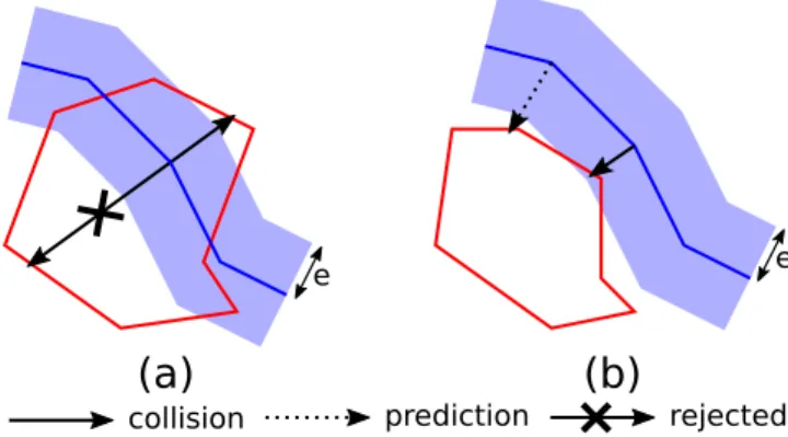
For a volumetric object the ray cast in the direction of the normal goes outside the object (called the outward ray) and the ray cast in the opposite direction of the normal goes inside the object (called the inward ray). Figure 6 gives an example of rays classified as collision, prediction or rejected by the inward ray or the outward ray.
The inward ray is only used to detect collisions. With cloths the second condition proposed by Hermann et al. is not feasible. Col-lision tests are processed on the supporting surface of the cloth (the
e e
(a)
(b)
collision prediction rejected Figure 6: Example of an accepted, predictive and rejected ray in a volumetric→ cloth test. In (a) a part of the cloth is completely inside the volumetric object, and collision is detected by inward rays if, and only if, the ray has a length inferior to half the exit dis-tance. In (b) the cloth touches the volumetric object, and collision is detected if the ray has a length inferior toe; otherwise the ray is classified as a prediction.
centre layer), which makes it impossible to know whether the ray hits inside or outside the object. Furthermore, requiring a vertex to be within the range of the thickness of the cloth would require high frame-rate tests in order to detect collisions on very thin cloth. To avoid detecting collisions on both sides of a volumetric object against a cloth (conflicting contact), we propose using a modified version of condition (1). Moreover, to avoid false-negative detec-tion against thin cloth we abandon condidetec-tion (2). The main idea is to select the shortest path to separate the objects, which is the most probable solution. With our method an inward ray is accepted if its length does not exceed half the exit distance (distance of the ray when it exits the source object). If the ray has a length higher than half the exit distance, then the cloth is closer to the other side of the object; collision will be detected on this other side. Figure 6.a gives an example. The plain arrow satisfies the condition, whereas the crossed-out arrow has a length superior to half the exit distance. In [Lehericey et al. 2013b] method, the outward ray is only used for collision predictions. With cloths we have to take into account the thickness of the cloth. Our solution is to classify cloth features detected by the outward ray as collision if the length of the ray is inferior to e; otherwise we classify it as a prediction. Figure 6.b gives an example. The plain arrow length is inferior to e, whereas the dotted arrow is classified as a prediction.
cloth → volumetric
With cloths, both rays are cast inside the object and exit it after traversing a distance e. Unlike volumetric objects, both rays cast from a cloth are treated in the same way. Figure 7 gives an example of collision detected from a cloth towards a volumetric object. When a ray cast by a cloth hits a volumetric object we have two cases: (a) the ray hits the inside of the volumetric object, or (b) the ray hits the outside of the volumetric object. In case (a), both rays cast from the same vertex will hit inside the other object (because the cloth vertex is inside the other object). We cannot use both rays to detect collision, as it would give an unreliable response (conflict-ing contact). In that case we classify the ray with the shortest length as a collision and we discard the other. Figure 7.a gives an example of such a case. The plain arrow is preferred over the crossed-out ar-row because of its shorter length. In case (b), we detect a collision if the ray has a length inferior to e (to take into account the cloth thickness); otherwise we classify it as a prediction. Figure 7.b gives
e
(a)
(b)
e
collision prediction rejected Figure 7: Example of an accepted, predictive and rejected ray in a cloth→ volumetric test. In (a) a part of the cloth is completely inside the volumetric object, with the shortest ray being selected as a collision. In (b) the cloth touches the volumetric object. Collision is detected if the ray has a length inferior toe; otherwise the ray is classified as a prediction.
an example of such a case. The plain arrow has a length inferior to e, whereas the dotted arrow is classified as a prediction.
cloth → cloth
Like the cloth → volumetric case, both rays are cast inside the ob-ject and exit it after traversing a distance e.
e' e
collision prediction Figure 8: Example of an accepted and predictive ray in a cloth → cloth test. The plain arrow has a length inferior toe + e0; therefore, it detects a collision, contrary to the dotted arrow that is classified as a prediction.
When detecting collision between two clothes, we have to take into account both cloth thicknesses (illustrated in Figure 8). When a ray cast by a cloth hits another cloth we detect a collision if the ray has a length inferior to e + e0(with e and e0the half thickness of each cloth); otherwise we classify it as a prediction.
4.2 Inversion Handling
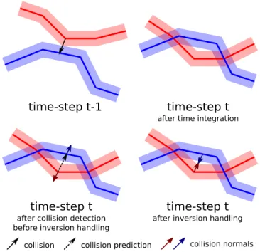
With discrete physics simulations, collision detection is executed after objects move with a delta-time. In this case, collision de-tection is performed when objects are in interpenetration and the correct response to apply has to be found. When small objects are present in a simulation, they can traverse each other during a single time-step. This problem is highly sensitive with cloths because of their small thickness and the relative independent movement of the vertices. Figure 9 gives an example of how an inversion between two vertices can happen.
When inversion happens between two cloths (or in self-collision), the two cloths behave like they are glued together. This is explained
time-step t-1
collision detection
and response
time integration
time-step t
Figure 9: Example of an inversion between two pieces of cloth. At time-stept − 1, no inversions are present. After applying the time integration an inversion is introduced in the simulation. If no inver-sion detection test is applied after colliinver-sion detection the physics response will maintain the inversion and act as a glue between the two objects.
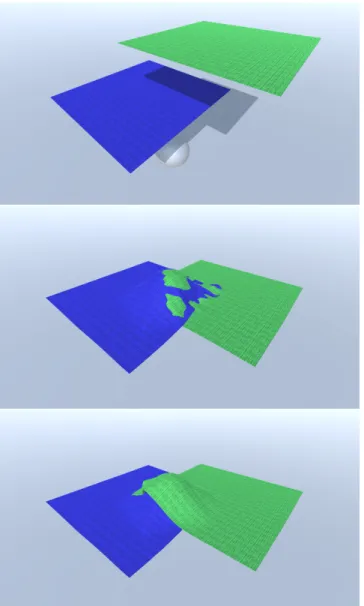
by the conflicting constraints between the cloths. The physics re-sponse tries to maintain each vertex on the side on which it was detected. Inversions also provoke visual artefacts. Inverted vertices are not rendered on the correct side of the other cloth and cause visual errors (e.g. Figure 11).
Our solution is to check the side of the colliding vertex regarding the colliding triangle and compare it with the side of the same vertex regarding the same triangle before time integration. If the vertex changes side regarding the triangle, we consider that we have an inversion; in such cases, we invert the direction of the normals of the contact points. The inversion of the direction of the normals will cause the physics response to push the vertex and the triangle in the opposing direction thus untangling the cloths.
When an inversion is detected, if the contact is classified as a pre-diction, then we need to reclassify it as a collision (e.g. Figure 10). This can happen when the vertex moves a distance higher than the thickness of the cloths in a single time-step. If the contact point is not reclassified, then it will be ignored by the physics response, which would leave the cloths in a tangled state. Should the same contact be detected in the next steps, the inversion detection algo-rithm would not be able to correct it as it only works on the last step result.
This method can be viewed as tetrahedra inversion detection, such as the one used in [M¨uller et al. 2015]. In Muller et al. method, air is tessellated with tetrahedra between the objects, with inversions being handled by constraining the air tetrahedra to have a positive volume. In our method, instead of relying on a complete tessellation of the air between the objects, we work on the pairs (vertex, trian-gle) detected by our collision detection method. We then prevent these pairs from inverting in a single time-step, which is equiva-lent to constraining the volume of the tetrahedron composed of the vertex and triangle to become negative. Contrary to Muller et al. methods our solution does not need to apply mesh optimisation to update the air tessellation when large rotation occur in the simula-tion, but our method is restricted to handle inversions that occur in a single time-step.
4.3 Contact Points Generation
After collision is detected and inversions are corrected we need to generate contact points for the physics response. To improve the reliability we use ray re-projection [Lehericey et al. 2013b] to comply with the MTD. The MTD (minimum translational distance [Cameron and Culley 1986]) is the shortest relative translation that
time-step t-1
time-step t
after collision detection before inversion handling
time-step t
after inversion handling
time-step t
after time integration
collision normals collision collision prediction
Figure 10: Example of a collision prediction that needs to be re-classified. At time-stept − 1, two pieces of cloth are in contact; after time integration they enter a colliding state. After collision detection some vertices are not detected as colliding but rather in near collision, because they are at a distance higher thane + e0. In-version detection is able to correct the normals of the contact point, and the contact point is reclassified as a collision to not be ignored by the physics response.
puts the two objects in contact (and not in interpenetration). Ray re-projection guarantees that the contact point gives the shortest trans-lation to separate the object relatively to the detected triangle by projecting the ray on the normal of the detected triangle.
The projection of the ray modifies the length of the ray and makes it shorter. With detection depending on the length of the ray, ray re-projection needs to be applied before performing the classifica-tion of contact points to avoid misclassifying an actual collision as a prediction. Figure 12 gives an example of where re-projection changes the result of the collision detection; if ray re-projection is not applied, then the ray would be wrongfully classified as a predic-tion. These errors, when present in a simulation, cause instabilities. Contact points are not detected at the distance that the physics re-sponse puts them, resulting in an alternation between a detected and undetected state.
Contact points are detected on the surface supporting the object. For cloths this surface does not represent an external surface of the cloth. To put the contact point of a cloth on the exterior surface of the object, the contact point should be translated in the opposite direction of the contact normal by a distance e as shown in Figure 13.
5
Results
We tested our ray-traced collision detection algorithm with a position-based physics response [Bender et al. 2013]. The simu-lation is implemented for GPU with OpenCL and is executed on an AMD FirePro W9100 at 60 frame per second.
Figure 11: Two pieces of cloth fall on a ball (top image). Without inversion detection, both cloths become entangled together (mid-dle image). With inversion detection a correct collision detection prevents the cloths from becoming entangled (bottom image).
5.1 Ray-Tracing Algorithms
Our method can use any existing ray-tracing algorithm to perform collision detection; in our tests we used three ray-tracing algo-rithms.
For rays cast on rigid objects we use a stack-less BVH traversal. This algorithm uses a bounding volume hierarchy (BVH) as an ac-celerative structure [Wald et al. 2007], with a stack-less ray traversal designed to maximise performance on GPU. The BVH is computed before the simulation and does not need to be updated because rigid objects does not undergo any deformations.
For rays cast on deformable objects we use a basic ray-tracing al-gorithm. This algorithm does not use any accelerative structure that would need to be updated. For improved performances, this algo-rithm is parallelised on GPU.
For rays cast on both rigid and deformable objects, we use an itera-tive ray-tracing algorithm in addition [Lehericey et al. 2013a]. This
e e
before re-projection
ray length > e
after re-projection
ray length < e
Figure 12: Effect of ray re-projection on the length of the rays. In this example the length of the ray is higher thane before re-projection – the ray is classified as a prediction. After applying re-projection the length of the ray becomes smaller thane – the ray is classified as a collision.
before repositioning
after repositioning
cloth cloth volumetric cloth cloth cloth volumetric cloth contact points collision normals
Figure 13: Examples of contact repositioning on a cloth/volumetric and a cloth/cloth collision. The contact points are moved along the contact normals to match the external surface.
algorithm can only be used when small displacements are present in the simulation over time. This algorithm can be used on both rigid and deformable objects, as the accelerative structure does not need to be updated when deformation occurs. The core idea of this method is to update the previous time-step when small displace-ments occur between objects; otherwise standard ray-tracing algo-rithms are used. When used, this algorithm takes as input the result of the collision detection of the previous time-step (including colli-sion predictions), and updates it while considering the new position of objects.
5.2 Performances
In the scene shown in Figure 1, eight sheets (each composed of 4200 vertices) are dropped on a static scene (composed of 9000 vertices). Collision detection takes an average of 5.3 milliseconds per time-step. This timing includes collision between the sheets and self-collisions.
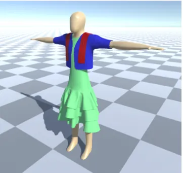
In the scene shown in Figure 14, a static mannequin (composed of 9800 vertices) wears a dress (11,000 vertices), a jacket (2700 ver-tices) and a scarf (3800 verver-tices). In this scene, collision detection
Figure 14: A three-layered dress (∼11k vertices) a jacket (∼3k vertices) and a scarf (∼4k vertices) on a mannequin. Collision detection takes an average of 4.3 milliseconds per time-step.
takes an average of 4.3 milliseconds per time-step. In this scene our method is able to handle a complex scenario where three layers of clothes are stacked. Up to 16,000 contact points are detected in every step between clothes and with the mannequin. The scarf lies on the jacket and touches the dress, the jacket lies on both the dress and mannequin, and no interpenetrations are present in the simu-lation. Auto-collisions are accurately detected on the three-layered dress, resulting in a visible volume and wrinkles.
Figure 15 shows a stress test for self-collision detection. A square piece of cloth is dropped on its side on an irregular ground. Our method is able to detect auto-collision occurring while hit-ting the ground resulhit-ting in the formation or wrinkle without self-interpenetration. Up to 3800 contact points are detected per time-step, including collisions between the cloth and the ground and auto-collisions on the cloth.
Figure 15: Stress test, in which a sheet falls on its side on an irreg-ular ground. In this scenario, complex self-collisions are present and our method is able to handle it efficiently.
Figure 16 shows user interaction with the cloth simulation.
Colli-Figure 16: Real-time interaction with cloth simulation. Our method runs in real-time, allowing users to interact with the cloth simulation. In this scenario, interaction is carried out with a Razer Hydra.
sion detection (and the physics response) runs in real-time, enabling users to interact with the virtual scenes. In our setup, bi-manual in-teraction is achieved with a Razer Hydra, allowing movements in three dimensions.
6
Conclusion and Future Work
We presented a method to perform collision detection for cloths us-ing ray-tracus-ing. Our method is able to perform collision detection between volumetric objects (rigid or deformable) and cloths as well as collision detection between cloths (including auto-collision). Our inversion-handling method is able to rectify errors introduced by discrete simulation.
Our implementation showed that out method can be used in real-time simulations of deformable objects and is able to take advantage of GPU computational power. In our use cases, users are able to interact with cloth simulation.
As in any discrete simulations, the velocities of the objects need to be limited depending on the frame-rate of the simulation. If objects move of a distance higher than their sizes in a single time-step, they can pass through another object without any collision being detected. Adjusting the direction of each ray toward the velocity vector of each vertex relatively to the movement of the target would give an approximation to continuous collision detection.
In future work we want to integrate untangling algorithms that work in the long term (several time-steps) to have more robust simulations. In addition, we want to investigate temporal consis-tency between cloths to improve performances. Estimation of the distance to collision (which is possible with collision predictions) paired with a measurement of displacement could be used to per-form culling on vertices until a collision is possible.
Varying thickness can also be studied. In our implementation each cloth has a constant thickness; however, it would be possible to handle cloth with varying thicknesses. In the two level simulation of [M¨uller and Chentanez 2010], the authors propose to limit the movement of the wrinkle vertices to half the cloth thickness to avoid self-collisions. Our method could be used for the coarse mesh sim-ulation. Varying thicknesses could be used to simulate the increased thickness of the coarse mesh when edges are compressed, which is explained by the formation of wrinkles on the wrinkle mesh. This would allow a greater field of freedom for the wrinkle vertices and allows them to produce wrinkles with higher amplitude.
References
ALLARD, J., FAURE, F., COURTECUISSE, H., FALIPOU, F., DURIEZ, C.,ANDKRY, P. 2010. Volume contact constraints at arbitrary resolution. ACM Transactions on Graphics (TOG) 29, 4, 82.
BARAFF, D., WITKIN, A., ANDKASS, M. 2003. Untangling cloth. In ACM Transactions on Graphics (TOG), vol. 22, ACM, 862–870.
BENDER, J., M ¨ULLER, M., OTADUY, M. A., ANDTESCHNER, M. 2013. Position-based methods for the simulation of solid objects in computer graphics. EUROGRAPHICS 2013 star. BROCHU, T., EDWARDS, E.,ANDBRIDSON, R. 2012. Efficient
geometrically exact continuous collision detection. ACM Trans-actions on Graphics (TOG) 31, 4, 96.
CAMERON, S.,ANDCULLEY, R. 1986. Determining the mini-mum translational distance between two convex polyhedra. In Robotics and Automation. Proceedings. 1986 IEEE Interna-tional Conference on, vol. 3, IEEE, 591–596.
HERMANN, E., FAURE, F., ANDRAFFIN, B. 2008. Ray-traced collision detection for deformable bodies. In GRAPP 2008, IN-STICC, 293–299.
IRVING, G., TERAN, J.,ANDFEDKIW, R. 2004. Invertible finite elements for robust simulation of large deformation. In Proceed-ings of the 2004 ACM SIGGRAPH/Eurographics symposium on Computer animation, Eurographics Association, 131–140. KNOTT, D. 2003. Cinder: Collision and interference detection in
real–time using graphics hardware.
KOCKARA, S., HALIC, T., IQBAL, K., BAYRAK, C.,ANDROWE, R. 2007. Collision detection: A survey. In Systems, Man and Cy-bernetics, 2007. ISIC. IEEE International Conference on, IEEE. LEHERICEY, F., GOURANTON, V.,ANDARNALDI, B. 2013. New iterative ray-traced collision detection algorithm for gpu archi-tectures. In Proceedings of the 19th ACM VRST, 215–218. LEHERICEY, F., GOURANTON, V., ARNALDI, B.,ET AL. 2013.
Ray-traced collision detection: Interpenetration control and multi-gpu performance. JVRC, 1–8.
LIU, F., HARADA, T., LEE, Y.,ANDKIM, Y. J. 2010. Real-time collision culling of a million bodies on graphics processing units. In ACM Transactions on Graphics (TOG), vol. 29, ACM, 154. M ¨ULLER, M.,ANDCHENTANEZ, N. 2010. Wrinkle meshes. In
Proceedings of the 2010 ACM SIGGRAPH/Eurographics sympo-sium on computer animation, Eurographics Association, 85–92. M ¨ULLER, M., CHENTANEZ, N., KIM, T.-Y.,ANDMACKLIN, M. 2015. Air meshes for robust collision handling. ACM Trans. Graph. 34, 4 (July), 133:1–133:9.
PABST, S., KOCH, A.,ANDSTRASSER, W. 2010. Fast and scal-able cpu/gpu collision detection for rigid and deformscal-able sur-faces. In Computer Graphics Forum, vol. 29, Wiley Online Li-brary, 1605–1612.
STOMAKHIN, A., HOWES, R., SCHROEDER, C., AND TERAN, J. M. 2012. Energetically consistent invertible elasticity. In Proceedings of the ACM SIGGRAPH/Eurographics Symposium on Computer Animation, Eurographics Association, 25–32. TANG, M., CURTIS, S., YOON, S.-E.,ANDMANOCHA, D. 2009.
Iccd: Interactive continuous collision detection between
de-formable models using connectivity-based culling. IEEE Trans-actions on Visualization and Computer Graphics 15, 544–557. TESCHNER, M., HEIDELBERGER, B., M ¨ULLER, M., POMER
-ANTES, D.,ANDGROSS, M. H. 2003. Optimized spatial hash-ing for collision detection of deformable objects. In VMV, vol. 3. TESCHNER, M., KIMMERLE, S., HEIDELBERGER, B., ZACH
-MANN, G., RAGHUPATHI, L., FUHRMANN, A., CANI, M.-P., FAURE, F., MAGNENAT-THALMANN, N., STRASSER, W.,
ET AL. 2005. Collision detection for deformable objects. In Computer graphics forum, vol. 24, Wiley Online Library. VOLINO, P., AND MAGNENAT-THALMANN, N. 2006.
Resolv-ing surface collisions through intersection contour minimization, vol. 25. ACM.
WALD, I., BOULOS, S., ANDSHIRLEY, P. 2007. Ray tracing deformable scenes using dynamic bounding volume hierarchies. ACM Transactions on Graphics (TOG) 26, 1, 6.
WANG, B., FAURE, F.,ANDPAI, D. K. 2012. Adaptive image-based intersection volume. ACM Trans. Graph. (Proc. SIG-GRAPH) 31, 4.
ZHENG, C.,ANDJAMES, D. L. 2012. Energy-based self-collision culling for arbitrary mesh deformations. ACM TOG 31, 4, 98.