HAL Id: hal-01644902
https://hal.archives-ouvertes.fr/hal-01644902
Submitted on 21 Feb 2018
HAL is a multi-disciplinary open access
archive for the deposit and dissemination of
sci-entific research documents, whether they are
pub-lished or not. The documents may come from
teaching and research institutions in France or
abroad, or from public or private research centers.
L’archive ouverte pluridisciplinaire HAL, est
destinée au dépôt et à la diffusion de documents
scientifiques de niveau recherche, publiés ou non,
émanant des établissements d’enseignement et de
recherche français ou étrangers, des laboratoires
publics ou privés.
A combined temporal tracking and stereo-correlation
technique for accurate measurement of 3D
displacements: application to sheet metal forming
D Garcia, Jean-José Orteu, Luc Penazzi
To cite this version:
D Garcia, Jean-José Orteu, Luc Penazzi. A combined temporal tracking and stereo-correlation
tech-nique for accurate measurement of 3D displacements: application to sheet metal forming. Journal of
Materials Processing Technology, Elsevier, 2002, 125-126, pp.736-742.
�10.1016/S0924-0136(02)00380-1�. �hal-01644902�
A combined temporal tracking and stereo-correlation technique
for accurate measurement of 3D displacements:
application to sheet metal forming
D. Garcia, J.J. Orteu
*, L. Penazzi
E´cole des Mines d’Albi-Carmaux, Campus Jarlard, 81013 Albi, France
Abstract
Optical methods that give displacement or strain fields are now emerging significantly in the mechanical sciences. Much work has been done on two dimensional (2D) displacement/strain measurement from a single camera but the proposed methods give only in plane strains. A binocular correlation based stereovision technique has been developed:
(a) to measure the three dimensional (3D) shape of a static object or
(b) to measure the strains of an object undergoing some 3D mechanical or thermal stress.
In this paper, the application of the stereo correlation technique to measure accurately the 3D shape of a stamped sheet metal part or the surface strain field undergone by the part during the stamping process is presented.
Keywords:Stereovision; Digital image correlation; 3D metrology; Experimental mechanics
1. Introduction
Optical methods that give displacement or strain fields are now emerging significantly in the mechanical sciences. Much work has been done on two dimensional (2D) dis placement/strain measurement from a single camera (see
[17,18] for a recent review). The proposed methods give
only in plane strains and raise some experimental difficul ties to guarantee the relative positions of the camera and the sample planes. To bypass these drawbacks, some work has been done on three dimensional (3D) displacement/strain measurement using two cameras or a single moving camera
[4,11,12,14,15,19,20].
Within the Material Research Center at E´cole des Mines d’Albi, the Artificial Vision and Thermography laboratory develops non contact methods for mechanical and thermal measurements in the field of material processing and shap ing technologies. In particular, we have developed a bino cular correlation based stereovision technique that can be used:
(a) to measure the 3D shape of a static object or
(b) to measure the strains of an object undergoing some 3D mechanical or thermal stress.
The points worked on are: strong and accurate calibration of a camera or a binocular stereovision sensor[6,9], 3D shape measurement by stereovision (and in particular by stereo correlation), 3D displacement/strain field measurement using in conjunction stereo correlation and pixel tracking in a sequence of stereo images. Due to the metrology aspect of the work, particular concern has been given to the accuracy of the proposed methods (accuracy of the camera calibration, accuracy of the image matching, subpixel cor relation, etc.).
The stereovision technique has been used to measure 3D strains on formed sheet metal parts, on inflated elastomer membranes or on refractory ceramics reinforced with metallic fibers[5,7,8,10,15].
The paper is organised as follows. In Section 2, the improved stereovision technique for 3D shape and 3D displacement/strain accurate measurement is presented. In
Section 3, an application of this method for the accurate
measurement of the 3D shape of a formed sheet metal part and the surface strain field undergone by the part during the stamping process is given.
2. Stereovision for 3D shape and 3D displacement/ strain measurement
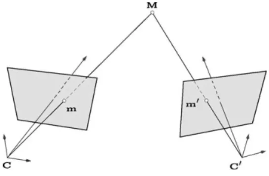
Binocular stereovision is a technique for building a 3D description of a scene observed from two slightly different viewpoints (seeFig. 1where M¼ ðxyzÞTis the 3D point to be measured, m¼ ðuvÞT and m0¼ ðu0v0ÞT
are its stereo projections in the images, C and C0are the optical centres
of the two cameras). From a pair of images, it is possible to compute the 3D co ordinates of a physical 3D point by triangulation assuming that:
1. The geometry of the stereo rig (i.e. the relative position and orientation of the two cameras) is known. This problem is solved by an off line camera calibration procedure.
2. The two image points m and m0 are matched, i.e. identified as corresponding to the same physical point M. This is called the stereo matching problem. The triangulation is a function of the disparity (difference of the two matched point co ordinates) and the calibration parameters.
2.1. Calibration of the stereovision sensor
Camera calibration is an important task in 3D computer vision, specially when metric data are required for applica tions involving accurate dimensional measurements. An original and flexible technique has been developed to easily calibrate a camera or a stereovision sensor. This technique leads to a highly accurate calibration[6,9].
The calibration parameters will be used throughout this paper at different stages: the correction of lens distortion, the rectification of the pairs of stereo images, and the calculation of the 3D position of a scene point from its stereo projections by triangulation.
2.2. Rectification of the stereo images
Given a point m in the left image I, if we look for its corresponding point m0 in the right image I0 (this is the stereo matching problem discussed in Section 2.3), it appears that m0belongs to a straight line of image I0, entirely
defined by the co ordinates of m, the relative position/ orientation of the two cameras and their intrinsic parameters: this is the so called epipolar line associated to m. This geometric constraint imposed by the imaging system, called epipolar constraint, is very important: thanks to it, during the stereo matching phase, a 2D search for correspondence can be transformed into a one dimensional one along the epipolar line.
When the cameras are perfectly aligned, the epipolar lines are horizontal and parallel: this greatly simplifies the search for correspondence since corresponding pixels are on the same row in both images. We call ‘‘disparity’’ the difference between the column number of the matched points. In practice, the mechanical alignment of the cameras is very difficult to obtain. Nevertheless, the problem can be solved at the processing level by applying a transformation (plane to plane homography) to each image of the initial stereo pair to obtain a new pair of stereo images corresponding to a virtual stereo rig with perfectly aligned cameras[2,13]. This rectification procedure uses the calibration parameters com puted in the off line camera calibration phase. Notice that during the rectification, the real distorted co ordinates (due to optical lens distortion) must be transformed into ideal distortion free ones.
It should be noted that, in practice, we never compute the rectified images, nor the undistorted images. In fact, we use the computed rectification homographies and the distortion parameters directly in the expression of the correlation function to work on the raw images. This new approach can achieve the highest matching accuracy by avoiding the pixel interpolations involved in the distortion correction and rectification of the images, as explained in the following sections.
2.3. Stereo matching
The main difficulty in stereovision is to establish corre spondences between pairs of images. Over the years, numer ous algorithms for image matching have been proposed. They can be classified in two categories:
1. Feature matching. The algorithms first extract salient primitives from the images, such as edge segments or contours, and match them in the views being considered. The methods are fast because only a small subset of the image pixels is used, but usually give few matches (sparse disparity maps).
2. Template matching. The algorithms attempt to correlate the grey levels of image patches in the views being considered, assuming that they present some similarity. The underlying assumption appears to be a valid one for relatively textured areas and for image pairs with small difference. These methods can give dense disparity maps.
In[15], a method based on stereovision for measuring strains in stamped 3D sheet metal parts was proposed. This method Fig. 1. Binocular stereovision.
falls into category 1 as it requires that a predefined pattern (a grid of squares) be applied to the sheet surface before stamping. Each image of the stereo pair is processed inde pendently in order to locate the grid intersections. The grid intersections are extracted in such a way as to allow an automatic matching between the two images provided that the operator matches manually a single pair of points.
We have also developed a stereo correlation technique that falls into category 2 and that is described in the present paper. With this technique, no regular grid needs to be applied to the part and the meshes used to compute the local strains are generated at the post processing level (we can generate meshes of any size, and in particular small ones to take into account large strain gradients).
Correlation scores are computed by measuring the simi larity of a fixed window in the left image to a shifting window in the right one (seeFig. 2). The second window is moved in the right image by integer increments along its corresponding epipolar line, searching for the increment (disparity) that leads to the best correlation value. Once this rough integer disparity is found, a refinement stage is operated on this match to estimate accurately the optimal shape of the correlation window in the right image and its subpixel disparity, according to the local orientation and curvature of the surface. This is achieved by using a modelzc
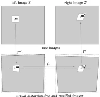
of the unknown disparity function (approximated by a Taylor expansion up to the second order, see Fig. 3) into the expression of the correlation function. This approach was first proposed by Devernay and Faugeras[3]for pre rectified images. In order to achieve a better accuracy (the distortion correction and rectification of images introduce a noise due to the underlying grey level interpolations), we proposed to improve their method by applying the correla tion function on the raw images. The lens distortion and rectification are taken into account in the correlation func tion, seeFig. 4. A point m in the raw left image is related to its corresponding distortion free and rectified point m by theG$1transformation. This point is matched in the right
rectified space to m by the zc transformation, then its
corresponding distorted and unrectified (raw) point into the right image is computed by the G0 transformation.
The grey level at this point is computed using a bi quintic spline interpolation (see[8]for more details).
It is well known that correlation based techniques are efficient on textured objects. If the objects are not textured enough, it only takes a few seconds to mark the object to be measured with a random pattern of spray paint[16]. 2.4. 3D reconstruction
Using the calibration parameters of each camera and the rectifying homographies, a classical triangulation method can be used to compute the 3D position of a scene point corresponding to a stereo pair of image points (seeFig. 1), assuming that their distortion has been corrected. Using the stereo correlation technique, all the points of the stereo images can be matched leading to a dense 3D reconstruction (seeFigs. 11 and 12) or we can try to match a small subset of Fig. 2. The principle of correlation-based stereo-matching on a
distortion-free and rectified pair of stereo images. [dmin, dmax] is the disparity range
used to restrict the search for correspondence.
Fig. 3. Pattern deformation for accurate correlation (shown in the distortion-free and rectified image space), d is the disparity.
Fig. 4. New correlation-based accurate stereo-matching on a raw pair of stereo images.
the image pixels (generally distributed over a virtual mesh) leading to a sparse 3D reconstruction (seeFigs. 13 and 14). 2.5. 3D displacement measurement
As already mentioned, much work has been done on 2D displacement/strain measurement, using a single camera, on gridded objects or using correlation based techniques. These methods can give only the in plane strains. The stereovision technique allows measurement of the 3D displacement field of an object undergoing some 3D deformation. It works as follows: using stereo correlation compute the 3D shape of the object at two different times t and tþ Dt, by matching the two images taken by the left camera (or the right one) at times t and tþ Dt (this is called temporal matching or tracking) compute the 3D displacement corresponding to each image point (seeFigs. 5 and 6).
The temporal matching problem is similar to the classical 2D displacement measurement problem. It is important to note that, in this case, we cannot use the epipolar constraint since we are dealing with two time varying images taken by a single camera.
In order to achieve a subpixel accuracy of the matched points, the local surface deformation is modelled by a Taylor expansion up to the second order, and used in the correlation function in a refinement stage of rough matches[8 16].
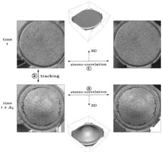
The process described inFig. 5corresponds to the ‘‘classi cal’’ method for computing 3D displacements from two pairs of stereo images. In order to achieve a better accuracy we have proposed an improved method (combined temporal tracking and stereo correlation) that operates simultaneously on the two pairs of stereo images. This new approach avoids the sucessive accumulation of the matching errors the match ing errors by maximising the correlation function over all the local transformation parameters (seeFigs. 4 and 7): stereo scopic transformation at time t and tþ Dt, and the temporal transformation1between time t and time tþ Dt.
When the object to be measured can be observed during its deformations (see [5] for an example), we can acquire a sequence of time varying pairs of stereo images with a sufficiently fast acquisition rate to guarantee a small defor mation between each image of the sequence. However, the case of sheet metal forming is critical: generally, we cannot observe the part during its deformation. Only a pair of images of the undeformed blank and a pair of images of the deformed part are available (seeSection 3). The technique has been applied successfully on deformed parts with up to 30% of strain between two successive pairs of stereo images. 2.6. 3D strain computation
In [15], the strain field was computed by analysing the initial and final configuration of an array of points marked on Fig. 5. Classical method for 3D displacement field computation.
Fig. 6. 3D displacement field computation.
Fig. 7. Our new improved method for 3D displacement field computation.
1Modelling the stereoscopic and the temporal transformations by a first
order Taylor expansion leads to 18 parameters with only 12 being independent, see[8]for a demonstration.
the surface. Each square element of the grid pattern was divided into triangular sub elements. The principal strains in each element was determined by comparing the undeformed and deformed triangles.
In the present work, no regular grid is marked on the surface of the part but we can compute the 3D mesh resulting from the 3D reconstruction of a Delaunay triangular mesh defined in an image (sparse reconstruction, seeFigs. 8 and 14). The strain field can be computed by using each 3D triangular element of the meshes before and after the deformation. The software AbaqusTMwas used for these computations.
2.7. Accuracy
The accuracy of 3D reconstruction depends on many factors:
& the quality of the cameras and their resolution,
& the configuration of the two cameras (angle between their optical axis) which governs the triangulation accuracy, & the accuracy of the stereovision sensor calibration, & the accuracy of the matched features in the images. The accuracy of the matched features depends on the type of extracted feature. In[15], gridded objects were used and the grid intersection extraction accuracy was 1/30 pixel. In[8], it was shown that the correlation technique leads to an accu racy better than 1/100 pixel.
Using high resolution digital cameras with 1024' 1024 pixels each, the 3D reconstruction relative accuracy in object space (the accuracy of co ordinate determination divided by the size of the object) achieved using stereo correlation is about 1/50000 (see[8,9]for a more detailed discussion on 3D reconstruction accuracy).
The strains are computed by numerical derivation from the displacements measured at several points distributed over a mesh. The strain at each point of the mesh is computed using neighbouring points (seeFig. 8). The accuracy of the strain computation depends on many elements: the discrete deriva tion scheme used (shape of the integration domain)[1], the accuracy of the displacement measurement, and the compu tation basis (mesh element spacing). The method proposed can reach an accuracy of 0.05% on the computed strains with triangular elements measuring 50 pixels.
3. Application to sheet metal forming
In this section, the application of the stereo correlation technique to measure accurately the 3D shape of a stamped sheet metal part or the surface strain field undergone by the part during the stamping process is presented.
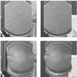
InFig. 9, the experimental setup (the stereo rig made up of two high resolution digital cameras) and an example of a stamped metal part are shown. It should be noted that the part shows some stamping defaults: this example was chosen as a test for determining the performance of our technique because the classical correlation techniques usually fail (due to the high apparent deformation of the surface texture in the stereo images). Fig. 10 shows the pairs of stereo images taken before and after forming.
Fig. 11shows the 3D shape of the undeformed aluminium
blank and of the formed part.Fig. 12shows another formed sheet metal part and a close view to get an idea of the Fig. 8. 3D deformation field computation.
Fig. 9. The formed sheet metal part and the experimental setup (courtesy of LMSo, INSA Lyon, France).
Fig. 10. Two pairs of stereo images taken respectively before (top) and after (bottom) the forming operation.
achieved accuracy. Two very interesting details can be observed.
The aluminium sheet was stamped over a steel sheet with a hole in its middle in order to concentrate the stress in the middle of the blank. The figure clearly shows the mark of the circular edge of the hole through the other side of the part. This mark is barely visible to the naked eye. The striction of the front aluminium sheet can also be seen.
Fig. 14shows the result of the computation of the max
imal strains: up to 25% located on the top surface of the aluminium sheet.
In classical grid methods, the grid (squares or circles) used for strains computation is fixed a priori before the forming operation. With the stereo correlation method, the mesh is defined after the forming operation, thus leading to a great flexibility: it is adaptable to strain gradients.
Fig. 11. 3D shape of the undeformed blank (left) and of the stamped part (right) computed respectively from the pairs of stereo images ofFig. 10. These are dense reconstructions made up of about one million 3D points.
Fig. 12. (a) 3D shape of another stamped sheet metal part; (b) close view to show the accuracy of the dense 3D reconstruction.
Fig. 13. Combined stereo-correlation and pixel tracking on a Delaunay triangular mesh. The mesh (3000 nodes, 6000 triangles with sides of about 10 pixels long) has been defined in the left image of the initial pair of stereo images (upper).
4. Conclusion
A new accurate stereovision technique for measuring the 3D shape of a static object or the 3D displacement field of a deformed object has been developed. Much attention has been paid to identifying the sources of errors that may be found in the previous approaches mentioned in the literature and we have proposed to bypass them: by developing an accurate calibration technique of the stereovision sensor
[6,9], by reducing the number of interpolation operations
to the minimum and by combining the stereo and tracking processes.
These improvements to the correlation based stereovision method have enabled a great step towards accurate 3D measurements in experimental mechanics.
References
[1] L. Allais, M. Bornert, T. Bretheau, D. Caldemaison, Experimental characterization of the local strain field in a heterogeneous elastoplastic material, Acta Metall. Mater. 42 (11) (1994) 3865 3880. [2] N. Ayache, C. Hansen, Rectification of images for binocular and trinocular stereovision, in: Proceedings of the Ninth IEEE Interna-tional Conference on Pattern Recognition, Roma, Italy, November 1988, pp. 11 16.
[3] F. Devernay, O. Faugeras, Computing Differential Properties of 3-D Shapes from Stereoscopic Images without 3-D Models, Research Report 2304, INRIA, July 1994.
[4] K. Galanulis, A. Hofmann, Determination of forming limit diagrams using an optical measurement system, in: Proceedings of the Seventh International Conference on Sheet Metal SheMet’99, Erlangen, Germany, September 27 28, 1999.
[5] D. Garcia, J.J. Orteu, 3D Deformation measurement using stereo-correlation applied to the forming of metal or elastomer sheets, in: Proceedings of the International Workshop on Video-controlled Materials Testing and In-situ Microstructural Characterization, Nancy, France, November 16 18, 1999.
[6] D. Garcia, J.J. Orteu, M. Devy, Accurate Calibration of a Stereovision Sensor: Comparison of Different Approaches, Vision, Modeling, and Visualization 2000, Saarbru¨cken, Germany, Novem-ber 22 24, 2000.
[7] D. Garcia, J.J. Orteu, 3D Deformation measurement using stereo-correlation applied to experimental mechanics, in: Proceedings of the
10th FIG International Symposium on Deformation Measurements, Orange, CA, March 19 22, 2001.
[8] D. Garcia, Mesure de formes et de champs de de´placements tridimensionnels par ste´re´o-corre´lation d’images, Ph.D. Thesis, Institut National Polytechnique de Toulouse, France, December 21, 2001. [9] D. Garcia, J.J. Orteu, M. Devy, Accurate Calibration of a
Stereovision Sensor for 3D Metrology Applications, Image and Vision Computing, Elsevier, Amsterdam, submitted for publication. [10] D. Garcia, J.J. Orteu, T. Cutard, E. Cailleux, Application of stereovision to the mechanical characterization of refractory ceramics reinforced with metallic fibers, in: Proceedings of SEM Conference on Experimental and Applied Mechanics, Milwaukee, WI, June 10 12, 2002.
[11] Z.L. Kahn-Jetter, T.C. Chu, Three-dimensional displacement mea-surements using digital image correlation and photogrammic analysis, Exp. Mech. 30 (1) (1990) 10 16.
[12] N. Langerak, E. Atzema, J. Essing, Strain measurements with the PHASTTM system, International Deep Drawing Research Group
(IDDRG’2000) Meeting of the Working Groups, Ann Arbor, MI, June 8 9, 2000.
[13] C. Loop, Z. Zhang, Computing Rectifying Homographies for Stereo Vision, Microsoft Research Technical Report MSR-TR-99-21, April 1999.
[14] P.F. Luo, Y.J. Chao, M.A. Sutton, W.H. Peters, Accurate measure-ment of three-dimensional deformable and rigid bodies using computer vision, Exp. Mech. 33 (2) (1993) 123 132.
[15] J.J. Orteu, V. Garric, M. Devy, Camera calibration for 3D reconstruction: application to the measure of 3D deformations on sheet ‘‘metal parts’’, in: Proceedings of European Symposium on Lasers, Optics and Vision in Manufacturing, Munich, Germany, June 16 20, 1997.
[16] M.A. Sutton, W.J. Wolters, W.H. Peters, W.F. Ranson, S.R. McNeill, Determination of displacements using an improved digital correlation method, Image Vision Comput. 1 (3) (1983) 133 139.
[17] M.A. Sutton, S.R. McNeill, J.D. Helm, H.W. Schreier, Computer vision applied to shape and deformation measurement, in: P.K. Rastogi, D. Inaudi (Eds.), Trends in Optical Nondestructive Testing and Inspection, Elsevier, Amsterdam, 2000.
[18] M.A. Sutton, S.R. McNeill, J.D. Helm, Y.J. Chao, Advances in two-dimensional and three-two-dimensional computer vision, in: P.K. Rastogi (Ed.), Photomechanics, Topics Applied Physics, Vol. 77, Springer, Berlin, 2000, pp. 323 372.
[19] P. Synnergren, M. Sjo¨dahl, A stereoscopic digital speckle photo-graphy system for 3-D displacement field measurements, Opt. Lasers Eng. 31 (1999) 425 443.
[20] J.H. Vogel. D. Lee, An automated two-view method for determining strain distributions on deformed surfaces, J. Mater. Shap. Technol. 6 (1989).