I
Université du Québec
Institut national de la recherche scientifique
Centre Énergie Matériaux Télécommunications
Antennes Reconfigurables en Diagramme de Rayonnement à base
de Surfaces Sélectives de Fréquence
(Reconfigurable Radiation Pattern Antennas Based on Frequency
Selective Surfaces)
Par
Suhair Mansoor Mahmood
Thèse présentée pour l'obtention du grade de Philosophiae Doctor (Ph.D.) en Télécommunications
Jury d’évaluation
Examinateur externe Dr. Chan-Wang Park
Université de Québec à Rimouski (UQAR) Examinateur externe Dr. Khelifa Hettak
Communication Research Center Canada (CRC) Président du jury Dr. Serioja Ovidiu Tatu
INRS-Énergie Matériaux Télécommunications Directeur de recherche Dr. Tayeb A. Denidni
INRS-Énergie Matériaux Télécommunications
II
A
BSTRACTReconfigurable antennas have recently formed a popular research topic. They are attracting the interest of many industry professionals. This is basically due to the growing demands for more functionality while occupying the same or even smaller physical volume. Using various antennas for wireless applications is no longer effective because having several antennas take too much space. Reconfigurable antennas are the best solution to provide a better performance in terms of flexibility, efficiency and combination of several electromagnetic spectrum applications. Frequency selective surfaces are exploited in many communication applications, especially in designing reconfigurable antennas due to their ability to control the electromagnetic field. A frequency selective surface is an important figure concept in reconfigurable antenna structures and has developed rapidly due to their unique properties in suppressing the surface wave propagation.
The main topic of this research is to design new reconfigurable radiation pattern antennas with enhanced performance by using switchable frequency selective surfaces. The antenna consists of a central radiating source surrounded by switchable frequency selective surface unit cells to give the antenna beam, shaping capability to scan 360 degree in the azimuth plane. Novel switchable frequency selective surface unit cells with various structures are designed and their characteristics are compared in both the reflective and transparent states. The reconfigurable response is the basic concept in the antenna design. This is achieved by adding PIN diodes to the lines that will connect or disconnect the unit cells and transform the frequency selective surface to be either a reflective or a transparent surface. As a consequence, switching the frequency selective surface PIN diodes leads to control the antenna beam direction.
In this thesis, two novel reconfigurable antennas with frequency selective surface unit cells are presented, each antenna works at a different frequency band. The switchable frequency selective surface utilized in the proposed antennas operates at different frequency bands. The research topic in this thesis includes investigations and techniques to increase the bandwidth and improve the radiation characteristics of the
III
reconfigurable antennas by using new switchable frequency selective surface unit cells. Experimental results show the preference of the proposed antennas over those presented in the literature. Thus, two new reconfigurable antennas are implemented and their enhanced performances in terms of bandwidth are proven.
V
T
ABLE OFC
ONTENTS Abstract ... II Table of Contents ... V List of Figures ... IX List of Tables ... XV1 Chapter One: Introduction ... 1
1.1 Motivations ... 1
1.2 Research problem and objectives ... 2
1.3 Thesis contribution ... 5
1.4 Literature review ... 6
1.5 Frequency selective surface applications ... 7
1.6 Frequency selective surface applications in antennas ... 11
1.7 Thesis organization ... 12
2 Chapter Two: General FSS Theory and Design ... 14
2.1 Introduction ... 14
2.2 Frequency selective surfaces ... 14
2.3 Frequency selective surface design ... 15
2.4 Switchable frequency selective surfaces ... 16
2.5 PIN diodes integration in FSS ... 18
2.5.1 Pin diode lumped elements influence on FSS performance ... 18
2.5.2 PIN diodes impact on FSS performance ... 21
2.6 Conclusion ... 24
VI
3.1 Introduction ... 26
3.2 Switchable frequency selective surface unit cell design ... 28
3.2.1 Planar strip switchable FSS unit-cell ... 29
3.2.2 Square switchable FSS unit-cell ... 32
3.2.3 Circular switchable FSS unit-cell ... 38
3.2.4 Triangle switchable FSS unit-cell ... 42
3.3 FSS structures comparison ... 47
3.4 Conclusion ... 50
4 Chapter Four: Reconfigurable Radiation Pattern Antenna (one) ... 52
4.1 Introduction ... 52
4.2 Reconfigurable radiation pattern antenna application ... 53
4.3 FSS unit-cell design at f2 ... 53
4.4 Nonagon reconfigurable pattern antenna design ... 58
4.5 Antenna measurements and results ... 60
4.6 Matching and realized gain bandwidth relation ... 62
4.7 Radiation pattern measurements ... 67
4.8 Reconfigurable antenna bandwidth ... 70
4.9 Conclusion ... 75
5 Chapter Five: Reconfigurable Radiation Pattern Antenna (two) ... 76
5.1 Introduction ... 76
5.2 FSS unit-cell design at f1 ... 76
5.3 Pattern reconfigurable antenna design and steering mechanism ... 82
VII
5.5 Conclusion ... 89
6 Chapter Six: Conclusions and future work ... 90
6.1 Introduction ... 90
6.2 Conclusions ... 90
6.3 Future work ... 92
7 CHAPITRE Seven: Résumé ... 94
7.1 Motivations ... 94
7.2 Problème et objectifs de recherche ... 95
7.3 Contributions de la thèse ... 97
7.4 Surfaces sélectives de fréquence ... 98
7.5 Antenne reconfigurable en diagramme de rayonnement ... 100
7.5.1 Introduction ... 100
7.5.2 Conception de la cellule unitaire FSS à la fréquence f2 ... 101
7.6 Antenne reconfigurable de forme ennéagone ... 103
7.6.1 Fabrication et résultats de mesure ... 105
7.6.2 Diagrammes de rayonnement mesurés ... 106
7.7 La deuxième antenne reconfigurable en diagramme de rayonnement .. 109
7.7.1 Introduction ... 109
7.7.2 La Cellule de FSS à la fréquence f1 ... 110
7.7.3 Configuration de l’antenne cylindrique reconfigurable ... 116
7.7.4 Résultats expérimentaux et discussions ... 121
7.8 Conclusions ... 124
IX
L
IST OFF
IGURESFigure 1-1 Communication links using steerable antennas [69]. ... 1
Figure 1-2 An F-117 Nighthawk stealth strike aircraft flying over Nevada in August 2002 [36]. ... 8
Figure 1-3 The French stealth frigate Surcouf (1997-present day) [37]. ... 8
Figure 1-4 Japan – Misawa Cryptology operation center [38]. ... 9
Figure 1-5 USA San Antonio with FSS installed to cover the antennas. ... 9
Figure 1-6 FSS glass windows for buildings [41]. ... 10
Figure 1-7 FSS applications in RCS control [43]. ... 11
Figure 2-1 FSS filter responses (a) Low-pass. (b) High-pass. (c) stop. (d) Band-pass. [50] ... 15
Figure 2-2 An arbitrary FSS unit cell with its transmission coefficient. Dimensions of the unit cell is about 16 mm. ... 16
Figure 2-3 Switchable frequency selective surface with PIN diodes integrated, unit cell dimensions = 14X18.7 mm ... 17
Figure 2-4 Proposed FSS structure. Dimensions (millimeters): W = 10, L = 10, Wd = 5.25, Wf = 1.5, Sb = 1.85, S = 0.5. (a) FSS with discontinuous lines in reflective state. (b) FSS with continuous lines in transparent state. (c) FSS with PIN diode. ... 19
Figure 2-5 Frequency response of the proposed switchable FSS ... 20
Figure 2-6 Ring FSS. (a) Proposed continuous FSS. (b) Proposed discontinuous FSS. (c) Conventional ring FSS. (d) Conventional ring FSS with four gaps. (e) Switchable conventional FSS. (f) Switchable proposed FSS. Dimensions (in millimetres) are M = 1.5, L = 10, K =0.5, P = 2.475, S = 0.5, R = 2.15 ... 22
Figure 2-7 Transmission coefficient of ring FSS with single PIN diode ... 23
X
Figure 3-1 Proposed FSS unit cell structure. ... 27
Figure 3-2 Reflective and transparent performance for f1 and f2. ... 28
Figure 3-3 Conventional strip line FSS unit cell-Dimensions (mm): M=1.5, L=10, Y=.5, K=0.5, Y=0.5. ... 29
Figure 3-4 Strip line FSS transmission coefficient for line width 1.5mm ... 30
Figure 3-5 Strip line FSS transmission coefficient for line width 0.5mm ... 30
Figure 3-6 Strip line FSS transmission coefficient in the reflective and transparent states. ... 31
Figure 3-7 Strip line FSS transmission coefficient in the reflective and transparent states at f1 ... 32
Figure 3-8 Square switchable FSS unit cells -Dimensions (mm): M=1.5, L=10, Y=0.5, K=0.5, P=2.375, S=0.5, A=5.25 ... 33
Figure 3-9 Square FSS transmission coefficient in the transparent and reflective state. ... 35
Figure 3-10 Square FSS transmission coefficient in the reflective state at f2. ... 36
Figure 3-11 Square FSS transmission coefficient in the transparent state at f2. ... 36
Figure 3-12 Square FSS transmission coefficient in the transparent state at f1. ... 37
Figure 3-13 Square FSS transmission coefficient in the reflective state at f1. ... 38
Figure 3-14 Ring FSS unit cells. Dimensions: M=1.5, L=10, Y=0.5, K=0.5, P=2.375, S=0.5, R=2.625. (mm) ... 39
Figure 3-15 Circular FSS transmission coefficient in the transparent and reflective state at f2. ... 40
Figure 3-16 Circular FSS transmission coefficient in the reflective state at f2. ... 40
Figure 3-17 Circular FSS transmission coefficient in the transparent state at f2. ... 41
XI
Figure 3-19 Circular FSS transmission coefficient in the reflective state at f1. ... 42
Figure 3-20 Triangle FSS unit cells. Dimensions : M = 1.5, L = 10, Y = 0.5, K = 0.5, P = 2.375, S = 0.5, H = 5.25 (mm). ... 43
Figure 3-21 Triangular FSS transmission coefficient in the transparent and reflective state at f2. ... 44
Figure 3-22 Triangle FSS transmission coefficient in the reflective state at f2. ... 44
Figure 3-23 Triangle FSS transmission coefficient in the transparent state at f2. ... 45
Figure 3-24 Triangle FSS transmission coefficient in the transparent state at f1. ... 46
Figure 3-25 Triangle FSS transmission coefficient in the reflective state at f1. ... 46
Figure 3-26 FSS structures transmission coefficient in the transparent state at f1. ... 47
Figure 3-27 FSS structures transmission coefficient in the reflective state at f1. ... 48
Figure 3-28 Proposed FSS unit cells ... 49
Figure 4-1 FSS unit cell. Dimensions in millimetres: W=18.7, L=14, Wd=8.9, K=3, Sc=1, Ld=8.9, Sb=0.8, S=0.5, Wf=3 ... 54
Figure 4-2 FSS transmission coefficient. Dimensions changed in (B): Wd=6, Ld=6 mm ... 55
Figure 4-3 FSS transmission coefficient. Dimensions changed in (C): Wd=11, Ld=11 mm ... 56
Figure 4-4 Simulated transmission coefficient of the proposed FSS unit cell. © 2016 IEEE ... 56
Figure 4-5 Y-Z plane, FSS electric field distribution in the reflective state. © 2016 IEEE ... 57
Figure 4-6 Y-Z plane, FSS electric field distribution in the transparent state. © 2016 IEEE ... 58 Figure 4-7 Proposed reconfigurable antenna, total length is 170mm and radius is
XII
R=30mm. (a) photo of the antenna. (b) The dipole feed inside the antenna. ... 59
Figure 4-8 Measured reflection coefficient of the antenna and dipole. © 2016 IEEE .... 61
Figure 4-9 Simulated and measured realized gain of the proposed antenna. © 2016 IEEE ... 61
Figure 4-10 Measured results for Antenna-I (a) Measured reflection coefficient [54]-page 2235. ... 63
Figure 4-11 Measured results for Antenna-II: (a) Measured reflection coefficient [54]-page 2235. ... 64
Figure 4-12 Measured gains for Antenna-I and II compared to the simulation. [54] -page 2236. ... 64
Figure 4-13 Measured reflection coefficients of the three fabricated antenna prototypes compared to the simulated one. [34]-page 672. © 2013 IEEE ... 65
Figure 4-14 Measured realized gains of the three fabricated antenna prototypes compared to the simulated one. [34]-page 672. © 2013 IEEE ... 65
Figure 4-15 Simulation and measurement results of S11 . [65] - page 171. © 2015 IEEE ... 66
Figure 4-16 Simulation and measurement results: realized gain in H-plane. [65] - page 172. © 2015 IEEE ... 66
Figure 4-17 Measured H-plane pattern, co-polar, through 300MHz. © 2016 IEEE ... 67
Figure 4-18 Measured H-plane pattern, cross-polar. © 2016 IEEE ... 68
Figure 4-19 Measured E-plane radiation pattern, through 300MHz. © 2016 IEEE ... 68
Figure 4-20 United States frequency spectrum. ... 70
Figure 4-21 Measured radiation pattern E-plane ... 71
Figure 4-22 Measured radiation pattern H-plane ... 71
XIII
Figure 4-24 Measured radiation pattern N=3 (a) H-Plane (b) E-plane [65]. © 2015 IEEE
... 73
Figure 4-25 Measured radiation pattern in N=7 (a) H-Plane (b) E-plane [65]. © 2015 IEEE ... 73
Figure 4-26 FSS unit cell Transmission coefficient [31]. © 2013 IEEE ... 74
Figure 4-27 Measured radiation pattern E-plane [31]. © 2013 IEEE ... 74
Figure 5-1 Proposed FSS unit cell structure. (a) Transparent state. (b) Reflective state. ... 77
Figure 5-2 FSS transmission coefficients for reflective and transparent states, with and without integrated PIN diodes. ... 78
Figure 5-3 Measured and simulated transmission coefficients for the transparent state. ... 79
Figure 5-4 FSS measured and simulated transmission coefficients in the reflective and transparent states with diodes. ... 80
Figure 5-5 (a) Electric field distribution for the transparent state in the Y-Z plane. (b) Electric field distribution for the reflective state in the Y-Z plane. ... 81
Figure 5-6 Top view of the realized cylindrical structure. dL is width of the FSS unit cell, =0.1976 rad =11.32°, t=24.969mm, r=25.4648mm, F=2.25GHz, k0=47.156 [1/M], Δϕ= k0 (r-t)= 0.0233 rad = 1.34º (phase shift between points A and B) ... 83
Figure 5-7 Proposed antenna (a) Photo of the fabricated antenna.(b) The FSS shield hole for the RF-cable entrance.(c) Top and side view antenna design... 84
Figure 5-8 H-plane radiation pattern for six angles ... 85
Figure 5-9 Antenna beam-steering mechanism ... 86
Figure 5-10 Measured reflection coefficient ... 87
XIV
Figure 5-12 Measured E-plane radiation pattern. ... 88 Figure 7-1 Liens de communication en utilisant des antennes reconfigurables [69]. .... 94 Figure 7-2 La structure de la cellule FSS proposée. ... 99 Figure 7-3 le coefficient de transmission simulé de la cellule FSS, pour f1et f2. ... 100 Figure 7-4 Structure de la cellule unitaire de FSS. Dimensions en millimètre: W=18.7, L=14, Wd=8.9, K=3, Sc=1, Ld=8.9, Sb=0.8, S=0.5, Wf=3. ... 101 Figure 7-5 le coefficient de transmission simulé de la cellule FSS ... 102 Figure 7-6 L’antenne reconfigurable proposée, la longueur totale est 170mm et un rayon R=30mm. (a) la photo de l’antenne. (b) le dipôle d’alimentation à l’intérieur de l’antenne. ... 104 Figure 7-7 Le coefficient de réflexion mesuré de l’antenne et du dipôle... 105 Figure 7-8 Le gain simulé et mesuré de l’antenne proposée ... 106 Figure 7-9 Diagramme de rayonnement co-pol mesuré dans le plan H à travers la bande 300MHz ... 107 Figure 7-10 Diagramme de rayonnement cross-pol mesuré dans le plan H à travers la bande 300MHz. ... 107 Figure 7-11 Diagrammes de rayonnement mesurés à travers la bande 300MHz ... 108 Figure 7-12 La structure de la cellule FSS proposée. (a) état transparent. (b) état réfléchissant. ... 110 Figure 7-13 les coefficients de transmission des FSS pour les états transparent et réfléchissant, avec et sans les diodes PIN intégrées. ... 112 Figure 7-14 Les coefficients de transmissions simulés et mesures pour l’état transparent ... 113 Figure 7-15 Les coefficients de transmission simulés et mesurés de la cellule FSS dans l’état réfléchissant et transparent. ... 114
XV
Figure 7-16 (a) La distribution du champ électrique à l'état transparent dans le plan Y-Z.
(b) La distribution du champ électrique à l'état réfléchissant dans le plan Y-Z. ... 115
Figure 7-17 Vue d'en haut de la structure cylindrique dL est la largeur de la cellule FSS, θ=0.1976 rad =11.32°, t=24.969mm, r=25.4648mm, F=2.25GHz, k0=47.156 m^-1, Δϕ= k0 (r-t)= 0.0233 rad = 1.34º (le déphasage entre le point A and B) ... 118
Figure 7-18 Antenne proposée (a) Photographie de l’antenne fabriquée, (b) Le trou du bouclier FSS pour le câble RF de l’entrée. ... 119
Figure 7-19 Diagramme de rayonnement pour six angle ... 120
Figure 7-20 Mécanisme de pilotage de faisceau de l’antenne ... 121
Figure 7-21 Coefficient de réflexion mesuré ... 122
Figure 7-22 Diagramme de rayonnement mesuré dans le plan H, à travers 300 MHz. ... 123
Figure 7-23 Diagramme de rayonnement mesuré dans le plan E, à travers 300 MHz 123
L
IST OFT
ABLES Table 2-1 Switchable FSS transmitted and reflected power percentages with PIN diodes integrated ... 21Table 2-2 Single pin diode unit cell ... 25
Table 2-3 Four pin diode unit cell ... 25
Table 3-1 Switchable FSS unit cells comparison ... 51
Table 4-1 Comparison of the antennas ... 69
Table 6-1 Comparison of the antennas ... 92
Tableau 7-1 Comparaison des antennes ... 109
1
1 C
HAPTERO
NE:
I
NTRODUCTION1.1 Motivations
Many military and civil applications for reconfigurable antennas can be seated in industry [1-3]. For example, communication between a satellite and a moving transportation object needs to have a steerable antenna to keep the connection stable [4]. Steerable antennas change its radiation direction according to the object position to stay on track. Reconfigurable antennas can allow the delivery of broadband internet access to passengers in many transmission categories as shown in the Fig. 1-1. Also, GPS connection and other types of important links of communications could be delivered [5].
In near future, the demand for broadband is insatiable not just for home and office users but also for mobile users, as Cisco Systems, San Jose, California, estimates that [6]: “About three quarters of the world’s mobile data traffic will become video by the year 2019, and the smart phone average will generate about 4.0GB of traffic per month by the year 2019".This highlights the need for wideband reconfigurable antennas to cover the expanded high data rate.
2
Steering the antenna could be done by either mechanical or electronic methods. Mechanical steering is achieved by repositioning and moving the antenna to reach the intended characteristics. However, the mechanical approach is criticized by its low speed and complex system installation.
Phased arrays have been used for many years as reconfigurable antennas; they can steer the antenna pattern in an electronic manner. The phase shifters steer the antenna beam when integrating active switching components such as PIN diodes, RF micro electro mechanical systems (RF MEMS) or any other switchable components. These switching components limit the speed and losses of the antenna due to their undesired parasitic elements. Both the mechanical and electronic methods result in extreme expensive and complex systems [7]. Therefore, intensive research has been made in many directions to find other alternatives and different approaches in this field. One of these alternatives is to use frequency selective surface (FSS) in reconfigurable antennas. This approach offers more functionality for an antenna, more versatility, robustness, less cost and a significant save in size and space [5, 8]. Thus, research in this field is very important and is one of the most popular fields nowadays. The thesis proposes reconfigurable antennas based on FSS with enhanced operating bandwidth.
1.2 Research problem and objectives
Reconfigurable antennas have been around since 1930 [9], they are becoming even more interesting for industry. They draw high attention because these antennas give additional functionality and more flexible properties while occupying smaller physical volume compared with traditional smart antennas [10].
Reconfigurable antennas can modify their operating frequency, polarization, impedance bandwidth and radiation pattern in an independent way to conform required operations [5]. However, due to the antennas complication, the developments of these antennas created significant challenges to the engineers designing them besides the required supporting system designs.
3
Frequency selective surfaces (FSSs) play an important role in reconfigurable antenna designs due to their influence on the wave propagation in planar antennas and other three dimensional antennas [11, 12]. A frequency selective surface is known as a high impedance surface due to its ability to suppress the propagation of the incident waves at its operational frequency. Also, the structure can reduce the influence of mutual coupling in array applications [13, 14].
Many FSSs are exploited in designing reconfigurable antennas for various communication applications because of their variable influence on the electromagnetic field [14]. FSSs are composed of periodic structures performing a forbidden region [15]. Electromagnetic waves cannot propagate through the structure in the forbidden region, (the forbidden region is the frequency band that the structure blocks the waves). This response will be changed if a defect is made in the periodicity of the FSS, in this case, the electromagnetic wave will penetrate through the defect [16]. A FSS is used as a partial reflective or transparent surface in many antenna designs to improve the performance of the antenna in many aspects, such as the antenna gain and the radiation pattern [17].
The goal of this work is to present new switchable frequency selective surface unit cells to form the basic components of the reconfigurable antennas. The transmission coefficient of each proposed unit cell is studied to figure out the best performance for the unit cell that achieves the desired reconfigurable antenna characteristics. In reconfigurable antenna designs, the frequency selective surface unit cell characteristic is the primary influential parameter that affects the sweeping radiation pattern functionality. Thus, in chapter three, an extensive study is done on the proposed FSS characteristics.
4
Objective of the thesis are summarized in the following points:-
1- Design of four different switchable FSSs are proposed and their parameters are investigated. A comparison is made in terms of transmission coefficient and bandwidth for the proposed unit cells in both the resonance and non-resonance frequency bands. The switchable FSS characteristics are investigated to show the difference between each design. This comparative study is important to choose the suitable switchable frequency selective surface characteristics for the intended reconfigurable antenna application.
2- Design and fabrication of a reconfigurable antenna based on switchable FSS. The switchable frequency selective surface operates at resonance frequency and the antenna operates at 3.6 GHz. The antenna can sweep the whole azimuth plane with 9 equidistant angles and has enhanced bandwidth.
3- Design and fabrication of a reconfigurable antenna operating at 2.1GHz with a more compact size than the antenna mentioned in 2. This means that the antenna is smaller in size and operates at less frequency band. This is rare because when shifting the antenna to a lower operating frequency, its size is expected to be larger. The proposed antenna can sweep the whole azimuth plane over 16 equidistant angles. The switchable FSS used in this antenna design operates in the first non-resonance frequency band and the antenna is characterized by its enhanced bandwidth.
5
1.3 Thesis contribution
The thesis deals with using significant switchable FSS properties to form an antenna with directive reconfigurable radiation pattern. This research is important because it overcomes the problems associated with communication system performances by combining several functions in a single element [18] and enhances the antenna bandwidth.
The significance of this thesis results arises from the following points:
To improve the reconfigurable antenna performance and its functionality, two new switchable frequency selective surface unit cells are proposed in two different frequency bands. These switchable frequency selective surfaces are essential parts in the designed antennas.
To increase the functionality of the reconfigurable antenna by achieving enhanced bandwidth along with suitable back lobe level and low side lobe level in the directive radiation pattern case.
Due to the switchable FSS small size, the antenna size is reduced and more directive positions are achieved in the whole azimuth plane with enhanced performance.
6
1.4 Literature review
The idea of reconfiguring antenna is relatively old. In the early 1930s, the nulls of two element arrays have been steered by using a calibrated variable phase shifter to find their arrived signal direction [9]. In 1979, “reconfigurability” has been defined as “the ability to adjust beam shapes upon command” [19]. Since then the topic attracted the interest of many researchers and professionals. Here, most of the work done in this field is summarized to distinguish the thesis contribution as compared to similar available antenna designs in literature.
As stated, reconfigurable radiation pattern antenna using FSS is the topic of this thesis. FSS are used because of their variable reaction toward electromagnetic waves. This variable reaction influences the antenna radiation pattern when surrounding a radiating source and leads to sweep its beam. Therefore by changing the periodicity of the structure the antenna radiation pattern could be controlled. Several types of structures are used in this type of application, Electromagnetic band gap structures (EBG) or called Photonic band gap materials (PBG) and Frequency selective surface (FSS) [20, 21].
Several researchers have studied the cylindrical electromagnetic band-gap as a partially reflecting surface (PRS) when surrounding an omni-directional antenna. This application has been introduced in 2004 to increase the directivity of the E-plane beam [22, 23]. In 2006, Boutayeb has designed a reconfigurable antenna by designing a monopole surrounded with an EBG cylinder shield of wires reported in [24]. Afterwards, the idea of integrating active elements has been reported in [25, 26]. These achievements led to the idea of controlling the reconfigurable antenna beam remotely [27]. At this stage, the cylindrical reconfigurable antenna attracted many scholars due to its high gain as compared to the central radiating source antenna and the simple method of steering the beam in an electric manner [28-30]. Liang Zhang has presented a reconfigurable antenna with a single and a dual beam mode. This has been done by integrating varactor diodes to switch the FSS [31]. Habib has made a different approach by changing the EBG direction that faces the radiating source. He changed the EBG shield
7
direction and made it aligned with the cascading layers toward the propagation [32, 33]. Niro-Jazi has presented a low-power consumption antenna with a design guideline. The guideline has been done by modeling a corner reflector antenna, a semi cylindrical reflector and a cylindrical FSS antenna to estimate the overall reconfigurable antenna design dimensions [34].
In this thesis two novel reconfigurable antennas are proposed in two frequency ranges based on a cylindrical frequency selective surface. The main research contribution is to enhance the antenna bandwidth. Tables are presented to show the bandwidth enhancement and results are compared to other related work in literature. Fractional bandwidth is increased to reach 13.33%. The largest bandwidth reported in literature was 4.49% presented at 2013 by Liang Zhang in [31]. The proposed two antennas have a fractional bandwidth of 8.45% and 13.33% with enhanced performance as proven in the thesis.
1.5 Frequency selective surface applications
In 2014, ASD Reports (a market research group in Amsterdam, the Netherlands) estimated that the metamaterials market would increase at a compound annual growth rate of over 41% from 2015 till 2025 to reach $ 643 million by 2025 [35]. This is due to their continuous raise in applications. FSSs are part of this market with a wide application range. In the following sections some of the FSS important applications are highlighted in brief to show the structure industrial importance.
FSSs could act as a low-pass, high-pass, band-pass or band-reject filter. This characteristic opens a wide variety of applications for each FSS design. One of the important applications in military is the stealth technology that reduces the object detection by the enemy. FSSs are used for this application because it reduces the radar cross section in communication systems when covering an object. FSSs have been implemented on aircrafts and warfare ships and other military weapons [36, 37].
8
Figure 1-2 An F-117 Nighthawk stealth strike aircraft flying over Nevada in August 2002 [36].
Figure 1-3 The French stealth frigate Surcouf (1997-present day) [37].
Another important application is using the structure as radomes to cover the communication systems, usually antennas. Radomes work by allowing only the operational frequencies to pass through and reject the other frequencies that lie outside this band. This decreases the radar cross section for the communication equipment and hides it from the enemy. The FSS implemented at the “Cryptology operation center” in Japan-Misawa at 1960 [38] is believed to be the first FSS application.
9
Figure 1-4 Japan – Misawa Cryptology operation center [38].
Radomes are used in warfare ships such as in San Antonio ship to decrease the radar cross section of the communication system antennas. Also, most important to protect these antennas from any undesired external influences which might damage them [39].
10
FSSs are exploited also by the building construction sector in different aspects. Several companies such as Nippon in Japan have manufactured glass that rejects certain frequencies. This type of glass is manufactured with two choices of frequencies, either 2.45 GHz or 1.9 GHz. First frequency rejects the wireless local area network, and the second rejects the mobile communications [40].
Figure 1-6 FSS glass windows for buildings [41].
Electromagnetic architecture of buildings is another concept that is added to the applications of FSS [2]. In this application the FSS covers the walls inside the buildings to enhance the wireless communication systems inside a single building. It is implemented in precise locations on the walls to control the impinged electromagnetic wave direction and power [42]. Here the FSSs are switched between the transparent and reflective state by adding active elements. In addition, they can be controlled remotely. As far as I know, this application is still in the research stage and is done for research purposes in several universities and can be manufactured in future.
11
1.6 Frequency selective surface applications in antennas
The main application within the thesis domain of interest is using FSSs in antenna designs. The antenna performance can be enhanced in different ways if adding FSSs to the design. The FSS will change the antenna performance in many aspects depending on the structure used and the method of integration.
Fig. 1-7 shows forms of using the FSS in reducing the radar cross section as illustrated in [43]. In Fig. 1-7 (a), an antenna is fit in an airplane and the FSS is used on the shield of the airplane. The structure will only allow the antenna operating frequencies to pass through and reject the other frequencies. In Fig. 1-7 (b) the FSS reflects only the antenna operating frequencies and allows the frequencies outside this band to pass through its surface to be absorbed and eliminated by the back layers. In Fig. 1-7 (c) the FSS reflects only the operating frequencies toward the feed and the other frequencies are absorbed and eliminated on the other side of the sub reflector. Finally, in Fig. 1-7 (d) the out of band signals are reflected and only the operating frequencies enter to the shaped band-pass FSS to reach the antenna feed.
Figure 1-7 FSS applications in RCS control [43].
(a) (b) (c) (d) (a) (b) (c) (d) (a) (b) (c) (d) (a) (b) (c) (d)
12
1.7 Thesis organization
Chapter One: Introduction
Presents an introduction on the research topic and discusses the motivation behind studying this specific antenna. Then the research objectives are defined in details and the contribution of the research in this scientific domain is highlighted. A literature review is presented to show the background of this field of research, in particular for the group guided by Professor Tayeb Denidni. At the end of the chapter, applications for the frequency selective surfaces are presented to display the importance of this research filed in the industrial domain.
Chapter Two: General FSS theory and design
A literature summary is presented in this chapter and many related concepts are
illustrated. Frequency selective surfaces and their design elements are presented. The impact of adding PIN diodes to switch the switchable frequency selective surface in an electric manner is illustrated. At last, a study is made to show the influence of the switchable PIN diodes and their equivalent circuit on the unit cell performance.
Chapter Three: Frequency selective surface unit cells
In this chapter, several switchable frequency selective surface designs are proposed.
The designs are investigated in both the resonance frequency and the non-resonance frequency bands. Results of the proposed unit cell characteristics are compared together for both these frequency bands in terms of transparent and reflective bandwidth.
13
Chapter Four: Reconfigurable radiation pattern antenna (one)
A three dimension reconfigurable antenna is designed. Controlling the antenna beam
is done by switching the frequency selective surfaces. Simulation and experimental results for the antenna performance are presented. The antenna performance is examined and the impact of each influential parameter on the antenna performance is justified in details. The antenna is characterized by its enhanced bandwidth and is compared to other similar antennas in literature to prove this enhancement.
Chapter Five: Reconfigurable radiation pattern antenna (two)
A second reconfigurable antenna is designed but here the switchable frequency
selective surface is operating in the non-resonance frequency band. The aspect of using this FSS frequency band for antenna applications is presented for the first time in this thesis. Experimental and simulated results prove the enhancement of this antenna in terms of bandwidth.
Chapter Six: At last, conclusions are made and work expected to be done in the future
14
2 C
HAPTERT
WO:
G
ENERALFSS
T
HEORY ANDD
ESIGN2.1 Introduction
Frequency selective surfaces (FSS) have attracted high attention in nowadays technology evolution due to their high demand in many applications. Back in the sixties, the topic was under deep studies for military application purposes [13]. The parabolic reflector antenna designed by Marconi and Franklin [44] has been the first contribution in this field. Although passive frequency selective surfaces have many applications, switchable frequency selective surfaces add extra functionality to the unit cell and open other sectors for more applications. FSSs are exploited in many antenna designs to improve their performance and control their characteristics, such as reconfigurable antennas [17], multi-band reflector antennas [45, 46], and various printed antennas [47].
2.2 Frequency selective surfaces
FSS is a periodic two-dimensional or three-dimensional structure [48]. It is composed of a conductive periodic element based on a dielectric substrate [13]. The most important feature of these structures is their frequency selectivity as can be understood from the structure name. FSS controls the electromagnetic waves impinging on its surface and acts as a filter depending on the structure design [49]. These filter properties are classified in to low-pass, high-pass, band-pass and band-stop filters.
Fig. 2-1 shows the basic FSS structures and their frequency response. The gray color in the figure shows the conductive material. In Fig 2-1 (a), the patches show a capacitive equivalent structure [49], and provides low-pass filter characteristics on the impinging electromagnetic field. The FSS will allow the penetration of only the low frequencies and will block the higher frequencies from passing. On the contrary, Fig. 2-1 (b) has an inductive response and acts as a high-pass filter on the impinging electromagnetic wave. The FSS can have both the capacitive and inductive properties combined in their design. In this case, the band-stop or band-pass filter characteristics are obtained as
15 shown in Fig. 2-1 (c) and (d), respectively.
Figure 2-1 FSS filter responses (a) Low-pass. (b) High-pass. (c) Band-stop. (d) Band-pass. [50]
2.3 Frequency selective surface design
Many shapes could be considered for designing an FSS. The designed shape depends on the FSS performance and characteristics required for the intended application. The design parameters identified at the start point in the FSS design are as following: the operating frequency, the bandwidth, the impinging wave incident angle and the amount of reflected and transmitted power against frequency [5]. Therefore, each frequency selective surface should be designed according to the parameters requested for its intended application.
An example is shown in Fig 2-2 for a “smiling face” FSS. This shape is chosen to prove that any arbitrary shape gives a certain FSS performance. The transmission coefficient shows the reflective and transparent frequency bands. The “smiling face” structure gives a high-pass filter performance. The incident power is reflected in low frequencies, a maximum of 90% from the incident power is reflected around the frequency 1.8 GHz.
(a) (b) (c) (d)
Frequency Frequency Frequency Frequency
T ra n sf e r fu n ct io n T ra n sf e r fu n ct io n T ra n sf e r fu n ct io n T ra n sf e r fu n ct io n (a) (b) (c) (d)
Frequency Frequency Frequency Frequency
T ra n sf e r fu n ct io n T ra n sf e r fu n ct io n T ra n sf e r fu n ct io n T ra n sf e r fu n ct io n (a) (b) (c) (d)
Frequency Frequency Frequency Frequency
T ra n sf e r fu n ct io n T ra n sf e r fu n ct io n T ra n sf e r fu n ct io n T ra n sf e r fu n ct io n (a) (b) (c) (d)
Frequency Frequency Frequency Frequency
T ra n sf e r fu n ct io n T ra n sf e r fu n ct io n T ra n sf e r fu n ct io n T ra n sf e r fu n ct io n
16
While, 81% of the incident power passes through the structure at frequency 7GHz and this percentage increases in higher frequencies as shown in the graph.
Figure 2-2 An arbitrary FSS unit cell with its transmission coefficient. Dimensions of the unit cell is about 16 mm.
2.4 Switchable frequency selective surfaces
Frequency selective surfaces have a fixed frequency performance that limits the structure functionality. It would be an advantage if the structure can work over more than one frequency without replacing the hardware [21]. This can be achieved by adding switchable elements to the FSS [51]. Switching provides extra functionality to the structure because it controls the electromagnetic field as a function of time by shifting the operating frequency. Switching will convert the structure to be either a transparent or a reflective state, and vice versa. The transparent state means that the structure allows the waves to penetrate through, and the reflective state means that the structure reflects the impinged waves. Switching between the two states can be done electrically by adding active elements to the FSS; in this case it can be controlled in a remote manner. Switchable FSS designs emerged more applications such as tunable filters, phased arrays, reconfigurable antennas [52] and multi-band reflector antennas.
82% reflected
17
Diode OFF
Diode ON
Diode OFF
Diode ON
Designing a switchable FSS for an application is based on the intended application parameters. These parameters should be studied to decide which design has the most suitable performance to achieve the required characteristics. Some FSS applications need a wide bandwidth regardless of the transmitted power amount. Other applications require that the maximum transmitted power is identical to the maximum reflected power regardless of the bandwidth. Thus, the switchable FSS design should be adjusted to achieve certain characteristics compatible with the intended application.
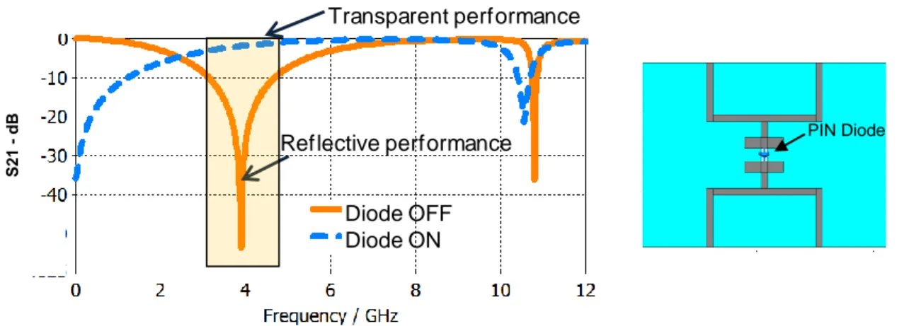
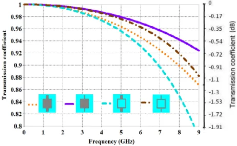
Fig. 2-3 shows a switchable FSS example with a PIN diode integrated at the center to switch the structure. The transmission coefficient (S21) is shown across a wide frequency band to clarify the switching mechanism. When the PIN diodes are biased
OFF, the squares are disconnected from each other and the diodes act as open circuits, here the FSS appears like an infinite array of squares that resonate at 3.87 GHz. When the diodes are forward biased, the squares are connected by the diodes forming an inductive series of unit cells [53]. This leads to shift the resonance to a higher frequency around 10.5 GHz. As a consequence, the FSS will be transparent at 3.87 GHz. This justifies why the FSS is switchable at 3.87 GHz and has either a transparent or a reflective performance depending on the PIN diode switching state.
Figure 2-3 Switchable frequency selective surface with PIN diodes integrated, unit cell dimensions = 14X18.7 mm Frequency (GHz) 3.0 3.5 4.0 4.5 5.0 S 2 1 - d B -60 -50 -40 -30 -20 -10 0 Diodes OFF Diodes ON Diode OFF Diode ON Reflective performance Transparent performance PIN Diode
18
2.5 PIN diodes integration in FSS
FSS are usually switched by integrating PIN diodes to the unit cells [21]. The PIN diode parameters should be selected carefully to ensure minimum influence on the unit cell performance in both the transparent and reflective state. Although different kinds and brands of PIN diodes with various specifications are available in the market, several main parameters still limit its selection process. The main parameter that should be considered is the price. This parameter is disparate and important because of the large PIN diode numbers required for the switchable FSS designs. Diodes with appropriate specifications and suitable packaging style could be expensive. There could be many types of PIN diodes suitable for each FSS design; never the less, PIN diodes with sufficient characteristics should be targeted. In the following sub sections, two main issues are discussed to illustrate the PIN diode influence on the switchable FSS unit cell.
First, PIN diodes are integrated to the unit cell and modeled with their equivalent lumped elements to investigate the most convenient equivalent elements that offer the performance closest to the ideal case.
Second, the influence of reducing the number of PIN diodes for the same FSS on the overall performance is investigated. In addition, variable capacitance values are simulated to study the impact of the equivalent circuit parasitic elements on the unit cell performance.
2.5.1 PIN diode lumped elements influence on FSS performance
Fig. 2-4 shows the FSS unit cell with mechanical switching in (a) and (b) and when integrating the PIN diode to unit cell for electrical switching in (c). The unit cell has a square shape with a vertical line between each successive unit cell, the square length is wd. The continuity of the vertical line sb, identifies whether the FSS unit cell has a reflective or transparent surface. If the vertical line sb is discontinuous and has a gap as
19
in Fig 2-4 (a), the unit cell performs as a reflective surface and does not allow the incident electromagnetic wave to penetrate. On the contrary, if the line sb is continuous between the successive unit cells, as shown in Fig. 2-4 (b), it performs as a transparent surface and allows the electromagnetic wave to propagate through the structure.
(c)
Figure 2-4 Proposed FSS structure. Dimensions (millimeters): W = 10, L = 10, Wd = 5.25, Wf = 1.5, Sb = 1.85, S = 0.5. (a) FSS with discontinuous lines in reflective state. (b) FSS with continuous lines in transparent state. (c) FSS with PIN diode.
The PIN diodes are modeled in simulation using their equivalent lumped elements RLC circuit [54]. When the PIN diode is OFF in the reversed bias, it is modeled with a series connection of the equivalent inductance and capacitance elements. When the PIN diode is ON in the forward bias, it is modeled with a resistance value of R = 1.8 Ohms. The inductance value considered is L = 0.5 nH. The most critical element that influences the FSS reflective state is the capacitance value. Therefore, two capacitance values are taken in to account. The capacitance values C = 0.001 pF and C = 0.01 pF are considered to show the impact of these two values on the switchable FSS performance. (a) (b) diode Proposed FSS unit cell sb (a) (b) diode Proposed FSS unit cell sb
20
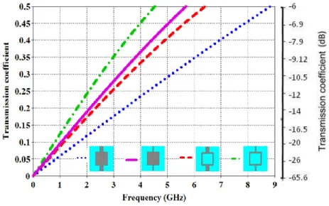
Figure 2-5 Frequency response of the proposed switchable FSS
Figure 2-5 shows the transmission coefficient of the switchable unit cell in the reflective and transparent state. The curves compare between the ideal case which has continuous and discontinuous lines and the case when the PIN diodes are integrated to the FSS. When the capacitance value is C = 0.001 pF, the maximum reflected power is at 13.88 GHz. While, when the value is C = 0.01 pF the maximum reflected power is at 12.53 GHz. In addition, the 90% reflective bandwidth for the C = 0.01 pF case is larger by 288 MHz than the C = 0.001 pF case. Table 2-1 shows the power percentages versus frequency for the transparent and reflective states. The frequency limits are minimum 90% for the reflected power. These frequencies are pointed out in Fig 2-5 around -10 dB.
According to Table 2.1, the power penetrating through the switchable FSS when it operates as a transparent surface is between 79% - 95.4%. When the FSS operates as a reflector it reflects minimum 90% of the incident power that is between 10.854 – 14.31 GHz for the C = 0.01 pF case. The minimum power limit considered in the thesis is 90% for the reflective state that is convenient for most industrial applications.
Results show that the PIN diodes with capacitance value C = 0.001 pF has a performance relative to the ideal mechanical switching case. Thus, PIN diodes with
T r an sm is sion c oe ff icie n t-dB 10.85GHz 12.33GHz 14.31GHz 15.49GHz Diode OFF Diode ON Reflective performance Transparent performance
21
similar parameters are recommended to be considered for fabrication.
Table 2-1 Switchable FSS transmitted and reflected power percentages with PIN diodes integrated
PIN diode Elements Frequency Power percentage (%)
(pF) (GHz) Transmitted Reflected
C = 0.01 10.854 79 90
C = 0.01 14.31 95.4 90
C = 0.001 12.33 85 90
C = 0.001 15.498 98 90
2.5.2 PIN diodes impact on FSS performance
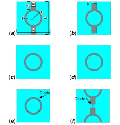
If large numbers of unit cells are desired in a switchable FSS application then the number and cost of active components will raise. Here, a novel switchable ring FSS is proposed with the need for less active components for a switchable FSS design. The switchable ring FSS presented in literature has four gaps and uses four active components to switch the unit cell [55-57]. In this section, the proposed ring FSS requires only one active element to switch the unit cell between the transparent and reflective states. Reducing the number of active components from four to one for each switchable FSS unit cell reduces the cost by 75%. In addition, it reduces the parasitic element effect that degrades the unit cell performance. Also, the proposed FSS requires no DC feed lines to bias the active elements, because they are already taken in to account in the unit-cell design. Whereas, the DC lines in the conventional ring FSS are designed on the back side of the substrate to feed the four diodes. These lines degrade the FSS performance, especially in the transparent state, as reported in [55]. Here, the ring FSS is switched by using only one gap for the first time in literature and adds enhanced features over the conventional ring FSS, results are presented and discussed to demonstrate these features.
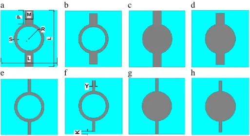
Figure 2-6 (f) shows the proposed switchable ring unit-cell with one PIN diode. This is equivalent to the mechanical switching shown in Fig. 2-6 (a) and (b), with continuous and discontinuous lines, respectively. Fig. 2-6 (e) shows the conventional switchable
22
FSS with four PIN diodes. Its equivalent mechanical switching is shown in Fig. 2-6 (c) and (d).
(a) (b)
(c) (d)
(e) (f)
Figure 2-6 Ring FSS. (a) Proposed continuous FSS. (b) Proposed discontinuous FSS. (c) Conventional ring FSS. (d) Conventional ring FSS with four gaps. (e) Switchable conventional FSS. (f) Switchable proposed FSS. Dimensions (in millimetres) are M = 1.5, L = 10, K =0.5, P = 2.475, S = 0.5, R = 2.15
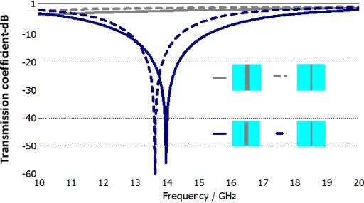
Different lumped equivalent circuits are examined to model the PIN diodes integrated to the switchable FSS unit cells. The PIN diodes are modeled as a resistor in the ON state and as a capacitor in the OFF state. Varying the resistor value in the ON state has a negligible effect on the unit cell performance. Thus, it is considered to be constant and its value is R = 1.8 Ω. When changing the value of the capacitance in the OFF state, influence is noticed on the unit cell performance. Hence, three values of capacitance are selected for the equivalent lumped elements to study their influence on the transmission coefficient. The values proposed are: C = 0.7 pF, C = 0.07 pF and C = 0.02 pF. Fig. 2-7 shows the transmission coefficient for the single active element unit cell shown in Fig 2-6 (f) when having variable capacitance values in the PIN diode OFF
L L R S M P Diode Diode K
23
state and constant resistance in the ON state. Fig. 2-8 shows the transmission coefficient with the same proposed capacitance values in the diode OFF state, but this time for the unit cell that has four PIN diodes shown in Fig 2-6 (e).
Figure 2-7 Transmission coefficient of ring FSS with single PIN diode
24
It is observed form the graphs 2-7 and 2-8 that the last four nulls are similar in the shape of the curves, but differ in terms of bandwidth and center frequencies. The main difference noticed between the two graphs is the added two nulls in Fig 2-7.
Table 2-2 and 2-3 list the percentages of the transmitted power correspondent to a minimum of 90% power reflected from the incident power. When the capacitance value is C = 0.02 pF three resonant frequencies occur at 11.94 GHz, 21.3 GHz and 25.89 GHz, as shown in Table 2-2. At the first and last resonance frequencies, the unit cell is reflective when the PIN diode is OFF and transparent when ON. At the resonance frequency 21.3 GHz, the unit-cell is reflective when the diode is ON and transparent when OFF. The same switchable states apply in Table 2-3 for the nulls at frequencies 26.64 GHz and 19.56 GHz, respectively.
2.6 Conclusion
FSSs are important periodic structures in nowadays technology due to the structure ability to control the electromagnetic waves. In this chapter an overview on FSSs has been presented. Switchable FSS adds more functionality and cost to the unit cell. The active elements added to switch the FSS influence directly the unit cell performance. Therefore, active-element price and characteristics should be compromised when designing the unit cell especially if large numbers are used. Demanded applications are the main aspect to design switchable FSSs to be appropriate for new technologies.
25
Table 2-2 Single pin diode unit cell
Diode
Elements Frequency Power percentage (%)
R (Ω) C(pF) (GHz) Transmitted Reflected 0.07 6.93 48 90 0.07 9.63 64 90 0.02 10.44 72 90 0.02 13.54 85 90 1.8 0.7 20.02 71 90 1.8 0.07 0.02 20.97 85 79 90 1.8 0.02 21.72 83 90 0.02 25.89 87 90
Table 2-3 Four pin diode unit cell
Diode
Elements Frequency Power percentage (%)
R (Ω) C (pF) (GHz) Transmitted Reflected 1.8 0.02 0.07 18.75 92 67 90 1.8 0.02 0.7 20.31 87 70 90 1.8 0.07 21.99 54 90 0.02 25.95 91.3 90 0.02 27.18 94.7 90
26
3 C
HAPTERT
HREE:
FREQUENCY SELECTIVE SURFACE UNIT CELLS3.1 Introduction
The FSS topic plays an important role in technology for its various applications. In general, the idea of using FSS is based on its structure influence on the impinging electromagnetic waves [58, 59]. A switchable FSS controls the electromagnetic wave propagation in two ways. Either it allows most of the impinging electromagnetic wave to penetrate through the structure or it reflects most of the impinging waves [59]. These two states are called transparent and reflective, respectively. In our designs, switching between the two FSS states are achieved by changing the periodicity of the FSS. This is done by controlling the gaps between the successive unit cells.
Four main variant switchable FSS geometries are introduced, planar strip, square, ring and triangle. The switchable FSSs are similar in terms of size, periodic spacing and material, but they are different in terms of geometric structure. The idea behind changing the structure geometry and keeping the other components similar is to study the influence of the geometric structure on the transmission coefficient performance in both the transparent and reflective states.
The proposed switchable FSSs are designed to work in both the resonance frequency band (f2) and the first realized frequency that can be also called the first non-resonance frequency band (f1). These two frequency bands are exploited due to the following features. First, the transparent and reflective states have compatible maximum power at the first non-resonance frequency band f1. Whereas, at the resonance frequency f2 the maximum transmitted power is not necessarily compatible in frequency with the maximum reflective power as in [34]. Second, both the reflective and transparent states have large joint bandwidth in f1 as compared to the resonance frequency f2 narrow joint bandwidth as in [31]. These features made it important to investigate the proposed designed unit cells at the non-resonance frequency f1 and at the resonance frequency bands f2 in parallel with the geometry influence on the overall performance.
27
A solid interior circular switchable FSS unit cell is taken as an example to illustrate furthermore the difference in the two operating bands f1 and f2. Fig. 3-1 (a, b) shows a circular solid interior unit cell in the reflective and transparent state. Fig. 3-2 shows the transmission coefficient for both states. At the first realized frequency band f1, both the transparent and reflective states are almost identical and have more than 90% transmitted and reflected power in both states across a joint frequency band of about 5GHz. Whereas, at the resonance frequency f2 the joint frequency could be considered between 19.8 -21.04 GHz, across a bandwidth of 1.24 GHz. In this frequency band, the reflected power is between 90%-75% and the transmitted power is more than 83% when switching between the reflective and transparent states, respectively. Never the less, a larger band could be considered for f2 but the transmitted power in this case will be less than 83%. If the selected limit is around 90% reflected power then the bandwidth is about 3.8GHz and the corresponding transmitted power will vary between 68% - 83% from the incident power. Choosing the f2 band depends on the application required. Either a wide bandwidth with high reflective power is chosen or a narrow bandwidth with high transparent power. From these results it could be concluded that the first non-resonance frequency band f1 is preferable over the resonance frequency band f2 in terms of high power accompanied with wide joint frequency bandwidth for both the reflective and transparent states.
a b
Figure 3-1 Proposed FSS unit cell structure.
a) Transparent state in the f1 case and reflective state in the f2 case b) Reflective state in the f1 case and transparent state in the f2 case
28
A
Figure 3-2 Reflective and transparent performance for f1 and f2.
3.2 Switchable frequency selective surface unit cell design
In the previous section the switchable FSS performance and differences between both the resonance and non-resonance frequency bands are explained. In this section, the concept is validated by designing four switchable FSSs: planar strip, square, ring and triangle. Each configuration has a loop design and a solid interior design with thick and thin connecting lines. Each unit cell is studied in the first non-resonance frequency band f1 and in the resonance frequency band f2. The characteristics of these two cases are examined to show the properties of each unit cell design within these frequency bands. Besides, a comparison is made between the achieved results for the proposed unit cells in both frequency bands. The comparison is presented in a table at the end of the chapter to emphasize the influence of the unit cell shape variation on the FSS properties.
Computer Simulation Technology (CST) Microwave Studio simulator is used to simulate the proposed structures. In these simulations, the incident electromagnetic wave propagation is emitted in the Z direction with normal impinging to the X - Y plane. The incident E-plane is parallel to the Y coordinate, while the H-plane is parallel to the X coordinate. The unit cells are designed on a flexible RO3003 substrate with dielectric constant of 3 and thickness of 0.13mm. This substrate is chosen due to its bending ability that is necessary to form the cylinder shape needed for the intended antenna
29 design application.
3.2.1 Planar strip switchable FSS unit-cell
In this section we consider a simple FSS structure that is a λ /2 strip lines [13]. This unit cell is included in the thesis to compare between this simple structure and other more complicated geometric structures. Fig. 3-3 shows the line shaped FSS with unit a cell dimension of L = 10 mm. The length of the gap between the successive unit cells is 1mm and two line widths are considered: Y = 0.5 mm and M = 1.5 mm.
a b c d
Figure 3-3 Conventional strip line FSS unit cell-Dimensions (mm): M=1.5, L=10, Y=.5, K=0.5, Y=0.5.
3.2.1.1 Strip line results for the resonance frequency f2
Figs. 3-4 and 3-5 show the FSS unit cell performance for both the proposed line widths. While, the transmission coefficient of the proposed unit cells in both the transparent and reflective states are shown in Fig. 3-6. The thin line unit cell has less bandwidth, and lower resonance frequency, but it has higher transmitted power as compared to the thick line. Switching is done in simulation by making the lines connected as shown in Figs. 3-3 a, c or disconnected as in Figs. 3-3 b, d. In other words, there are two designs one for the reflective state and one for the transparent state. This scenario is the ideal case where no losses occur due to active components. But it is not practically efficient because the structures have to be replaced during the switching process. The functional alternative is to use electronic switching by adding any active components in the place of the gap as discussed in chapter two. In chapter four and five, the FSS unit cells are
L
L
M Y
30
electrically switched by integrating PIN diodes to the unit cells. The FSS dimensions are constant for the unit cells presented in this chapter and only the shape of the FSSs are changed to study and compare them together at the end of the chapter. In addition, these specific dimensions are chosen to integrate the unit cells later in a reconfigurable antenna application operating in specific frequency bands.
Figure 3-4 Strip line FSS transmission coefficient for line width 1.5mm
Figure 3-5 Strip line FSS transmission coefficient for line width 0.5mm
Tr an sm is si o n co ef fi ci en t-dB Tr an sm is si o n co ef fi ci en t-dB
31
Figure 3-6 Strip line FSS transmission coefficient in the reflective and transparent states.
3.2.1.2 Strip line results for the non-resonance frequency band f1
At the non-resonance frequency, the FSS acts as a reflective surface when the unit cells are connected an in Figs. 3-3a and c and will block the incident electromagnetic wave. On the other hand, it is a transparent surface when there is a gap between the successive unit cells, as shown in Figs. 3-3b and d. It can be noticed that this configuration is opposite to the configuration in the resonance frequency band operating at f2 where Figs. 3-3a and c present the transparent state, and Figs. 3-3b and d present the reflective state.
Fig. 3-7 shows the transmission coefficient of the unit cells for both the transparent and reflective states in the first non-resonance frequency f1. Results are provided in linear and decibel scales to make it easy to compare between the unit cell performance and other unit cells in literature.
T ra n sm is si o n c o e ff ic ie n t-dB
32
Figure 3-7 Strip line FSS transmission coefficient in the reflective and transparent states at f1 3.2.2 Square switchable FSS unit-cell
Four main switchable square FSS geometries are introduced. As mentioned, the FSSs are similar in terms of size, periodic spacing and material, but they are different in terms of geometric structure. In this chapter the FSS geometries are different while the other components are similar such as the substrate used and the unit cell dimensions. This assumption is made to investigate the impact of the structure geometry on the transmission coefficient performance in both the transparent and reflective states at the resonance and non-resonance frequency bands.
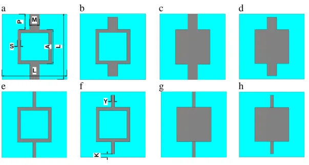
The proposed switchable square FSS unit cells are shown in figure 3-8. Different square unit cells are presented. The line P influences directly the state of the unit cell. At resonance frequency f2, if the line P is continuous between two successive unit cells, as shown in Fig. 3-8a then the FSS performs as a transparent surface. However, if the unit cell has a gap K=0.5 mm in the line P as in figure 3-8f, then the unit cell is a reflective surface and will not allow the wave to penetrate. This applies for the unit cell when operating at f2 frequency band.
Unit cells in Figs. 3-8a and b are loop switchable square FSSs with thick connecting lines in the transparent and reflective state, respectively. Figs. 3-8c and d are solid
33
interior square FSS with thick connecting lines. Figs. 3-8e and f are loop square FSS unit cell with thin connecting lines, and Figs. 3-8g and h show the solid interior square with thin connecting lines.
Figure 3-8 Square switchable FSS unit cells -Dimensions (mm): M=1.5, L=10, Y=0.5, K=0.5, P=2.375, S=0.5, A=5.25
The width of the connecting lines are chosen to be M=1.5 mm and Y=0.5 mm, these dimensions are chosen to be compatible with the unit cell dimensions. They are variable to show their influence on the transmission coefficient performance in both the reflective and transparent states. Switchable FSS unit cells presented in this chapter have the same dimensions L=10 mm and the same gap width 1 mm. In addition, the loop unit cells have similar thickness that is S=0.5 mm, and the length of the connecting lines P is the same. a M P S L L A b c d e f K Y g h