Algorithms for mathematical morphology
Texte intégral
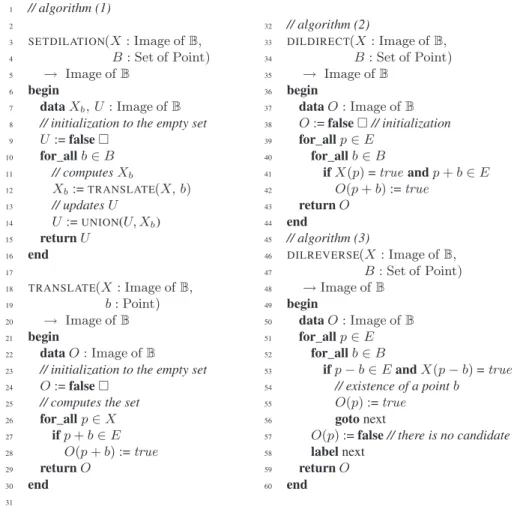
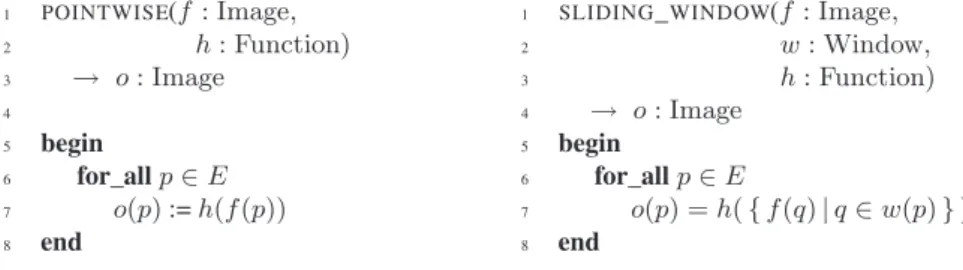
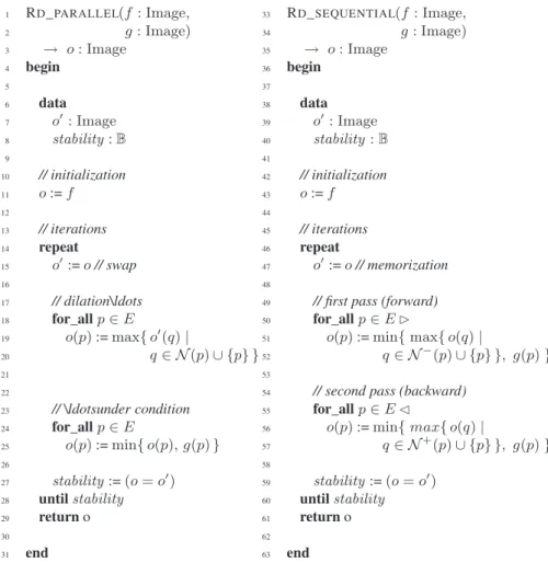
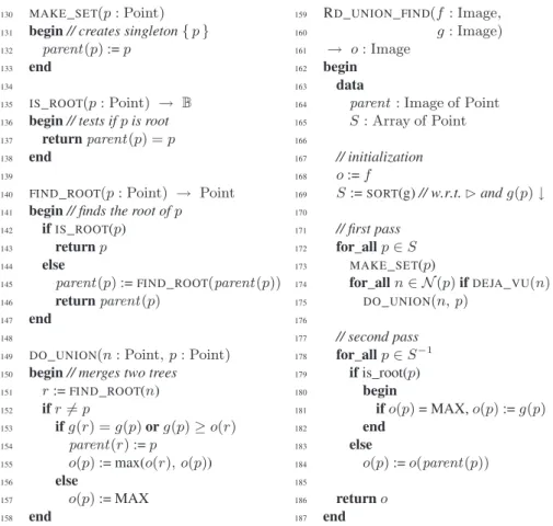
Figure


Documents relatifs
In order to support both the pupil and the interested teacher, a tool to furnish context- sensitive help for a Mathematical text written in a Braille notation would be desirable. Such
more impartial and longer lasting. Only then do we get to work on changing behaviour as a means of reinforcing the impact of the priority measures that have been taken. Most of
εἰ δὴ τὸ ὂν καὶ τὸ ἓν ταὐτὸν καὶ μία φύσις τῷ ἀκολουθεῖν ἀλλή- λοις ὥσπερ ἀρχὴ καὶ αἴτιον, ἀλλ’ οὐχ ὡς ἑνὶ λόγῳ δηλού- μενα (δι- αφέρει δὲ οὐθὲν οὐδ’ ἂν ὁμοίως
We now possess a normative model of reference for probability judgment clearly defined by the three criteria listed earlier: An agent is coherent in the Bayesian sense just adopted
The complexity of Mrs Smith’s presentation points to the challenges facing primary care providers in man- aging complex chronic diseases in older adults.. We acknowledge
The connected components of the level sets, thanks to the inclusion relation, can be organized in a tree structure, that is called the component tree.. This tree, under
We presented quasi-linear algorithms for computing W-crests and topological watersheds, which are proved to give correct results with respect to the defini- tions, and to indeed
We present an algorithm for a variant of the 3XOR problem with lists consisting of n-bit
