SOFTWARE DEFINED WIRELESS NETWORK (SDWN) FOR
INDUSTRIAL ENVIRONMENT:
CASE OF UNDERGROUND MINE
M
ÉMOIREPRÉSENTÉ
COMME EXIGENCE PARTIELLE DE LA MAÎTRISE EN INGÉNIERIE
P
ARA
LI ISSAMise en garde
La bibliothèque du Cégep de l’Abitibi-Témiscamingue et de l’Université du Québec en Abitibi-Témiscamingue (UQAT) a obtenu l’autorisation de l’auteur de ce document afin de diffuser, dans un but non lucratif, une copie de son œuvre dans Depositum, site d’archives numériques, gratuit et accessible à tous. L’auteur conserve néanmoins ses droits de propriété intellectuelle, dont son droit d’auteur, sur cette œuvre. Il est donc interdit de reproduire ou de publier en totalité ou en partie ce document sans l’autorisation de l’auteur.
Warning
The library of the Cégep de l’Abitibi-Témiscamingue and the Université du Québec en Abitibi-Témiscamingue (UQAT) obtained the permission of the author to use a copy of this document for nonprofit purposes in order to put it in the open archives Depositum, which is free and accessible to all. The author retains ownership of the copyright on this document. Neither the whole document, nor substantial extracts from it, may be printed or otherwise reproduced without the author's permission.
REMERCIEMENTS
À l'issue de la rédaction de cette recherche, j'adresse mes remerciements à toutes les personnes qui ont cru en moi et qui m’ont permis d’arriver au bout de cette thèse.
Je tiens à remercier tout d’abord mon directeur de recherche, professeur Nahi Kandil , pour m’avoir fait confiance dès le début, pour ses multiples conseils et pour sa participation scientifique.
Je suis également reconnaissant à mon codirecteur de thèse, professeur Nadir Hakem, pour m’avoir guidé et encouragé tout au long de ce travail. J'aimerais également lui dire à quel point j’ai apprécié toutes les heures qu’il a consacrées à diriger cette recherche.
Un grand merci à mes collègues Ali Nehme, Houssein Hijazi et Nour Zaarour pour la bonne ambiance de travail qui a rendu cette formation très sympathique.
TABLE DES MATIÈRES
Introduction ... 5
I. Motivation and problem : ... 5
II. Proposed solutions : ... 6
III. Methodology : ... 8
Chapitre 1 ... 10
State of the ART: ... 10
1.1. Software-Defined Network (SDN): ... 10
1.1.1. Overview: ... 10
1.1.2. Federation Of Standards: ... 11
1.1.3. SDN Architecture: ... 13
1.2. Network Function Virtualization (NFV): ... 17
1.3. Long Term Evolution (LTE): ... 22
1.3.1. LTE Architecture: ... 23
1.3.2. LTE Protocol Stack: ... 29
Chapitre 2 ... 31
Software-Defined Wireless Networks (SDWN) Platforms: ... 31
2.1. Software-Defined Wireless Networks (SDWN): ... 31
2.2. Wireless technology platforms: ... 32
2.2.1. OpenAirInterface Emulation Platform: ... 34
2.2.2. srsLTE Platforms: ... 37
2.2.3. Amarisoft Platform: ... 40
2.3. Platform Service for Software-defined 5G networks. ... 43
2.3.1. Cloud RAN (C-RAN): ... 43
Chapitre 3 ... 51
Wireless SDN architecture: ... 51
3.1. System Description: ... 52
3.2. Testbed Parameters and equipment: ... 55
3.2.1. Testbed equipment: ... 55
3.2.2. Testbed parameters: ... 55
3.3. Result and Analysis: ... 57
3.3.1. Round Trip Time measurements ... 59
3.3.2. LTE performance measurements: ... 60
Chapitre 4 ... 63
Experimental Performances Testbeds ... 63
4.1. Performance analysis of Mobile Platform. ... 63
4.1.1. Testbed deployment and configuration: ... 64
4.1.2. Results and Analysis: ... 65
4.2. Experimental performances for LTE in underground mine. ... 76
4.2.1. Environment description: ... 77
4.2.2. Testbed deployment and configuration: ... 79
4.2.3. RESULTS AND ANALYSIS: ... 82
4.2.4. Real-time Performance Evaluation: ... 92
Conclusion ... 97
L
ISTE DES FIGURESFIGURE 1: THESIS METHODOLOGY... 9
FIGURE 2: BASIC SDN COMPONENTS ... 13
FIGURE 3: SDN INTERFACES. ... 16
FIGURE 4: OPENFLOW-ENABLED SWITCH. ... 17
FIGURE 5: NETWORK VIRTUALIZATION CONCEPT ... 18
FIGURE 6: NFV ARCHITECTURE. ... 20
FIGURE 7: EVOLUTION OF THE SYSTEM ARCHITECTURE FROM GSM AND UMTS TO LTE. ... 23
FIGURE 8: LTE ARCHITECTURE. ... 24
FIGURE 9:LTE PROTOCOL STACK - CONTROL PLANE. ... 30
FIGURE 10: LTE PROTOCOL STACK - DATA PLANE. ... 30
FIGURE 11: NETWORK ARCHITECTURE OF SOFTWARE-DEFINED WIRELESS NETWORK. ... 32
FIGURE 12: USRP B210, ETTUS RESEARCH. ... 34
FIGURE 13. OPENAIRINTERFACE LTE SOFTWARE STACK ... 36
FIGURE 14: SRSLTE SOFTWARE STACK. ... 39
FIGURE 15: AMARISOFT SOFTWARE EQUIPMENT ... 40
FIGURE 16. C-RAN ARCHITECTURE BASED ON NGFI [4]. ... 46
FIGURE 17: C-RAN ARCHITECTURE USING NGFI / 3GPP TERMINOLOGIES [33]. ... 47
FIGURE 18: CLOUD-RAN DEPLOYMENT ARCHITECTURE ... 48
FIGURE 19: MOSAIC5G SCHEMATIC ARCHITECTURE [28]. ... 49
FIGURE 20: FLEXRAN PLATFORM [38]. ... 50
FIGURE 21: SDWN SYSTEM ARCHITECTURE. ... 52
FIGURE 22: SDWN SYSTEM DIAGRAM. ... 54
FIGURE 23: SDWN EXPERIMENTAL SCENARIO. ... 58
FIGURE 24: RTT OF WIRELESS NETWORKS. ... 59
FIGURE 25: LTE PERFORMANCE TEST. ... 60
FIGURE 26: THROUGHPUT RESULTS IN HETNET NETWORK. ... 61
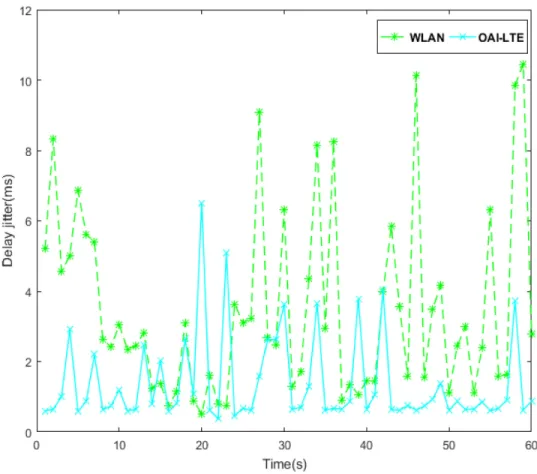
FIGURE 27: DELAY JITTER RESULTS IN HETNET NETWORK. ... 62
FIGURE 28: EXPERIMENTAL SCENARIO. ... 66
FIGURE 29: RTT RESULT OF OAI. ... 67
FIGURE 30: RTT RESULT OF AMARISOFT. ... 67
FIGURE 32: CPU USAGE AT ENB SIDE FOR DIFFERENT WIRELESS SOFTWARE WITH BW 10 MHZ. ... 69
FIGURE 33: CPU USAGE AT ENB SIDE FOR DIFFERENT WIRELESS SOFTWARE WITH BW 10 MHZ. ... 70
FIGURE 34: DELAY JITTER FOR CELLULAR PLATFORMS (BW 10 MHZ). ... 71
FIGURE 35: THROUGHPUT FOR CELLULAR PLATFORMS IN UL DIRECTION (BW 10 MHZ). ... 72
FIGURE 36: THROUGHPUT FOR CELLULAR PLATFORMS IN UL DIRECTION (BW 20 MHZ). ... 73
FIGURE 37: THROUGHPUT FOR CELLULAR PLATFORMS IN DL DIRECTION (BW 10 MHZ). ... 74
FIGURE 38: THROUGHPUT FOR CELLULAR PLATFORMS IN DL DIRECTION (BW 20 MHZ). ... 74
FIGURE 39: THROUGHPUT PERFORMANCE OBTAINED FOR USRP B210 AND AMARISOFT SDR RF USING AMARISOFT PLATFORM AND BW 10 AND 20 MHZ IN UL DIRECTION. ... 75
FIGURE 40: THROUGHPUT PERFORMANCE OBTAINED FOR USRP B210 AND AMARISOFT SDR RF USING THE AMARISOFT PLATFORM FOR BW 10 AND 20 MHZ IN DL DIRECTION. ... 76
FIGURE 41: PHOTOGRAPHY OF THE MINE GALLERY. ... 78
FIGURE 42: PHOTOGRAPHY OF THE UNIVERSITY CORRIDOR. ... 79
FIGURE 43: EXPERIMENTAL SET-UP. ... 81
FIGURE 44: MAP OF THE INDOOR CORRIDOR WITH THE LTE MEASUREMENT SETUP. ... 81
FIGURE 45: MAP OF THE MINE GALLERY WITH THE LTE MEASUREMENT SETUP... 82
FIGURE 46: COVERAGE OF LTE MOBILE PLATFORM FOR AN INDOOR SCENARIO IN TERMS OF RSSI. ... 84
FIGURE 47: COVERAGE OF LTE MOBILE PLATFORM FOR MINE SCENARIO IN TERMS OF RSSI. ... 84
FIGURE 48: SNR OF MINE AND INDOOR SCENARIOS. ... 85
FIGURE 49: RTT RESULTS OF MINE AT D= 15,30,45 AND 50 RESPECTIVELY. ... 88
FIGURE 50: RTT RESULTS OF INDOOR AT D= 15,30,45 AND 50 RESPECTIVELY. ... 89
FIGURE 51: THROUGHPUT OF MINE SCENARIO IN UL DIRECTION. ... 90
FIGURE 52: THROUGHPUT OF INDOOR SCENARIO IN UL DIRECTION. ... 91
FIGURE 53: THROUGHPUT OF MINE SCENARIO IN DL DIRECTION. ... 91
FIGURE 54: THROUGHPUT OF INDOOR SCENARIO IN DL DIRECTION. ... 92
FIGURE 55: SYSTEMS ARCHITECTURE. ... 93
FIGURE 56: LAMAQUE’S GOLD MINE MAP. ... 94
FIGURE 57: TESTBED LOCATION... 94
FIGURE 58: LTE SYSTEM CN. ... 95
L
ISTE DES TABLEAUXTABLE I: INTERFACES IN LTE ARCHITECTURE AND THEIR PURPOSE: ... 24
TABLE II. OAI MAIN PHY FEATURES:... 36
TABLE III. OAI EPC FEATURES: ... 37
TABLE IV. SRSLTE MAIN PHY FEATURES: ... 39
TABLE V. AMARISOFT MAIN PHY FEATURES: ... 41
TABLE VI. AMARISOFT EPC FEATURES: ... 42
TABLE VII. SDWN SYSTEM CONFIGURATION: ... 53
TABLE VIII. SYSTEM CONFIGURATION: ... 64
TABLE IX. SYSTEM CONFIGURATION: ... 80
TABLE X: LTE SIGNAL QUALITY: ... 83
TABLE XI: UNDERGROUND MINE PATH-LOSS EXPONENT FOR SEVERAL FREQUENCIES IN DIFFERENT LOCATIONS: ... 87
Avec le développement continu des industries minières canadiennes, l’établissement des réseaux de communications souterrains avancés et sans fil est devenu un élément essentiel du processus industriel minier et ceci pour améliorer la productivité et assurer la communication entre les mineurs. Cette étude vise à proposer un système de communication minier en procurant une architecture SDWN (Software Defined Wireless Network) basée sur la technologie de communication LTE. Dans cette étude, les plateformes les plus importantes de réseau mobile 4G ont été étudiées, configurées et testées dans deux zones différentes : un tunnel de mine souterrain et un couloir intérieur étroit. Également, une architecture mobile combinant SDWN et NFV (Network Functions Virtualization) a été réalisée.
ABSTRACT
With the continued development in the Canada mining industries, the need for an advanced and feasible underground wireless communication networks became an essential part of the industrial mining process to enhance the productivity and to provide communication between miners. This study aims to propose a mining communication system by providing a Software-Defined Wireless Network (SDWN) architecture based on LTE communication technology. In this study, the most significant 4G mobile network platforms have been studied, configured, and tested within two different areas: an underground mine tunnel and an indoor corridor of small size. Moreover, a mobile architecture that combines SDWN and Network Functions Virtualization (NFV) performed.
LISTE DES VARIABLES 3GPP Third Generation Partnership Project API Application programming interface AS Access Stratum
BBU Baseband Unit BW Bandwidth
CAPEX Capital Expenditure CN Core Network
CPRI Common Public Radio Interface C-RAN Cloud-RAN
CU Central Unit
DL Downlink
DU Distributed Unit
eMBMS Multimedia Broadcast Multicast Services eNB Evolved NodeB
EPC Evolved Packet Core EPS Evolved Packet System
ETSI European Telecommunications Standards Institute E-UTRA Evolved Universal Terrestrial Radio Access
FIB Forwarding Information Base
FPRF Field Programmable Radio Frequency
FR Frequency Range
GPP General Purpose Processor
GSM Global System for Mobile Communications GTP GPRS Tunneling Protocol
HetNet Heterogeneous Network HSS Home Subscriber Server IMS IP Multimedia Subsystem LOS line of sight
LTE Long Term Evolution MAC Medium Access Control mdev Standard Deviation MEC Mobile Edge Computing MME Mobility Management Entity MMSE Minimum Mean Square Error
mMTC massive Machine-Type Communication NaaS network as a service
NAS Non-Access Stratum
NFV Network Functions Virtualization
NFVI Network Function Virtualization Infrastructure NGFI Next Generation Fronthaul Interface
NGMN Next Generation Mobile Networks NOS Network Operating System
NR New Radio
NSA Non-standalone OAI Open-air Interface
OBSAI Open Base Station Architecture Initiative OPEX Operational Expenditure
ORI Open Radio equipment Interface PCIe PCI Express
PCRF Policy and Charging Rules Function PDCP Packet Data Convergence Protocol PDN Packets Data Networks
P-GW Packet Data Network Gateway
PL Path LOSS
PM Physical Machine QCI QoS class indicator QoS Quality of Service RAN Radio Access Network RANaaS RAN as a service RAU Radio Aggregation Unit RCC Radio Cloud Center
RF Radio Frequency
RLC Radio Link Control RRC Radio Resource Control RRH Remote Radio Head
RSRP Reference Signal Received Power RSS Radio Remote System
RSSI Received Signal Strength Indicator RTC Real-time controller
RTT Round trip time
SA Standalone
SCF Small Cell Forum
SDN Software-Defined Network SDR Software Defined Radio
SDWN Software-Defined Wireless Network S-GW Serving Gateway
SIP Session Initiation Protocol SNR Signal-to-Noise Ratio
TCAM Ternary Content-Addressable Memory TCP Transmission Control Protocol
UDP User Datagram Protocol
UE User Equipment
UMTS Universal Mobile Telecommunication System USRP Universal Software Radio Peripheral
VIM Virtualized Infrastructure Manager VM Virtual Machine
VNF Virtualized Network Function VoIP Voice over IP
INTRODUCTION
I. Motivation and problem :
Canada has one of the largest mining supply sectors for mining services, such as engineering, geotechnical, environmental, financial, and others. In total, it regroups more than 3,772 companies. In 2017, the Mining industry in Canada supplied 97 billion dollars to Canada’s Gross Domestic Product (GDP). Across the country, the industry directly employs more than 426,000 workers, and indirectly an additional 208,000. The work performed covers multiple domains, such as mineral extraction, smelting, fabrication, and manufacturing [1]. Accordingly, with the continued development in the Canada mining industries, the need for an advanced and feasible underground wireless communication networks became necessary to enhance productivity and to provide communication between miners as well as to ensure workers' safety. Thus, the wireless communication system that operates in this setting should be robust and be able to handle extreme temperatures and weather conditions, dirt, and dust, as well as shock and vibration. Often, the active mining area is continuously changing, so the network should be easy to move together with the installations in various positions around the mine. To offer maximum benefit, wireless mining communication networks should provide broadband speeds and reliable foundation to securely support multiple applications such as safety system monitoring, mobile field communications, mining management software, etc. on one cost-effective physical infrastructure.
II. Proposed solutions :
With the increasing popularity of mobile wireless communication, new services and technologies are established to meet the demands of clients. Thus, improved performance, coverage, and QoS were carried out to satisfy clients' desires by developing a robust network based on long-term evolution (LTE). This evolution of mobile broadband will continue with the new fifth-generation (5G) mobile network. The latter should be officially presented in 2020 by the Third Generation Partnership Project (3GPP) to a successor of commonly used LTE networks.
Over recent years, the emergence of open-source mobile communication software had transformed telecommunication industries from proprietary and legacy technologies to open source technologies. Besides, the mobile, open source has become an integral part of the R&D process and membership in open source communities. Thus, the latter provides much innovation happening in the space and allow extending service coverage and to connect underserved rural and remote areas.
On the other hand, the open-source availability of baseband processing and programmable frontend radio devices enable the effective implementation of different Software Defined Radio (SDR) Platforms. Based on a universal hardware platform and fully programmable communication system, SDR principle implement various radio functions over software instead of the dedicated traditional radio design. Many SDR designer chooses the General Purpose Processor (GPP) to support a baseband processing part to perform signal generation, coding/decoding, modulation/demodulation, etc. The combination of GNU Radio [2] an open-source baseband processing Platform GPP based and the Universal Software Radio Peripheral (USRP) [3] provided by Ettus research, is the leading SDR platform for research communities to interact with next generation of telecommunication architecture. Both
the research community, as well as the commercial sector, express a great interest in this Platform [4].
To extend the network level capability, we need to allocate additional spectrum resources to increase the number of users with higher data rates. We need to use the current spectrum more efficiently for the next generation of wireless communication networks [5]. Additionally, ultra-dense networks and small cells will be integrated to increase the number of users with flexible connectivity anytime, anywhere, any device (ATAWAD). Moreover, new wireless access technologies should be backward-compatible with the existing solutions to obtain the optimal network performance with faster data rates, which ultimately leads to driving the efforts toward the 5G wireless communication networks [6].
Consequently, the SDWN was developed to allow the existing mobile networks to act as operator-definable networks for further mobile applications and new solutions. Thus, SDWN presents the heterogeneous mobile wireless network efficiently to illustrate the 5G mobile network. It is composed of several wireless mobile technologies such as (Wi-Fi, LTE, etc.) and various coverage layers such as (small and macro cell-layers) over heterogeneous cellular edge networks along with the core network. Also, The SDWN topology allows operators and/or service providers to orchestrate, manage, and control SDWN networks through APIs. As long as technologies such as SDWN and NFV, network Softwarization can ensure the flexibility, modularity, and programmability that is required to establish several logical (virtual) networks, each designed for a specific use case, on top of a combined network. This study aims to enhance the mining communication system by providing an SDWN architecture based on LTE coexistence. Thus, SDWN and NFV technologies have emerged to deliver high-quality multiple performance systems with cost benefits that include several processes such as live monitoring, reconfiguration, control delegation, faster data transfer, and to handle the fulfillment of network slices. Also,
we seek to integrate an IP Multimedia Subsystem (IMS) server to offer voice over IP (VoIP) service for mobile subscribers.
III. Methodology :
To achieve our proposed solutions, we are starting our work by a full investigation of the most popular mobile communication networks that provide a full LTE protocol stack. Thus, three different mobile software were implemented in an indoor area. The three alternatives were evaluated by bringing a bunch of performance results in terms of Quality of Service (QoS) and processing resource consumptions. Subsequently, we are seeking to explore the SDWN and NFV concepts for 5G wireless networks to design an architecture based on SDWN and NFV technologies. Indeed, a Heterogeneous Network (HetNet) architecture was done based on LTE/Wi-Fi coexistence using OAI and Mosaic 5G open-source platforms, and use cases for 5G system research and platform leveraging SDN, NFV, and Mobile Edge Computing (MEC) technology provides several software components, spanning application, management, control and user plane on top of OAI platform. Then, an experimental performance test based on GPP SDR cellular platforms that provide a full LTE protocol stack, operating on frequency band 7, was conducted in real underground mine area to test our system functionality based on a subset of empirical measurements such as (Round trip time (RTT), Path-loss exponent, signal strength, coverage, and throughput etc.). Also, we compared our results to an indoor environment. Finally, we will provide a testbed scenario for our system to evaluate platform performance in the underground area. The Thesis methodology summarized in Figure 1.
STATE OF THE ART:
In this section, we present the context in which the project is carried out. First, we provide a brief study and discussion about some standards and technologies such as Software-Defined Network (SDN), Network Function Virtualization (NFV), Long Term Evolution (LTE).
1.1.
Software-Defined Network (SDN):1.1.1. Overview:
Software-defined network (SDN) technology is an agile and flexible network topology. Mainly, the SND's role is to enhance network control by allowing companies, service providers, and enterprises to interact quickly with the changing of business requirements. In SDN, a network engineer or administrator can shape traffic from a centralized control console without having to touch individual switches in the network. The SDN controller controls the routers and switches to transport network services, whether they are required, without refer to the network connections between servers and devices. This technology turned away from traditional network architecture, in which individual network devices make traffic decisions based on their configured routing tables [7].
Currently, SDN defined as a networking paradigm that decouples the control plane from the data plane, allowing for centralized control of the network along with a global network view where network applications run atop a network operating system (NOS).
The results of SDN are that it has a logically centralized network intelligence and state and an underlying infrastructure that is abstracted from network applications [8]. Moreover, proponents of SDN claim several benefits for such configurations, which include:
1) Centralized control over multi-vendor environments, 2) Automation that reduces complexity for users, 3) Higher innovation rates,
4) Increased security and network reliability 5) More granular network control,
6) Improved user experience, 7) Reduced management costs, 8) Simplified network deployments, 9) Programmable network services.
1.1.2. Federation Of Standards:
Working with a new networking architecture, like SDN, must need further standardization if it is to utilized globally. These standards are wanted for its engineering, integration, operation, and maintenance. Furthermore, systems must be produced for how SDN domains communicate with each other, additional legacy domains, and virtualized components. Many telecom executives have said that standards are critical to supporting SDN architectures [9]. However, these standards must also consider researchers and network operators to lessen the ad hoc nature of
SDN deployments. With such measures, consistent routing, security, and daily network activities can be ensured better.
Regarding certification, the current nature of SDN means that traditional network operators will require retraining and or certification to engineer and integrate SDN architectures effectively, as well as to operate and maintain them. To a certain extent, this new paradigm requires that they be software engineers first, and network operators second. Already, the ONF has established a skills certification exam, ONF-Certified SDN Engineer (OCSE-111), to certify that network operator possess the required skills for operating SDNs [9]. Currently, this exam focuses on seven domains as listed below:
1) SDN Concepts 2) Open Flow
3) SDN Architecture and Ecosystem 4) SDN Implementations and Migrations 5) Troubleshooting and Testing
6) SDN Security 7) SDN Futures
Additional research by independent sources is likely needed to validate whether this certification represents an adequate range of SDN topics for aspiring SDN operators. Nevertheless, this certification represents a starting point for organizations seeking to verify and/or certify the skills of network operators responsible for handling their organization's SDN infrastructure [10].
1.1.3. SDN Architecture:
SDN aims to produce open interfaces that facilitate the development of software that can control the connectivity provided by a collection of network resources and the flow of network traffic over them, along with possible inspection and modification of traffic that performed in the network. These primitive functions abstracted into arbitrary network services, some of which may not be presently apparent [11].
Figure 2: Basic SDN components
Figure 2 introduces the essential SDN components, with terminology similar to that from the original ONF white paper, “Software-Defined Networking: The New Norm for Networks” [12]. The initial view comprised infrastructure, control, and application layers (red text), which designated in this architecture document as data, controller, and application planes (black text).
1.1.3.1. Control Plane:
Programmability is the fundamental paradigm shift offered by SDN. It allows for an entire network of individual network devices (once programmed individually) to be processed or orchestrated as one single entity. In other words, the SDN controller, along with its interfaces, constitutes the control plane, which serves as a logically centralized intelligence having a global view of the network and the ability to reconfigure it dynamically.
As a result, this plane is often referred to as the NOS, as it allows the SDN to abstract its physical network state as a global network view to a controller instance running in the application layer [13]. Already, previous publications have attempted to identify key attributes to look for in an SDN controller. For example, Metzler et al. [14] recognize ten things to look for in a controller. These include:
1) OpenFlow Support 2) Network Virtualization 3) Network Functionality 4) Scalability 5) Performance 6) Network Programmability 7) Reliability [or Fault-Tolerance] 8) Security of the Network
9) Centralized Management and Visualization 10) Controller Vendor
1.1.3.2. SDN Interfaces:
Within the control-plane are three interfaces or APIs. Those are 1) the southbound interface,
2) the northbound interface, 3) the east-west bound interface.
Technically, these three interfaces represent standards in and of themselves. However, each of them is at various states of acceptance, development, and integration. We depict these interfaces in Figure 3 with two controllers, both serving as a NOS for their subnetwork. The northbound interface allows control programs (a.k.a. applications) to provide instructions to the controller. Through the southbound interface, the controller sends instructions and receives information from the data plane. The east-west bound interface allows for controllers to share a standard network view and to coordinate policy and protocol enforcement. Most of these interfaces currently reside in the open domain (being freely available under open source license), which has proven a significant boom in the development and expansion of SDN. It has also helped network operators to promote vendor-neutral solutions for their organizations [10].
Figure 3: SDN interfaces. 1.1.3.3. Data Plane:
The data plane or forwarding plane is usually responsible for assuring the proper transit of traffic from one ingress interface (i.e., an input port) to a suitable egress interface (i.e., an output port). Principally, this transit follows the match: action rules included in network device forwarding tables or forwarding information base (FIB). This data might also be stored in ternary content-addressable memory (TCAM) along with associated metadata, such as packet, flow, and port counters [13].
As a result, early OpenFlow [15] switches were designed with simple lookup tables (i.e., Flow Tables) to perform header matching and then execute various actions as specified in the flow table (match: action). An example of an OpenFlow-enabled switch shown in Figure 4. In this diagram, the header fields of arriving packets matched against header fields located in the TCAM or flow table. The action column indicates what to do with the packet if a match found. If no match found, then the
Figure 4: OpenFlow-enabled switch.
switch forwards the packet to the OpenFlow controller using its southbound interface to obtain new flow rules. It suffices to understand that the southbound interface refers to the protocol used by data plane elements (e.g., switches) to communicate with their controller.
1.2.
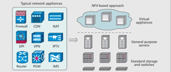
Network Function Virtualization (NFV):In recent years, the establishing of new services into traditional networks is becoming more complicated due to the difficulty to be upgraded, managed, the cost of offering the space, the energy for a variety of middle-boxes, and the lack of skilled professionals to integrate and maintain these services. In collaboration with other emerging technologies, such as SDN, Network function virtualization (NFV) was presented to resolve these problems and to increase the flexibility of network service provisioning and decrease the time to market of new services.
NFV helps the network operator to transform their infrastructure by taking the benefits of the virtualization technology to separate software instance from hardware platform, and by decoupling functionality from the location for faster networking service provisioning [16]. Thus, network virtualization is a networking medium that authorizes several service providers to dynamically create several heterogeneous virtual networks that coexist together in isolation from each other. Service providers can deploy and manage customized end-to-end services on those virtual networks for the end-users by effectively sharing and utilizing essential network resources leased from multiple infrastructure providers. Figure 5 depicts the network virtualization concept.
Based on our discussion, the main features that characterize the NFV are as follows:
• Decoupling software from hardware: The evolution of hardware and software entities are independent of each other. Also, this provides the separation between the development timelines and maintenance for each entity arises.
• Flexible network function deployment: The separation of software and hardware provide the ability to share and reallocate infrastructure resources. Thus, this helps to integrate new network services and execute various functions at a different time in several data centers in a flexible way.
• Dynamic scaling: A network operator can scale the NFV performance in multi-dynamic methods and with finer granularity according to the actual status of the network.
NFV Architecture:
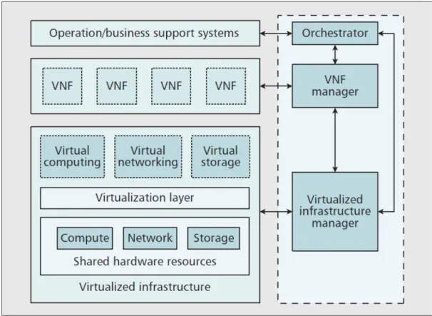
Figure 6 illustrates the architecture of NFV. Thus, the main four functional blocks are the orchestrator, VNF manager, virtualization layer, and virtualized infrastructure manager.
Figure 6: NFV architecture.
• The Virtualized Network Function (VNF)
The implementation of NFV done through a software instance called VNF that contains several portions of VMs running different processes
• The NFV orchestrator
It is responsible for the management and orchestration of VNFs network services and the virtualized hardware infrastructure to realize networking services.
It used for the management of multiple VNFs. It is responsible for the instantiation, termination, scaling, and update actions during the life cycle of a VNF instance.
• The virtualization layer
Abstracts the physical resources and anchors the VNFs to the virtualized infrastructure. It ensures that the VNF life cycle is independent of the underlying hardware platforms by offering standardized interfaces. This type of functionality typically provided in the form of virtual machines (VMs) and their hypervisors.
• The Network Function Virtualization Infrastructure (NFVI)
The background in which VNFs are running and includes physical and virtual resources, as well as the virtualization layer.
• The Virtualized Infrastructure Manager(VIM)
The VIMentity used for the management of NFVI. It is responsible for virtualizing and manage the shared hardware resources and control their communication with VNFs. Also, it manages VMs network connectivity and assigns it onto hypervisors. It also gathers information about infrastructure fault for capacity planning, optimization, and evaluates the root cause of performance issues.
• NFV Benefits a) Lower CAPEX. b) Lower OPEX. c) Greater flexibility. d) Improved scalability. e) Enhanced security.
f) Improved user experience. g) Faster provisioning.
1.3.
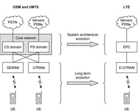
Long Term Evolution (LTE):LTE (Long Term Evolution) or E-UTRA (Evolved Universal Terrestrial Radio Access), also referred to as 4G, is a standard for wireless communication of high-speed data for mobile phones and data terminals. It designed by the Third Generation Partnership Project (3GPP), a collaboration of the national and regional telecommunications standards bodies. LTE is an upgrade version of a 3GPP system known as the Universal Mobile Telecommunication System (UMTS). The latter evolved from the Global System for Mobile Communications (GSM). The 3GPP Release 8 introduces the first specification for LTE technology. Furthermore, the Evolution of the system architecture from GSM and UMTS to LTE shown in Figure 7.
In recent years, the fast emergence of new mobile devices based on Google’s Android operating system and the Apple iPhone based on IOS, mobile phone users have overgrown worldwide. Also, with the increasing popularity of mobile wireless communication, new services and technologies are established to meet the demands of users. Thus, improved performance, coverage, QoS, and higher throughput were carried out to satisfy clients' desire by establishing a robust network based on LTE. Officially, a complete end-to-end system, which includes UE, E-UTRAN, and Core Network (EPC), is known as the Evolved packet system (EPS).
Figure 7: Evolution of the system architecture from GSM and UMTS to LTE.
1.3.1. LTE Architecture:
As shown in Figure 8, The LTE architecture contains two major components: The Radio Access Network (RAN) and the Core Network (CN), which called Evolved Universal Terrestrial Radio Access Network (E-UTRAN) and Evolved Packet Core (EPC), respectively in LTE. Evolved NodeB (eNB) or eNodeB is the E-UTRAN component and interconnect between each other via the X2 interface. The EPC is composed of four main entities: The Home Subscriber Server (HSS), the Mobility Management Entity (MME), the Packet Data Network Gateway (P-GW), the Serving Gateway (S-GW) and the Policy and Charging Rules Function (PCRF). Furthermore,
the User Equipment (UE) refers to the device used by an end-user to communicate with eNodeB, which can be a Smartphone or LTE dongle, etc.
Figure 8: LTE architecture.
TABLE I describes the interfaces used in LTE architecture and their rules.
TABLE I: Interfaces in LTE architecture and their purpose:
Interface Position and Rules
S1-MME UTRAN and MME. The reference point for the control plane protocol between E-S1-U per bearer user plane tunneling and inter eNodeB path switching Reference point between E-UTRAN and Serving GW for the
during handover.
S6a for authenticating/authorizing user access to the evolved system It enables the transfer of subscription and authentication data (AAA interface) between MME and HSS.
S11 Reference point between MME and S-GW.
mobility and if S-GW needs to connect to a non-collocated P-GW for the required PDN connectivity.
S8 between S-GW in visiting PLMN and P-GW in the Home PLMN. Inter-PLMN reference point providing user and control plane S8 is the inter-PLMN variant of S5.
Gx PCRF to Policy and Charging Enforcement Function (PCEF) in the It provides transfer of QoS policy and charging rules from PDN GW.
SGi
It is the reference point between P-GW and PDN like the Internet. PDN may be an operator external public or private packet data network or an intra-operator PDN, e.g., for the provision of an IP Multimedia Subsystem (IMS) services. This reference point corresponds to Gi for 3GPP accesses.
Uu
Enables the transferring of information by assigning radio channels to the connection between the UEs and the eNBs. The eNB, on the other hand, implements all the functions and protocols needed in order to exchange information through the radio channels and it also controls the operation of the E-UTRAN interface
X2
An optional interface established between eNBs in order to exchange control and user information when needed. However, a full mesh not mandated in an E-UTRAN network. Two types of information may typically be needed to be exchanged over X2 to drive the establishment of an X2 interface between two eNBs:
• Load- or interference-related information. • handover-related information
The components of LTE architecture are detailed in the following subsections:
1.3.1.1. E-UTRAN:
The eNB transmits and receives radio communications to all the mobiles (UEs) using the digital and analog signal processing purposes of the LTE air interface. It handles the low-level operation of UEs, by sending them signaling messages such as broadcast messages (MIB - Master Information Block), control messages (SIBs-
System Information Blocks), synchronization signals (PSS, SSS, i.e., Primary and secondary synchronization signals), and handover commands.
Each eNB connects with the EPC via the S1 interface. Also, it can be connected to nearby base stations through the X2 interface, which is mostly used for signaling and packet forwarding during handover. The eNB supports the following functions:
1) Radio Resource Management functions o Inter-cell radio resource management. o Resource block control.
o Radio admission control. o Dynamic resource allocation.
o IP header compression and encryption of user data stream.
2) Selection of an MME entity during the UE attachment procedure when no routing to an MME can be determined from the information provided by the UE.
3) Measurement and measurement reporting configuration for mobility and scheduling.
4) Routing of User Plane data towards Serving Gateway.
5) Scheduling and transmission of paging messages (originated from the MME).
6) AS security.
7) Scheduling and transmission of broadcast information (originated from the MME).
1.3.1.2. EPC:
a. HSS is the database in which we stored all the information about all UEs. It contains subscription and network performance information. The HSS is connected to the MME via the S6a interface to control the service connectivity. Also, this entity is responsible for the following user information:
1) User identification, numbering, and addressing information. 2) User security information, network access control information for
authentication and authorization.
3) User location information at the inter-system level. 4) User profile information.
HSS generates user security information for mutual authentication, communication integrity check, and ciphering.
b. MME is the central entity of the control plane within EPC. It is managing the access of the UEs through the E-UTRAN. The MME maintains the following functions:
1) Mobility Management.
2) Non-Access Stratum (NAS) signaling and security.
3) Inter core network signaling for mobility between 3GPP access networks.
4) Tracking area list management. 5) P-GW and S-GW selection.
6) Serving GPRS Support Node (SGSN) selection for handovers to 2G or 3G access networks.
7) Roaming, Authentication.
8) Bearer management functions, including dedicated bearer establishment.
c. S-GW is the data plane communication entities of the EPC. It is responsible for the packets forwarding and routing to the UE. The S-GW
is assigned to the MME entity by the S11 interface, and to the P-GW through the S5/S8 interfaces.
1) It acts as the local Mobility Anchor point for inter‐eNB handover and inter‐3GPP mobility.
2) It is in charge of users traffic routing and temporary storage of users IP packets from terminals that are in idle mode and initiates the network triggered service request procedure.
3) Accounting and QoS class indicator (QCI) granularity for inter‐ operator charging.
4) Performs user traffic routing to/from one or more P‐GWs. 5) UL and DL charging per UE, PDN, and QCI.
6) Control of use policies, control of accounting, and lawful interception.
d. P-GW is the gateway that establishes the connectivity to the external Packets Data Networks (PDN) through the SGi interface. P-GW is responsible for the following functions:
1) IP addresses Allocation to the UEs.
2) Transport level packet marking in the UL and DL.
3) Uplink and downlink service level charging, gating control, and rate enforcement.
4) Anchor point for inter‐system mobility management (between LTE and non‐3GPP networks).
5) Downlink rate enforcement based on the accumulated Maximum Bit Rate (MBRs)of the aggregate of Service Data Flows (SDFs) with the same Guaranteed Bit Rate (GBR) QCI.
e. PCRF, also is known as a policy server, is a component of EPC. A part of the policy and charging control (PCC) function that is in charge of service data flow detection and enforces the charging decisions at P-GW. The PCRF is assigned to the P-GW entity by the Gx interface. PCRF is in charge of:
1) Volume-based charging. 2) Time-based charging.
3) Volume and time-based charging. 4) Event-based charging.
1.3.2. LTE Protocol Stack:
The protocol stacks of LTE networks include the following layers: (1) Radio Resource Control (RRC),
(2) Packet Data Convergence Protocol (PDCP), (3) Radio Link Control (RLC),
(4) Medium Access Control (MAC), (5) Physical Layer (PHY).
Figure 9and Figure 10 shows the control and data plane procedures at LTE eNB, MME, UE, and the layers involved in each procedure.
Figure 9:LTE protocol stack - Control plane.
CHAPITRE 2
SOFTWARE-DEFINED WIRELESS NETWORKS (SDWN)PLATFORMS: 2.1. Software-Defined Wireless Networks (SDWN):
The SDWN was developed to allow the existing mobile networks to act as operator-definable networks for further mobile applications and new solutions [17] – [18]. Thus, SDWN presents the heterogeneous mobile wireless network efficiently to illustrate the 5G mobile network. It composed of several wireless mobile technologies such as (Wi-Fi, LTE, etc.) and various coverage layers such as (small and macro cell-layers) over heterogeneous cellular edge networks along with the core network. As shown in Figure 11, the SDWN topology allows operators and/or service providers to orchestrate, manage, and control SDWN networks through APIs [19].
Consequently, the SDWN controller provides service providers with the benefits of easier deployment of new services, the reduced management cost of various technologies, efficient operation of multi-vendor infrastructures, increased accountability, service differentiation, continuous network operation, and transparent enhancement of network operation [20].
Figure 11: Network Architecture of Software-Defined Wireless Network. 2.2. Wireless technology platforms:
This innovation has started in 1999 with an open-source telephone switch called Asterisk. Subsequently, several open-source projects have developed by several companies and research institutes, including both the hardware and software, compatible with today's standard mobile phone. Software Radio Systems, Fraunhofer FOKUS, Range Networks, Sysmocom, OpenBTS, OpenLTE, and EURECOM are some of the most prominent companies and research institutes who have been developing open-source mobile communication software projects. The combination of open-source mobile communication software with the Software Defined Radio (SDR)
provides the potential to achieve a better cellular system, about cost, time, and flexibility.
The SDR technology contains the pledge of a universal and fully programmable wireless communication system. Based on a universal hardware platform, SDR tries to implement various radio functions over software instead of the traditional radio design ideas that are depending on fixed hardware for a particular purpose. Consequently, a combination of programmable radio frequency (RF) frontend with a baseband processing platform can be constructed to form an SDR Platform.
The Universal Software Radio Peripheral (USRP) provided by Ettus research is the most famous RF frontend (see Figure 12) [21]. Moreover, to establish a baseband processing platform, General Purpose Processor (GPP) is selected by most SDR designers to execute functions like signal generation, coding/decoding, modulation/demodulation, etc. The combination of USRP RF frontend and GNU Radio [22] an open-source baseband processing Platform GPP based, is the leading SDR platform for research communities to interact with the next generation of telecommunication architecture. Furthermore, both the research community and the commercial sector are highly interested in this Platform. Thus, SDR is now recognized as the third revolution following the fixed-to-move, analog-to-digital in the communication [23].
Hence, in this section, we investigate the most popular mobile communication alternatives (namely, Amarisoft, OAI, and srsLTE) that provide a full LTE protocol stack.
Figure 12: USRP B210, Ettus Research.
2.2.1. OpenAirInterface Emulation Platform:
OpenAirInterface (OAI) is a powerful and flexible wireless technology platform based on the 4G ecosystem that contains the entire LTE protocol stack released under the AGPLv3 license, including standard-compliant implementations of the 3GPP LTE access stratum for both evolved node B (eNB) and UE and a subset of the 3GPP LTE Evolved Packet Core (EPC) protocols. OAI can be adopted as an emulation and performance evolution platform for LTE/LTE-A systems [24].
Moreover, the current development is written in C targeting both real-time and non-real-time operations and run on standard Linux-based computing equipment ranging from a simple PC to a sophisticated PC cluster or even a GPU workstation, which is distributed deployment on a local network to transmit information via the IP address.
Two unique features of the OAI platform are [25]:
1) An open-source software implementation of the 4th generation (4G) mobile cellular system that is fully compliant with the 3GPP LTE standards witch can interoperate with commercial terminals and can be used for real-time indoor/outdoor experimentation and demonstration.
2) Built-in emulation capability that can be used within the same real execution environment to transition between real experimentation and repeatable, scalable emulation. Correctly, two physical layers (PHY) emulation modes are supported, which differ in the level of detail at which PHY is realized.
As illustrated in Figure 13, the OAI LTE protocol stack includes three blocks: OAI-UE, OAI-eNB, and OAI-MME+S+P-GW as CN. The implementation of OAI eNB application comprises two primary Portable Operating System Interface (POSIX) threads, eNB_thread_rx, and eNB_thread_tx that run using the earliest deadline first scheduling [26] supported in low latency. Also, PHY, MAC, RLC, PDCP, RRC protocols are Integrated for both OAI-eNB and OAI-UE, X2AP layer was implemented in a new version for interconnecting between two eNBs. The main PHY feature summarized in TABLE II.
For real-world experimentation and validation, OAI has a custom SDR called the ExpressMiMO2 PCI Express (PCIe) board and also supported NI/Ettus Universal Software Radio Peripheral(USRP) B200 / B210, LimeSDR, and BladeRF.
Figure 13. OpenAirInterface LTE software stack
TABLE II. OAI main PHY features:
LTE releases 8.6 Compilant and a subset of release 10 Duplexing mode FDD and TDD
Tx modes 1,2 (stable), 3, 4, 5, 6, 7 (experimental) Number of antennas 2
CQI/PMI reporting Aperiodic, feedback mode 3 -0 and 3 -1 Downlink(DL) channels ALL
Uplink(UL) channels ALL
HARQ support UL and DL
Concerning the CN, the OAI includes a subset of 3GPP LTE EPC component with the Home Subscriber Server (HSS), Mobility Management Entity (MME), Serving Gateway (S-GW), Packet Data Network Gateway (P-GW) and the Non-Access Stratum (NAS) protocols. A GPRS Tunneling Protocol (GTP) for user plane is required and inserted into P-GW. Also, the OAI EPC features shown in TABLE III
TABLE III. OAI EPC features:
LTE releases 9, 10
EPC component HSS, MME, S-GW, P-GW
NAS protocol Integrity and encryption using AES and Snow3G algorithms UE handling attach, authentication, service access, radio bearer establishment GTPv1u and GTPv2c application protocols
IPv4 and IPv6 support
2.2.2. srsLTE Platforms:
srsLTE is software for SDR applications that provides a full LTE protocol stack for both srsENB (as LTE eNB) and srsUE (as LTE UE). Thus, this software has a light-weight LTE core network implementation. srsLTE was released under the AGPLv3 license and used software from OpenLTE project for some security functions and NAS
parsing. Additionally, this software is available under both Open source and commercial licenses. Also, the SRS software suite includes some custom products such as AirScope and the over-the-air LTE analysis toolbox.
The current development of srsLTE written in a C/C++ language targeting both real-time and non-real-time operations and running on standard Linux-based computing equipment ranging from a simple PC to a sophisticated cluster or even a GPU workstation. srsLTE platform supports a distributed deployment on an IP local network.
For real-world experimentation and validation, srsLTE includes support for Sidekiq M.2 SDR from Epiq Solutions. The two platforms support NI/Ettus Universal Software Radio Peripheral(USRP) B2x0/ N210/X3x0, LimeSDR, and BladeRF.
As illustrated in Figure 14, the srsLTE library provides the functions to build LTE components, including the implementation of different processing functions and physical channels such as synchronization (Sync), resampling, etc. Since the three low protocol layers (L1, L2, and L3) for eNB and UE have been implemented to the srsLTE library. Several applications examples are also integrated, including pdsch-enodeb, cell-search, cell-measurement. The main PHY features for srsLTE open source and commercial platforms are summarized in TABLE IV.
Figure 14: srsLTE software stack.
TABLE IV. srsLTE main PHY features:
srsLTE open source srsLTE commercial LTE releases subset of release 9 8 Compilant,and a 15compliant Release
Duplexing mode FDD FDD and TDD
Tx modes 1,2 , 3, 4
Number of antennas 2
CQI reporting Periodic and Aperiodic feedback support
Downlink(DL) channels ALL Uplink(UL) channels ALL
2.2.3. Amarisoft Platform:
Amarisoft is a software mobile communication company that offers 4G and newly 5G NR software running on generic hardware at the edge of a 3GPP specification. Amarisoft provides a full LTE protocol stack and supports intra-eNB, S1, X2 handovers protocols. As shown in Figure 3, this technology contains all LTE components such as EPC, eNB, NB IoT, LTE-M, evolved Multimedia Broadcast Multicast Services(eMBMS) and IP Multimedia Subsystem(IMS). At the beginning of 2019, the company announced the release of its 5G software. The new 5G portfolio includes gNodeB integrated into the non-standalone (NSA) mode and the sub-6 GHz spectrum. The 5G software will be supporting the standalone (SA) mode later [27]. Amarisoft main PHY and EPC features are shown respectively in TABLE IV, TABLE V.
Amarisoft mainly sold three solutions:
• Test and measurements: for a robust solution test equipment for 5G, LTE, and cellular equipment test. Amarisoft has two products:
AMARI LTE Callbox to test RAN devices allowing functional and performance testing. The company offers three different versions: Mini, classic and Pro.
AMARI UE Simbox: this product is to perform efficient testing of CN and eNB by simulating up to 1000+ UEs.
• Network Deployment: Amarisoft ecosystem work with a partner to build a full RAN to significant providers. This product also can be seen as network function virtualization (NFV).
• AMARI LTE NET: Amarisoft LTE Network is a Full LTE 3GPP software solution that functions as integrated components in a vast network or as SA system.
TABLE V. Amarisoft main PHY features: LTE releases 14 compilant Duplexing mode FDD and TDD
Tx modes 1 (single antenna) and 2 to 10 (Mimo 4x2 ) Downlink(DL) channels ALL
Uplink(UL) channels ALL
HARQ , CSI-RS, PAPR, PRS and Carrier Aggregation support Wideband CQI/PMI reporting
TABLE VI. Amarisoft EPC features:
LTE releases 14 compilant
EPC component HSS,MME,S-GW,P-GW,PCRF,EIR
NAS protocol NAS integrity check and encryption using the AES, Snow3G and ZUC algorithms UE handling attach, authentication, security configuration, detach, tracking area update, service access, radio bearer establishment, paging. CQI/PMI reporting Aperiodic, feedback mode 3 -0 and 3 -1
Supports several IMS servers with Rx interface several IMS servers with Rx interface
built-in dynamic ERAB setup for easy VoLTE/IMS testing IPv4 and IPv6 support
Amarisoft LTE Network is a Full LTE 3GPP software solution that functions as integrated components in a vast network or as SA system. This software runs on a standard Linux x86 based machine and has its own PCI Express SDR board. Also, this platform supports LimeSDR, PicoSDR 2x2, USRP N2x0, B2x0, and X3X0.
2.3. Platform Service for Software-defined 5G networks.
The fifth-generation New Radio (NR) requirements have been defined to serve principally using three categories: Ultra-Reliable, Low-Latency Communications (URLLC), and massive Machine-Type Communication (mMTC), and enhanced Mobile Broadband (eMBB). Thus, working with LTE to support the various requirements of new services is not sufficient. Consequently, the 3GPP started the development of a new radio access network. One of the new standards of the NR is working with a high operational frequency range (FR) between 24 and 52,6 GHz. Therefore, higher data rates can be achieved using small-cells and millimeter-wave technology. Another new standard of 5G NR [28] is the functionality splitting in terms of RAN into Baseband Unit (BBU) and Remote Radio Head (RRH), in order to present a novel mobile communication design called C-RAN. Also, the distribution of BBU functionalities between two new processing units, such as Central Unit (CU) and Distributed Unit (DU), is considered one of the significant changes. In addition, Network slicing is recognized as an essential technology for the next generation of mobile broadband. Thus, this technology enables operators to support multiple services with various specifications, across a common shared infrastructure.
In this section, we will talk about the most leading platform for Software-defined 5G network service enablers, the Mosaic 5g platform, and the C-RAN splitting functionality provided by the OAI platform.
2.3.1. Cloud RAN (C-RAN):
The main idea of CRAN is to decouple the capabilities of the base stations into a couple of pieces. It includes the RRU unit that handles the radio-frequency signal processing, and the BBU unit, which is responsible for the baseband signal processing.
Traditionally, the baseband signal processing unit is distributed into each base station. Nowadays, using C-RAN technology, the latter skills are integrated into centralized servers, known as the BBU pool. Also, the RRU controls the RF, such as analog/digital signal processing, power amplifying, and filtering. With the evolution of SDR technology, the BBU functionalities could be performed by software. Therefore, the C-RAN aim is to integrate cloud computing and virtualization technologies in order to allocate the BBU computing resources dynamically. Thus, C-RAN extends this flexibility by the abstraction of the execution environment.
Moreover, the cloud ecosystem empowers the production of new services, like RAN as a service (RANaaS), and network as a service (NaaS), such as LTEaaS, linked with the C-RAN. Thus, the centralization of the baseband operations and the effect of splitting the radio unit from the processing unit can serve two principal advantages. First, reduce the Capital Expenditure (CAPEX), and the Operational Expenditure (OPEX) due to the fewer quantity of sites, simple software upgrade, and the performance enhancement with coordinated multi-cell signal processing. Therefore, we can offer various opportunities for producing a centralized computation of the radio resources. Moreover, C-RAN can abstract the network resources by enabling the virtualization of several RAN capabilities to create multiple virtual networks or slices.
C-RAN can be achieved in two essential actions, namely [29]:
• Commoditization and Softwarization: refer to a
software implementation of network functions on top of GPPs with no or little dependency on dedicated hardware (e.g., DSP, FPGA, or ASIC). In addition, the programmability in the RF domain can be achieved with the Field Programmable Radio Frequency (FPRF) technology.
• Virtualization and Cloudification: refers to the execution of network functions on top of virtualized (and shared) computing, storage, and networking resources controlled by a cloud OS. I/O resources can be
shared among multiple physical servers, and in particular, that of radio front-end through multi-root I/O virtualization (MR-IOV).
The performance of C-RAN depends on the High-speed signal transmission between BBU and RRU over a link called fronthaul, which is different from the backhaul link that is located between the CN and the traditional eNB [30]. Currently, the most well-known standard for the fronthaul is the Common Public Radio Interface (CPRI). Indeed, there are various standards, such as the Open Radio equipment Interface (ORI) by the European Telecommunications Standards Institute (ETSI), and the Open Base Station Architecture Initiative (OBSAI). Though the CPRI standard uses fiber Optic technology to point-to-point media transmission, which is difficult to extend, and expensive in countries [31]. Thus, Telecom vendors propose the Next Generation Fronthaul Interface (NGFI) [31], [32] to overcome the lack of CPRI-based C-RAN.
1. NGFI Architecture:
NGFI is a fronthaul interface between BBU and the RRHs for the upcoming 5G network infrastructure. Unlikely the traditional C-RAN structure, in which the BBU sends I/Q samples to RRU using CPRI standard as fronthaul interface. NGFI redefines the capabilities of BBU and RRU by changing the specifications of the components. Referring to the NGFI specification introduced by China Mobile [31]. Hence the BBU becomes Radio Cloud Center (RCC), and the RRU reconsidered as Radio Remote System (RRS). Further, NGFI uses the point-to-multipoint Ethernet cable transmission instead of the point-to-point fiber optic transmission. Moreover, the Radio Aggregation Unit (RAU) is added, which interfaces with RCC and offers transport for various RRU. Figure 16 shows the C-RAN architecture based on NGFI [31].
Figure 16. C-RAN architecture based on NGFI [4]. 2. OpenAirInterface Architecture for NGFI:
Mainly OAI uses a traditional monolithic topology to run the base-station within one equipment. Nevertheless, due to the integration of NGFI requirements, OAI eNB architecture becomes more flexible in designing future networks. Thus, this provides a dynamic placement of baseband functions. Currently, OAI supports the following node functionalities:
• 3GPP eNodeB
• 3GPP eNodeB BBU [NGFI IF5] • NGFI RCC [NGFI IF4p5] • NGFI RRU [NGFI IF5] • NGFI RRU [NGFI IF4p5]
Figure 17: C-RAN architecture using NGFI / 3GPP terminologies [33]. Figure 2 depicts the C-RAN architecture mapped by the NGFI, 3GPP, Next Generation Mobile Networks (NGMN), and Small Cell Forum (SCF). It is designed for functional splits abstracted in [34]. The most important works on this subject are as follow — the Integration of the network slice feature using FlexCRAN SDN controller and the IF4P5 functional split for confirming the utility of handling network slices on-demand [35]. Moreover, a C-RAN experimental evolution in terms of latency and capacity to allow RRUs scalability using function splits and USRPs [36]. Also, in [33], the scalability of real-time synthetic networks in a software-only environment was introduced in order to decrease the signal processing complexity using the benefits of software function optimizations of the multipath channel, and signals exchange in the frequency domain.
The C-RAN contains three different links, namely the Fronthaul, the midhaul, and the backhaul, that connect the units between each other [37]. The CN connects the RCC unit through the backhaul segment within a length of 40-200 km. The RCC
communicates with RAU using the midhaul link, and the RAU attaches the RRU via the Fronthaul link within a length between 0 and 20 km. We controlled backhaul and fronthaul through S1 and IF4P5 interfaces using 1 Gigabit Ethernet ports. Figure 18 illustrates the C-RAN architecture represented by OAI. It includes OAI-EPC, RCC, and RRH.
Figure 18: Cloud-RAN Deployment Architecture
2.3.2. Mosaic5G:
Mosaic5G initiative is formed to provide an open, flexible, and agile 4G/5G experimentation platform. It aims to share an ecosystem of open-source platforms and use cases for 5G system research leveraging SDN, NFV, and multi-access edge computing (MEC) technology enablers. As a result, Mosaic5G strives to bring openness into 4G/5G for four directions among innovation, scalability, agility, and flexibility [38].
As mentioned in Figure 19, Mosaic5G spans five software components: • JOX as the service orchestrator,
• Store as the repository of applications and datasets, • LL-MEC as CN and edge controller,
• FlexRAN as the real-time radio access network (RAN) controller,
• OAI RAN and OAI CN as a 3GPP-compliant implementation of LTE/LTE-A features.
In the following section, we will provide an overview of Mosaic FlexRAN, the software that we use to improve our topology, and to apply his ability of network slicing and other features such as system monitoring.
As discussed in a few related works [39, 40], FlexRAN is the first SD-RAN platform that separates the User plane from the control plane. Moreover, it can either centralize RAN domain control logics among multiple base stations (either monolithic or disaggregated RAN) or delegate control decisions in a distributed manner. Also, Flex-RAN offers customized control functions, a hierarchical control framework with a well-defined API allowing “on-the-fly” monitoring, reconfiguration, and control delegation in the RAN domain [38].
As shown in Figure 20, the two most essential elements in FlexRAN are [38]: • Real-time controller (RTC) that enables coordinated control over multiple
RANs reveals high/low-level primitives and provision SDKs for control application.
• RAN runtime [41] that acts as a local agent controlled by RTC virtualizes the underlying RAN radio resources, pipelines the RAN service function chain, and provides SDKs enabling distributed control applications. Further, the RAN runtime can support several slice requirements (e.g., isolation) and also enhance multiplexing benefits (e.g., sharing) In terms of radio resource abstractions and modularized/customized RAN compositions for RAN slicing purpose. The FlexRAN protocol used between the RAN runtime and the RTC can provide several characteristics: provide statistics, enable reconfiguration trigger events, and delegate control.
CHAPITRE 3
WIRELESS SDN ARCHITECTURE:
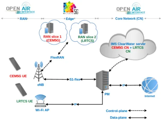
The fifth generation of mobile communications, promises to offer very high achievable data rate, very low latency, ultra-high reliability, along with supporting a wide range of new applications and use cases. In order to increase network scalability, service flexibility, and to improve mobility management in 5g wireless networks, two new concepts have emerged. Namely NFV and SDWN. In this Chapter, we designed and implemented a network architecture based on an open-source software-based LTE implementation named OAI. SDWN network technology has emerged in order to deliver high-quality multiple performance systems with cost benefits that include several processes such as live monitoring, reconfiguration, control delegation, and faster data transfer. In order to test some key enablers and features of 5G mobile networks, we provide a topology that combines SDWN and NFV technologies to handle the fulfillment of network slices by running Mosaic 5g FlexRAN software on top of the OAI platform. Moreover, Clearwater IP Multimedia Subsystem (IMS) is integrated to provide voice over IP (VoIP) service between subscribers, and a Wi-Fi Access point (AP) is added to the network in order to establish a heterogeneous wireless network (HetNet). Our results can serve as a reference for future optimization by the open-source community.
The remainder of this chapter is organized as follows. Section 1 describes our proposed topology. Testbed parameters and equipment are presented in Section 2. Section 3 presents a concrete example scenario and some results.
3.1. System Description:
The structure of our LTE/Wi-Fi wireless communication is shown in Figure 21. The experimental testbed consists of two units of commercial UE connected to one base station OAI-eNB over Uu (LTE radio interface). The UEs reach OAI- CN and IMS Clearwater server via an Ethernet cable (S1-flex) connected to OAI-eNB. In order to test network slicing in RAN, two CN, namely Cem5g CN, LRTCS CN, were virtualized in the physical machine (PM). Consequently, S1-flex allows each eNB to be connected to multiple CN and guarantees functionality and flexibility with no signal point of failure. Also, a Wi-Fi AP was connected to the physical machine. Thus the AP connects the IMS Clearwater server and reaches the internet.
Hence, network virtualization is a networking medium that authorizes several service providers to dynamically create several heterogeneous virtual networks that coexist together in isolation from each other. Service providers can deploy and manage customized end-to-end services on those virtual networks for the end-users by effectively sharing and utilizing underlying network resources leased from multiple infrastructure providers [42].
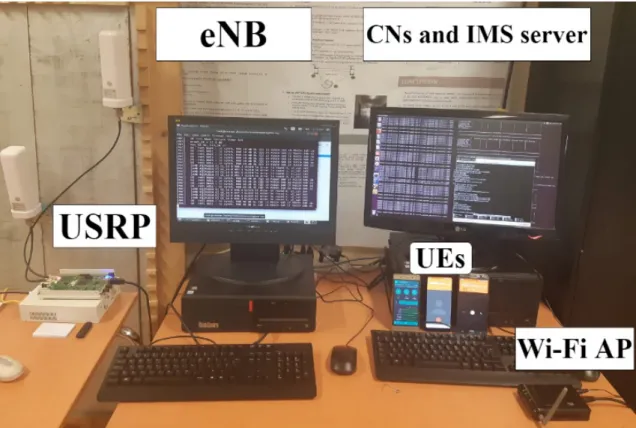
In Figure 22, The experimental scenario is described more specifically in a diagram. The two core EPC (CEM5G, LRTCS) and the IMS server were virtualized each one in a virtual machine (VM). The VMs coexist together in isolation from each other in the PM. Additionally, CEM5G EPC and LRTCS EPC take a different public land mobile network (PLMN) id, respectively (30299, 30288), and connected to eNB through S1-flex. The PC machine and usrpb210 are deployed as eNB. Also, the FlexRAN controller is running into PC and connected to eNB to enable radio resource management and network slicing.
Furthermore, UEs Connects the Wi-Fi by wireless communication provided by Wi-Fi AP, which is physically connected to the PM. To transfer audio, and video streams over IP networks, SIP protocol is used to connect the Clearwater IMS server. The main system parameters are listed in TABLE VII.
TABLE VII. SDWN SYSTEM CONFIGURATION:
Parameter Value
Computer
CPU model Intel Core i7-8700CPU @ 3.20 GHz x 6
Computer Memory 8 G
OS 64-bit Ubuntu 16.04 LTS
UE OS android
Antenna 2 TX * 2 RX
Dimensions 12.3x8.3x1.5inch
LTE
Duplex mode FDD
Transmission mode TM1 (SISO)
carrier frequency Band 7
Modulation scheme QPSK, 16-QAM, 64-QAM
WLAN Protocol IEEE 802.11n 2.4GHz
3.2. Testbed Parameters and equipment:
To identify the efficiency and adequacy of our proposed system, we must recognize the LTE GPP-based platform capabilities and classify the SDRs equipment performances as well as the 5G enabler's functions functionalities.
To do so, initially, we have to conduct various tests in terms of Resource consumptions, QoS, as well as Coverage and radio signal analysis.
3.2.1. Testbed equipment:
To succeed in our operation, we used some testbed materials in addition to some commercials smartphone as our study is for an industrial environment, so we must study the efficiency of using commercial devices with our proposed system. the following types of testing equipment are used:
• Spectrum Analyzer: Anritsu MS2661C, frequency range (9 kHz to 30 GHz). • Vector Signal Generator: Anritsu MG3692B, frequency range (250 kHz to 20
GHz).
• SAMSUNG Galaxy Note 5, A 20, A 5. • iPhone 8 plus.
• CONDOR Griffe T7.
3.2.2. Testbed parameters:
In terms of system effectiveness and capability, we use the following testbed parameters:
a. Round Trip Time test:
RTT is the Round Trip Time between TCP end-points, as seen by the TCP sender. In order to have an idea of the RTT of our link, we can ping the UE from the core

![Figure 16. C-RAN architecture based on NGFI [4].](https://thumb-eu.123doks.com/thumbv2/123doknet/7619111.234679/54.918.239.797.168.500/figure-c-ran-architecture-based-ngfi.webp)
![Figure 17: C-RAN architecture using NGFI / 3GPP terminologies [33].](https://thumb-eu.123doks.com/thumbv2/123doknet/7619111.234679/55.918.217.731.195.507/figure-c-ran-architecture-using-ngfi-gpp-terminologies.webp)