HAL Id: tel-02905264
https://pastel.archives-ouvertes.fr/tel-02905264
Submitted on 23 Jul 2020HAL is a multi-disciplinary open access
archive for the deposit and dissemination of sci-entific research documents, whether they are pub-lished or not. The documents may come from teaching and research institutions in France or abroad, or from public or private research centers.
L’archive ouverte pluridisciplinaire HAL, est destinée au dépôt et à la diffusion de documents scientifiques de niveau recherche, publiés ou non, émanant des établissements d’enseignement et de recherche français ou étrangers, des laboratoires publics ou privés.
Experimental characterization and behavior modeling of
304 stainless steel under various strain rates and
temperatures
Bin Jia
To cite this version:
Bin Jia. Experimental characterization and behavior modeling of 304 stainless steel under various strain rates and temperatures. Other [condmat.other]. Ecole nationale supérieure d’arts et métiers -ENSAM, 2019. English. �NNT : 2019ENAM0056�. �tel-02905264�
To my beloved parents for their sacrifices To my beloved sister for her support To my dear supervisors for their guidance To all my dear friends for their help
Acknowledgements
The work has been conducted in Laboratory LEM3 (Laboratoire d‘Étude des Microstructures et de Mécanique des Matériaux) and Laboratory LCFC (Laboratoire de Conception Fabrication Commande) in Metz Campus of ENSAM (École Nationale Supérieure et d‘Arts et Métiers). Here, I want to thank everyone who has helped me during the past three years.
First of all, I want to thank my thesis supervisors Alexis RUSINEK, Raphaël PESCI and Tudor BALAN, who gave me the opportunity to pursue a doctor degree. I am grateful for their dedicated support, kind guidance and invaluable advice. Without them, it is impossible for me to complete the thesis. It is really a pleasure for me to work here with them for such a long time.
I sincerely thank Prof. Francis COLLOMBET from IUT GMP de Toulouse for being the president of my PhD thesis committee. I would like to express my gratitude to the two reporters, Prof. Eric MARKIEWICZ from Université Polytechnique Hauts-de-France and Prof. Ramon ZAERA from Universidad Carlos III de Madrid, for their insightful comments and inspiring reports. I am deeply grateful to Dr Teresa FRAS from ISL Saint-Louis, for accepting the invitation and taking her precious time to attend my thesis defense. It is my honor to be able to invite such famous and knowledgeable researchers as the referees.
I would like to thank the China Scholarship Council (CSC) for providing the scholarship (Grant 201606220056) to support my study in ENSAM, France.
Special thanks to my two colleagues, Richard BERNIER and Slim BAHI. Thank you for your continual support of my experiments and the detailed discussion. You really help me a lot with my thesis. In addition, I would like to thank all my colleagues in the two labs, Anne-Laure LEBAUDY, Boris PIOTROWSKI, Christophe LESCALIER, Denis BOUSCAUD, Francois CRISTOFARI, Laurent PELTIER, Marc WARY, Patrick MOLL, Stéphanie SCHIAPPA, Pierre SIMON etc., and also my Chinese friends, Fan LI, Haitao TIAN, Jianchang ZHU, Peng WANG, Qing XIA, Tian ZHANG, Xianqiong ZHAO, Yanfeng YANG, Zhicheng HUANG, Zhaozhi LONG, as
well as my girlfriend Xuan WU, with whom I shared the unforgettable daily life memory in Metz.
I am extremely grateful to my family, my father Dongpan JIA, my mother Guanghua WANG, my sister Lin JIA and my uncle Guangzhen WANG. I grow up under your encouragement, support and sacrifice.
Last but not least, I also want to thank all the people who helped me and filled my life with laugh and happiness.
I
Table of contents
General introduction ... 1
Chapter 1 Literature review on deformation behavior of 304 ASS ... 5
1. Introduction ... 6
2. Martensitic transformation and deformation behavior of 304 ASS ... 7
2.1 Martensitic transformation in 304 ASS ... 7
2.2 Deformation behavior of 304 ASS ... 10
3. Constitutive behavior and martensitic transformation modelling in 304 ASS ... 13
3.1 Constitutive behavior modelling of metallic alloys ... 13
3.2 Constitutive modelling of martensitic transformation ... 23
4. Dynamic shear testing techniques of metallic alloys ... 27
4.1 Dynamic shear specimens ... 28
4.2 Dynamic shear testing devices ... 31
5. Perforation behavior of metallic alloys ... 35
5.1 Effect of several parameters on perforation behavior of thin plates ... 36
5.2 Perforation behavior of thin plates under various temperatures ... 39
Conclusion ... 41
References ... 42
Chapter 2 Thermo-viscoplastic behavior of 304 ASS ... 57
1. Introduction ... 58
2. Material behavior and set-up description ... 59
2.1 Material and specimen ... 59
II
3. Calibration and heat transfer modelling of the heating furnace/cooling device ... 62
4. Experimental results and discussion ... 68
4.1 True stress-true strain relations of 304 ASS ... 68
4.2 Strain rate and temperature sensitivity of 304 ASS... 72
5. Thermo-viscoplastic behavior modelling of 304 ASS ... 75
5.1 The extended R-K constitutive equation ... 80
5.2 Comparison between experimental and predicted flow stress for 304 ASS ... 84
6. Conclusion ... 88
References ... 89
Chapter 3 A new shear testing technique for extreme high strain rates ... 95
1. Introduction ... 96
2. The new shear specimen ... 97
3. Preliminary experimental results ... 99
4. Numerical analysis of the new shear specimen ... 103
4.1 Validity of the pulse signals in dynamic shear tests ... 103
4.2 Analysis of stress state in specimen shear zone ... 108
4.3 Determination of shear stress-shear strain relations ... 114
5. Shear stress-shear strain relations of 304 ASS ... 121
6. Conclusion ... 127
Reference ... 128
Chapter 4 Perforation behavior of 304 ASS ... 131
1. Introduction ... 132
2. Material and setup description ... 133
III
2.2 Projectile and target description ... 134
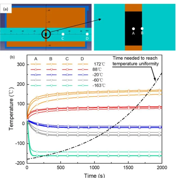
2.3 Thermal chamber/cooling device for high/low temperature perforation tests 137 3. Reliability verification of the cooling device ... 140
3.1 Temperature evolution and distribution along the diagonal line of the target 141 3.2 Calibration and heat transfer modelling ... 143
4. Influence of testing temperature on the perforation process ... 147
4.1 Effect of temperature on failure mode ... 147
4.2 Effect of temperature on the ballistic curves ... 149
4.3 Effect of temperature on the energy absorption capacity ... 151
5. X-ray diffraction analysis of perforated specimens ... 155
6. Numerical simulations of the perforation process ... 159
6.1 Numerical model description ... 159
6.2 Numerical results of the ballistic curves and the fracture patterns ... 165
7. Conclusions ... 171
References ... 172
Conclusions ... 177
1
General introduction
As a representative of Transformation Induced Plasticity (TRIP) steels, 304 austenitic stainless steel (ASS) has a unique combination of high strength and high ductility. Its beneficial mechanical properties come from Strain-Induced Martensitic Transformation (SIMT), which means that upon plastic deformation the initial austenite phase (γ) transforms into stable martensite phase (α'); thus, both improved
work hardening rate and significantly enhanced ductility can be achieved.
304 ASS is widely used in many engineering areas such as chemical, transportation, nuclear and aerospace industries. During working and manufacturing process, it may undergo deformation over a wide range of strain rates and temperatures; therefore, much work has been done to investigate the effects of these two parameters on the deformation behavior. The main conclusions are listed:
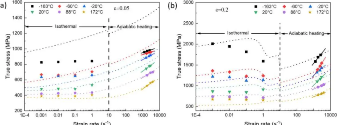
- Compared to the conventional metallic alloys whose deformation is dominated by dislocation slip, the temperature sensitivity of 304 ASS is strongly affected by the SIMT effect. At temperatures below 𝑀𝑑, the temperature below which martensitic transformation occurs automatically or can be triggered by plastic deformation, the stress-strain curves of 304 ASS exhibit an S-shape and a second hardening phenomenon is often observed. With decreasing temperature, the flow stress increases continuously and the second hardening phenomenon becomes more obvious. At temperatures above 𝑀𝑑, the deformation mechanism of 304 ASS changes into dislocation glide. Therefore, with increasing temperature, the strength of 304 ASS decreases without the second hardening phenomenon.
- The strain rate sensitivity of 304 stainless steel is also different from the commonly used metallic alloys. On the one hand, the transformation process is inhibited by adiabatic heating effect at high strain rates and the corresponding strain hardening rate decreases. On the other hand, due to the viscous drag effect under dynamic strain rates, a pronounced strain rate sensitivity is often observed.
2
Combining effects of strain rate on both dislocation slip and martensitic transformation, either positive or negative strain rate sensitivity is often observed.
Although the deformation behavior of 304 ASS has been studied massively, several scientific and engineering issues remain unclear:
- Previous studies mainly focused on quasi-static deformation at various temperatures or dynamic tests at room temperature. While the combined effects of temperature and dynamic loading on mechanical properties of 304 ASS are frequently encountered, the corresponding deformation behavior is not clearly understood.
- Due to the unique combination of elevated strength and high ductility, 304 ASS is widely used in energy absorption and crashworthiness areas. It may also be subjected to high strain rates (≥104 s-1) during processes such as high speed
machining and ballistic impact especially under various temperatures. Few works for ballistic impact can be found in literature: the corresponding deformation behavior and the failure mechanisms remain imprecise.
This thesis aims to study the deformation behavior of 304 ASS under different strain rates and temperatures, with special focuses on the two issues mentioned above. The objective is divided into several parts. The first goal is to obtain the thermo-viscoplastic behavior of 304 ASS under various strain rates and temperatures both experimentally and by constitutive modelling. The second is to study the deformation behavior of 304 ASS under extreme high strain rates with a newly developed shear specimen. Finally, the perforation behavior of 304 ASS under various velocities and temperatures is investigated experimentally and numerical simulations are conducted and compared to the experimental results.
Chapter 1 is based on a literature review on the deformation behavior of 304 ASS under different strain rates and temperatures. The focus is made on four parts:
3
first, martensitic transformation and deformation behavior of 304 ASS under different strain rates and temperatures; second, constitutive behavior and martensitic transformation modelling of 304 ASS; third, several testing techniques for shear behavior study under extremely high strain rates; fourth, impact behavior of metallic alloys under various deformation conditions.
Chapter 2 presents the thermo-viscoplastic behavior study of 304 ASS. First, a home-designed heating furnace/cooling device is coupled to the conventional SHPB apparatus and the equipment reliability is verified. Compression tests of 304 ASS are conducted: the influence of temperature and strain rate on the deformation behavior of 304 ASS is presented and discussed. Then, an extension of the Rusinek-Klepaczko (RK) constitutive model considering martensitic transformation is chosen to describe the temperature and strain rate dependent deformation behavior of 304 ASS.
In chapter 3, a new shear specimen is designed and validated for dynamic shear testing of bulk materials using the conventional Split Hopkinson Pressure Bar (SHPB) system. First, the newly designed shear specimen and the corresponding shear testing technique are introduced. Then, this method is used to test the shear behavior of 304 ASS: the experimental results are presented and discussed. In the third section, the experimental stress-strain curves are compared to finite element analysis (FEA) and the stress distribution inside the shear zones are analyzed.
Chapter 4 is dedicated to the perforation behavior of 304 ASS at various velocities and temperatures. An original cooling device is developed to test the material behavior at low temperatures, and its reliability is verified. Then, ballistic impact tests are carried out under different temperatures and the experimental results are discussed, including the measurement of the volume fraction of induced martensite in perforated specimens (X-ray diffraction measurements), to explain the improved energy absorption capacity at low temperatures. In addition, numerical
4
simulations of perforation tests are carried out with the extended RK model introduced in chapter 2 and compared to the experimental results.
The main conclusions are summarized in the last part of the manuscript: the original scientific contribution is highlighted and some perspectives for future work are proposed.
5
Chapter 1 Literature review on deformation
behavior of 304 ASS
6
1. Introduction
304 ASS is the most widely stainless steel in the world due to its unique combination of moderate strength and high ductility, Fig. 1.1. The improved mechanical properties come from the SIMT effect, Fig. 1.2. During the working and manufacturing processes, 304 ASS is frequently subjected to various deformation conditions such as strain rate, temperature and stress state. Therefore, it is interesting and necessary to study the effects of those parameters on the deformation behavior of 304 ASS.
Fig. 1.1. Overview of typical strength-ductility profiles of different types of steels [1].
Fig. 1.2. Microstructure evolution of 304 ASS during quasi-static tension test [2].
In the past few decades, much work has been done to study the deformation and martensitic transformation behavior of 304 ASS. Many progressive conclusions
7
mainly about the deformation mechanism, microstructure evolution and thermo-viscoplastic behavior modelling, have been drawn. However, as is presented in the introduction part, several questions remain unclear and further researches are needed. In order to start research in this area, deformation behavior of 304 ASS under different strain rates and temperatures is reviewed in this chapter.
The literature review consists of four parts introducing the effects of temperature and strain rate on the martensitic transformation and deformation behavior of 304 ASS; constitutive behavior and martensitic transformation modelling; techniques for shear testing under extreme high strain rates and ballistic impact behavior of metallic alloys under different deformation conditions.
2.
Martensitic
transformation
and
deformation behavior of 304 ASS
2.1 Martensitic transformation in 304 ASS
Martensitic transformation is affected by several parameters including temperature [3], chemical composition [4], stress state [5], grain size [6] and strain rate [7]. Especially, much work has been done to investigate the temperature and strain rate’s effects.
The effect of temperature on the martensitic transformation is shown in Fig. 1.3. 𝑀𝑠 is the temperature below which the Gibbs free energy between the austenite phase (𝛾) and the martensite phase (𝛼′), ∆𝐺𝑇<𝑀
𝑠
𝛾→𝛼′, is high enough for martensitic transformation to occur spontaneously. At temperatures 𝑀𝑠 < 𝑇 < 𝑀𝑑 , the ∆𝐺𝑀𝛾→𝛼𝑠<𝑇<𝑀′ 𝑑 is too small to trigger the martensitic transformation and an additional mechanical driving force 𝑈′ is needed:
8
∆𝐺𝑀𝛾→𝛼𝑠<𝑇<𝑀′ 𝑑 + 𝑈′= ∆𝐺 𝑀𝑠
𝛾→𝛼′
Eq. 1.1 At temperatures 𝑀𝑠 < 𝑇 < 𝑀𝑠𝜎, the mechanical driving force needed is smaller than the yield stress of the austenite phase and martensitic transformation takes place during the elastic deformation process of the austenite phase. With increasing temperature 𝑀𝑠𝜎 < 𝑇 < 𝑇
0, the driving force to induce martensitic transformation exceeds the yield stress of the austenite phase and plastic deformation of austenite phase is required to supply the mechanical driving force. At temperatures 𝑇0 < 𝑇 < 𝑀𝑑, the Gibbs free energy of the two phases reverses and martensitic transformation takes place with an external mechanical driving force by 𝑈′> ∆𝐺
𝑇0<𝑇<𝑀𝑑
𝛾→𝛼′
. With further increase of temperature, the mechanical driving force needed exceeds the flow stress of austenite phase and martensitic transformation does not occur anymore. The corresponding deformation mechanism changes into twinning or dislocation slip [1]. Therefore, with increasing temperature, martensitic transformation in 304 ASS is gradually suppressed, both the transformation rate and the final martensite volume fraction decrease, Fig. 1.4 [2].
Fig. 1.3. Effect of temperature on the Gibbs free energy of both martensite and austenite phases [10,11].
9
Fig. 1.4. Martensitic volume fraction as a function of equivalent plastic strain under various temperatures [9].
Strain rate is another parameter that affects SIMT. It is both beneficial and harmful to the martensitic transformation: on one hand, martensite nucleates at shear band intersections and the number of intersections increases with increasing strain rate. Hence, more martensite forms at high strain rates and small strains. On the other hand, at dynamic strain rates and large strains, the adiabatic heating effect becomes obvious and martensitic transformation is strongly inhibited.
Hecker et al. [12] and Murr et al. [13] performed tension tests at both low (10-3 s-1) and high (103 s-1) strain rates to study martensitic transformation behavior
in 304 ASS. They found that martensite volume fraction at 103 s-1 is obviously lower
than that at 10-3 s-1 at large strains, Fig. 1.5. A similar phenomenon was observed by
10
Fig. 1.5. Martensite fraction during tests at room temperature in balanced biaxial tension at high (103 s-1) and low (10-3 s-1) strain rates [12].
2.2 Deformation behavior of 304 ASS
Deformation mechanism of 304 ASS is a combination of martensitic transformation and dislocation slip or even twins [15]. But the contribution of each aspect varies significantly at different strain rates and temperatures. Therefore, the evolution of flow stress with strain rates and temperatures is different from the commonly used metallic alloys.
Concerning the effect of temperature on the deformation behavior of 304 ASS, it can be divided into two regions: 𝑇 < 𝑀𝑑 and 𝑇 ≥ 𝑀𝑑. At temperatures below 𝑀𝑑, the stress-strain curves exhibit an S-shape and a second hardening phenomenon. This is caused by SIMT. With decreasing temperature, the flow stress increases continuously, and the nonlinearity phenomenon becomes more obvious. At temperatures above 𝑀𝑑, dislocation slip becomes the main deformation mechanism. According to thermally activated dislocation theory, the slip obstacles can be overcome by gliding dislocations more easily at higher temperatures due to the
11
assistance of thermal energy [3]. Therefore, with increasing temperature, the strength of 304 ASS decreases without the second hardening behavior.
Byun et al. [4] studied quasi-static tension behavior of 3 kinds of ASS including the type 304 at temperatures ranging from -150°C to 450°C. As shown in Fig. 1.6, both the yield stress and the ultimate tensile strength decrease with increasing temperature, and the best ductility peaked at 20°C. At temperatures below 20°C, the typical second hardening phenomenon accompanied by martensitic transformation was observed. Hamada et al. [1] investigated deformation behavior of 201 and 201L austenite stainless steel at temperatures ranging from -80°C to 200°C and obtained similar results: increasing flow stress with decreasing temperature. The maximum elongation value was obtained at 50°C, a temperature around which martensitic transformation was suppressed but intense mechanical twins formed.
Fig. 1.6. Temperature dependence of engineering stress-strain curves for 304 stainless steel [3].
12
20°C and found both the flow stress and the strain hardening rate increased with decreasing temperature. In addition, because of the thermally induced martensitic transformation before tensile testing, the yield stress at -253°C and -196°C was significantly higher than the other temperatures.
Affected by SIMT, strain rate sensitivity of 304 stainless steel is also different from the commonly used steels whose deformation is dominated by dislocation slip.
At the initial stage of deformation, flow stress of 304 stainless steel increases with increasing strain rate as the time available for a dislocation to wait in front of an obstacle for the additional thermal energy is reduced. Also, the positive strain rate sensitivity at small strains was reported to be partly caused by higher martensite fraction at higher strain rates by Hecker et al. [12] and Murr et al. [13].
However, when it comes to large strains strengthening effect originated from martensitic transformation is inhabited by adiabatic heating at high strain rates and the corresponding strain hardening rate decreases. Combining strain rate’s effect on both dislocation slip and martensitic transformation, either positive [14,18] or negative [19,20] strain rate sensitivity of 304 ASS was observed.
Lichtenfeld et al. [7] investigated the tension behavior of 304L stainless steel at room temperature. With the strain rates increasing from 10-4 s-1 to 400 s-1, the flow
stress declined first (from 10-4 s-1 to 10-2 s-1) and then began to increase (from 10-1
s-1 to 400 s-1). In addition, Ishikawa and Tanimura [21] found 304N stainless steel
showed a positive strain rate sensitivity at room temperature but it changed into negative when tested at -83°C, Fig. 1.7.
13
Fig. 1.7. The flow stress of 304N at constant strain vs strain rate at (a) 83 K and (b) 296 K [21].
3. Constitutive behavior and martensitic
transformation modelling in 304 ASS
3.1 Constitutive behavior modelling of metallic alloys
The constitutive models are divided into two categories:
- Phenomenological models. They provide a description of flow stress based on empirical observations and are commonly made up of some mathematical functions [22]. They are simple and have a limited number of material parameters. However, they do not have any physical basis and are usually used in limited deformation conditions (for example limited range of strain rates and temperatures).
- Physical models. They are built according to physical theories such as thermally activated dislocation. Compared to phenomenological models, they can give an accurate deformation behavior description over a wide range of deformation conditions. But the models are usually complicated and a large number of tests are needed to define material constants.
14
Phenomenological models
Phenomenological models, including Johnson-Cook (JC) model [23], Khan-Huang (KH) model [24], Khan-Khan-Huang-Liang (KHL) model [25–27], and Arrhenius equation [28,29], are widely used in numerical simulations. The common feature of these models is that they can be expressed as functions of several deformation parameters’ effects on the flow stress:
𝜎 = 𝜎(𝜀, 𝜀,̇ 𝑇, 𝜂, 𝜃̅) Eq. 1.2
⚫
Johnson-Cook (J-C) model
Johnson-Cook (J-C) model is commonly used for many kinds of materials over a wide range of strain rates and temperatures. It is expressed as:
𝜎 = (𝐴 + 𝐵𝜀𝑛)(1 + 𝐶𝑙𝑛𝜀̇∗)(𝑎 − 𝑇∗𝑚) Eq. 1.3 where 𝜎 is the flow stress, 𝜀 is the equivalent plastic strain, 𝐴 is the yield stress at reference strain rate and temperature, 𝐵 is the strain hardening coefficient, 𝑛 is the strain hardening exponent, 𝜀̇∗ = 𝜀̇
𝜀̇𝑟𝑒𝑓 is the dimensionless strain rate and 𝑇
∗ = (𝑇−𝑇𝑟)
(𝑇𝑚−𝑇𝑟) is the homologous temperature. 𝑇 is the absolute temperature, 𝑇𝑚 is the melting temperature and 𝑇𝑟 is the reference temperature.
The three items in the equation describe the strain hardening effect, strain rate sensitivity and thermal softening effect, respectively. In addition, the three effects are assumed to be independent of each other.
J-C model is widely used because it is simple to implement and the parameters are easy to be obtained with a limited number of tests. However, it regards the mechanical properties of materials as a simple multiplication of strain, strain rate and temperature and ignores the coupling effects between them. Therefore, some researchers made modifications to the original J-C model and gave a more accurate
15
deformation behavior description [5-8].
⚫
Khan-Huang (K-H) model and Khan-Huang-Liang
(K-H-L) model
Khan-Huang (K-H) model was developed by Khan and Huang [9] in 1992 to model deformation behavior of Al 1100 alloys. It is given as:
𝜎 = 𝑔1(𝜀)𝑔2(𝜀̇) Eq. 1.4 𝑔1(𝜀) = 𝜎0 + 𝐸∞𝜀 − 𝑎𝑒−𝛼𝜀 Eq. 1.5 𝑔1(𝜀)𝑔2(𝜀̇) = [1 − 𝑙𝑛(𝜀̇) 𝑙𝑛(𝐷𝑚𝑎𝑥𝑝 )] 𝑛 Eq. 1.6
where 𝑔1(𝜀) characterizes the flow stress versus strain at reference strain rate, and 𝑔2(𝜀̇) describes the strain rate hardening effect. 𝜎, 𝜀, 𝜀̇ and 𝐷𝑚𝑎𝑥𝑝 are the flow stress, the equivalent plastic strain, the strain rate and the maximum strain rate the material experienced during the testing process, respectively. 𝑛, 𝐸∞, 𝜎0, 𝑎 and 𝛼 are material constants need to be determined.
It is obvious that K-H model does not take temperature’s effect into consideration. In order to give a better prediction of strain hardening behavior of materials, Khan, Huang and Liang added the coupling thermal effect of strain and strain rate to the original K-H model and developed the Khan-Huang-Liang (K-H-L) model:
𝜎 = [𝐴 + 𝐵 (1 − 𝑙𝑛𝜀̇ 𝑙𝑛𝐷0𝑝)
𝑛
𝜀𝑘] (1 − 𝑇∗𝑚)𝑒𝑥𝑝(𝑐𝑙𝑛𝜀̇) Eq. 1.7 where 𝐴 , 𝐵 , 𝑛 , 𝑘 , 𝑐 , and 𝑚 are material constants; 𝑇∗ = (𝑇−𝑇𝑟)
(𝑇𝑚−𝑇𝑟) is the
homologous temperature (𝑇 is the testing temperature, 𝑇𝑚 is the melting temperature and 𝑇𝑟 is the reference temperature). It is obvious that the coupling
16
effect between strain and strain rate on strain hardening behavior of materials is included in the model.
For Ti-6Al-4V alloy, a comparison between experiments and the predicted results by J-C model and K-H-L model is shown in Fig. 1.8. The K-H-L model gives a slightly better agreement with experimental data than the J-C model.
Fig. 1.8. True stress-true strain curves of Ti-6Al-4V alloy with correlations using J-C and K-H-L models [10].
⚫
Arrhenius equation
Arrhenius equation is widely used to describe flow stress’s dependence on strain rate at elevated temperatures [11]. The effects of strain rate and temperature on the deformation behavior of materials can be described by the Zener-Hollomon parameter in an exponent-type equation [12,13].
𝜀̇ = 𝐴𝐹(𝜎)𝑒𝑥𝑝 (−𝑅𝑇)𝑄 Eq. 1.8 𝑍 = 𝜀̇𝑒𝑥𝑝 (𝑄𝑅𝑇 ) Eq. 1.9 𝐹(𝜎) = [𝑠𝑖𝑛ℎ(𝛼𝜎)]𝑛 Eq. 1.10
17
where 𝜀̇ is the strain rate, 𝑅 is the universal gas constant, 𝑇 is the absolute temperature, 𝑄 is the activation energy for deformation behavior, σ is the flow stress, 𝐴, 𝛼 and 𝑛 are material constants.
According to the three equations above, the flow stress can be written as,
𝜎 =𝛼 𝑙𝑛 [(1 𝐴)𝑍 1 𝑛 + √(𝑍𝐴) 2 𝑛 + 1] Eq. 1.11
It is clear that the effect of strain on the deformation behavior of materials is not included in the Arrhenius equation. Therefore, Lin et al. [14] modified the model by considering strain rate and strain, then used it to describe flow stress of 42CrMo steel over a wide range of strain rates and temperatures. They expressed 𝑄, 𝑛, 𝐴 and 𝛼 as polynomial functions of strain:
𝑄 = 𝐵0+ 𝐵1𝜀 + 𝐵2𝜀2+ 𝐵3𝜀3+ 𝐵4𝜀4+ 𝐵5𝜀5 Eq. 1.12 𝑛 = 𝐶0+ 𝐶1𝜀 + 𝐶2𝜀2 + 𝐶3𝜀3+ 𝐶4𝜀4+ 𝐶5𝜀5 Eq. 1.13 𝐴 = 𝑒𝑥𝑝(𝐷0+ 𝐷1𝜀 + 𝐷2𝜀2+ 𝐷3𝜀3+ 𝐷4𝜀4+ 𝐷5𝜀5) Eq. 1.14 𝛼 = 𝐸0+ 𝐸1𝜀 + 𝐸2𝜀2+ 𝐸3𝜀3+ 𝐸4𝜀4+ 𝐸5𝜀5 Eq. 1.15 Two comparisons between experiments and modeling results are shown in Fig. 1.9. It is clear that experiments and simulations are highly consistent with each other.
18
Fig. 1.9. Comparisons between experiments and modelling results of 42CrMo steel at strain rates (a) 0.01 s-1 and (b) 50 s-1 [14].
Physical models
An obvious drawback of phenomenological models is that they are obtained by fitting experimental data and do not include any deformation mechanism. They may work well under common conditions, but when it comes to the extreme conditions (such as extreme high strain rates and temperatures), they are not able to give an accurate description anymore. Therefore, physical models based on deformation mechanisms such as dislocation dynamics and thermal activation seem to be more reliable. Until now, many physical models such as Zerilli-Armstrong (Z-A) model [36], Bonder-Partom (B-P) model [37] and Rusinek-Klepaczko (R-K) model [38] have been developed.
⚫
Zerilli-Armstrong (Z-A) model
Zerilli-Armstrong (Z-A) model is developed based on dislocation mechanism and often gives a good description of deformation behavior under different loading conditions. It considers the effects of strain hardening, strain rate hardening and thermal softening on deformation behavior of materials, and is made up of two parts, thermal component and athermal component,
19
𝜎 = 𝜎𝛼+ 𝜎𝑡ℎ Eq. 1.16 where 𝜎𝛼 is the athermal flow stress, 𝜎𝑡ℎ is the thermal flow stress.
𝜎𝑡ℎ= 𝑀∆𝐺0𝑒 −𝛽𝑇
𝐴𝑏 Eq. 1.17
𝛽 = −𝐶3+ 𝐶4𝑙𝑛𝜀̇ Eq. 1.18 where 𝑀 is the direction factor, ∆𝐺0 is the free energy of thermal activation at 0 K, 𝑏 is the burger vector, 𝛽 is a parameter related to strain and strain rate.
For BCC metal, 𝐴 is a material constant. But for FCC metal, 𝐴 is regarded as √𝜀 . Therefore, the thermal flow stresses for BCC and FCC metal are written separately as
𝜎𝑡ℎ = 𝐶1exp(−𝐶3𝑇 + 𝐶4𝑇𝑙𝑛𝜀̇) Eq. 1.19 𝜎𝑡ℎ = 𝐶2𝜀
1
2exp(−𝐶3𝑇 + 𝐶4𝑇𝑙𝑛𝜀̇) Eq. 1.20 Combining the athermal and thermal parts, the equations for FCC and BCC metals are
𝜎 = 𝐶0+ 𝐶1𝑒𝑥𝑝(−𝐶3𝑇 + 𝐶4𝑇𝑙𝑛𝜀̇) + 𝐶5𝜀𝑛 Eq. 1.21 𝜎 = 𝐶0+ 𝐶2𝜀12𝑒𝑥𝑝(−𝐶3𝑇 + 𝐶4𝑇𝑙𝑛𝜀̇) Eq. 1.22 where 𝐶0, 𝐶1, 𝐶2, 𝐶3, 𝐶4, 𝐶5 and 𝑛 are material constants.
It can be seen from the two equations that the strain hardening rate of BCC materials is not affected by strain rate or temperature; while for FCC materials, the strain hardening rate is strongly affected by the two parameters. In fact, the coupling effects between strain, strain rate and temperature should be considered in a more effective constitutive way. Therefore, some researchers made several modifications to the Z-A model [15-19].
20
⚫
Bodner-Parton (B-P) model
In 1975, Bodner and Parton [20] proposed a model to describe the deformation behavior of materials under large deformation and arbitrary loading histories. The model divides the total deformation into elastic and plastic components, which are functions of strain state variables at all deformation stages. The model is given as
𝜀̇𝑝 = 2𝜎 √3|𝜎|𝐷0exp [− ( 𝑛 + 1 2𝑛 ) ( 𝑍 𝜎) 2𝑛 ] Eq. 1.23 𝑍 = 𝑍1+ (𝑍0 − 𝑍1) exp (−𝑚 ∫ 𝜎𝑑𝜀 𝑝 𝑍0 ) Eq. 1.24 where 𝑍0, 𝑍1, 𝑚 and 𝑛 are material constants needed to be determined. 𝐷0 is the maximum strain rate during tests.
⚫
Rusinek-Klepaczko (R-K) model
Inspired by thermally activated dislocation motion theory [21], the RK model is given as a sum of two components, the internal stress 𝜎𝜇(𝜀̅𝑝, 𝜀̅̇𝑝, 𝑇) and the effective stress 𝜎∗(𝜀̅̇𝑝, 𝑇), defining the strain hardening effect and the thermal activation process, respectively.
𝜎̅(𝜀̅𝑝, 𝜀̅̇𝑝, 𝑇) =𝐸(𝑇)
𝐸0 [𝜎𝜇(𝜀̅𝑝, 𝜀̅̇𝑝, 𝑇) + 𝜎∗(𝜀̅̇𝑝, 𝑇)] Eq. 1.25 The two components are multiplied by a parameter 𝐸(𝑇) 𝐸0⁄ to represent the temperature dependent Young’s modulus,
𝐸(𝑇) = 𝐸0{1 −𝑇𝑇
𝑚exp [𝜃
∗(1 −𝑇𝑚
𝑇 )]} Eq. 1.26 where 𝐸0, 𝑇𝑚, 𝜃∗ are Young’s modulus at 0 K, the melting temperature and the characteristic homologous temperature of the tested material, respectively.
21
A strain hardening equation similar to the Swift law is used to describe the internal stress 𝜎𝜇(𝜀̅𝑝, 𝜀̅̇𝑝, 𝑇) . The plasticity modulus 𝐵(𝜀̅̇𝑝, 𝑇) and the strain hardening parameter 𝑛(𝜀̅̇𝑝, 𝑇) are both strain rate and temperature dependent,
𝜎𝜇(𝜀̅𝑝, 𝜀̅̇𝑝, 𝑇) = 𝐵(𝜀̅̇𝑝, 𝑇)(𝜀 0+ 𝜀̅𝑝)𝑛(𝜀̅̇𝑝,𝑇) Eq. 1.27 𝐵(𝜀̅̇𝑝, 𝑇) = 𝐵0[(𝑇 𝑇𝑚) log ( 𝜀̇𝑚𝑎𝑥 𝜀̅̇𝑝 )] −𝑣 Eq. 1.28 𝑛(𝜀̅̇𝑝, 𝑇) = 𝑛 0⟨1 − 𝐷2(𝑇𝑇 𝑚) log ( 𝜀̅̇𝑝 𝜀̇𝑚𝑖𝑛)⟩ Eq. 1.29 where 𝜀0 refers to the value corresponding to the yield point during quasi-static tests; 𝜀̇𝑚𝑎𝑥 and 𝜀̇𝑚𝑖𝑛 are the maximum and minimum strain rate experienced by the tested material, respectively; 𝐵0 and 𝐷2 are material constants; 𝑣 is the temperature sensitivity parameter and 𝑛0 is the strain hardening parameter at 0 K. The operator 〈𝑥〉 = 𝑥 if 𝑥 > 0 otherwise 〈𝑥〉 = 0 if 𝑥 ≤ 0.
The effective stress 𝜎∗(𝜀̅̇𝑝, 𝑇) defines the flow stress induced by thermal activation process using an Arrhenius equation:
𝜎∗(𝜀̅̇𝑝, 𝑇) = 𝜎 0∗⟨1 − 𝐷1(𝑇𝑇 𝑚) log ( 𝜀̇𝑚𝑎𝑥 𝜀̅̇𝑝 )⟩ 𝑚∗ Eq. 1.30
where 𝜎0∗ is the effective stress at 0 K, 𝐷1 and 𝑚∗ are material constants.
In order to describe the thermo-viscoplastic behavior of aluminium alloy more accurately, Rusinek et al. [22] developed two extensions of the R-K model. They define the negative strain rate sensitivity and the viscous drag phenomenon of aluminium alloys respectively.
22
𝜎̅(𝜀̅𝑃, 𝜀̅̇𝑃, 𝑇) =𝐸(𝑇)
𝐸0 [𝜎𝜇 + 𝜎 ∗+ 𝜎
𝑛𝑠(𝜀̅̇𝑃, 𝑇)] Eq. 1.31 where 𝜎𝑛𝑠(𝜀̅̇𝑃, 𝑇) is the term defining the negative strain rate sensitivity. It is related to strain rate and temperature and is expressed as
𝜎𝑛𝑠(𝜀̅̇𝑃, 𝑇)=𝜎0𝑛𝑠log (𝜀̇𝑡𝑟𝑎𝑛𝑠𝜀̅̇𝑃 ) (1 − 𝐷3(
𝑇
𝑇𝑚) log (
𝜀̅̇𝑃
𝜀̇𝑚𝑎𝑥)) Eq. 1.32
where 𝜎0𝑛𝑠 defines the stress decrease due to dynamic strain aging, 𝐷3 is the material constant describing the reciprocity between strain-rate and temperature and 𝜀̇𝑡𝑟𝑎𝑛𝑠 is the transition strain rate between positive and negative strain rate sensitivity.
The second extension of the R-K model is developed to describe viscous drag effect in FCC metal during high strain rate deformation. It is given as
𝜎̅(𝜀̅𝑃, 𝜀̅̇𝑃, 𝑇) =𝐸(𝑇)
𝐸0 [𝜎𝜇 + 𝜎∗+ 𝜎𝑎𝑡ℎ(𝜀̅̇𝑃)] Eq. 1.33 where 𝜎𝑎𝑡ℎ(𝜀̅̇𝑃) is the term accounting for the viscous drag effect. It depends on strain rate, 𝜎𝑎𝑡ℎ = 𝜎𝑎𝑡ℎ((𝑀 2𝐵 𝜌𝑚𝑏2) , 𝜀̅̇ 𝑃) ∝ 𝜀̅̇𝑃 Eq. 1.34 𝜎𝑎𝑡ℎ(𝜀̅̇𝑃) = 𝜒[1 − 𝑒𝑥𝑝(−𝛼𝜀̅̇𝑃)] ∝ 𝜀̅̇𝑃 Eq. 1.35 𝛼 =𝜌𝑚𝑏𝑀22𝐵𝜏𝑦 Eq. 1.36 where 𝑀, 𝐵, 𝜌𝑚 and 𝑏 are the Taylor factor, the drag coefficient, the mobile dislocation density and the magnitude of the burger vector, respectively. 𝜒, 𝛼 and 𝜏𝑦 are the material constant, an effective damping coefficient and the high temperature yield stress, respectively.
23
The comparison between experiments, the original R-K model and the extended R-K model at two high strain rates is shown in Fig. 1.10. It is obvious that the viscous-drag term in the extended R-K model can compensate the underestimation of flow stress obtained by Arrhenius equation and correct deformation behavior of materials at high strain rates, especially at elevated temperatures.
Fig. 1.10. Comparison between experiments, the original R-K model and the extended R-K model at different strain rates: (a) 2591 s-1; (b) 5192 s-1 [22].
3.2
Constitutive
modelling
of
martensitic
transformation
Mechanical properties of 304 ASS, such as strength, ductility and strain hardening rate, are all affected by SIMT. Therefore, lots of work focuses on the modelling of martensitic transformation kinetics under strain rate, temperature and other deformation parameters. The three classical models that are most widely used are Olson-Cohen (O-C) model [46], Stringfellow (S) model [47] and Tomita-Iwanmoto (T-I) model [48]. All the three models are developed based on shear band theory: shear band intersections are the dominant nucleation sites for martensitic transformation [46]. With the increase of plastic strain, both the volume fraction of shear bands and the number of shear band intersections increase. Therefore, the Gibbs free energy between austenite and martensite increases. As a result,
24
martensitic transformation takes place with the help of the mechanical driving force.
⚫
Olson-Cohen (O-C) model
In 1975, Olson and Cohen [23] proposed a model to describe martensitic transformation nucleation. They assumed the volume fraction of shear bands is a function of the untransformed austenite,
𝑓̇𝑠𝑏 = 𝛼(1 − 𝑓𝑠𝑏)𝜀̇ Eq. 1.37 where 𝑓𝑠𝑏 is the volume fraction of shear bands, 𝛼 is a material constant depends on stacking fault energy and strain rate.
The number of shear band intersections is related to the number of shear bands by a simple equation
𝑁𝑣𝐼 = 𝐾(𝑁𝑣𝑠𝑏)𝑛 Eq. 1.38 where 𝑁𝑣𝐼 is the number of intersections, 𝑁
𝑣𝑠𝑏 is the number of shear bands, 𝐾 and 𝑛 are material constants.
The incremental increase of martensite embryos, 𝑑𝑁𝑣𝛼, is related to the increase of shear band intersections by
𝑑𝑁𝑣𝛼= 𝑝𝑑𝑁𝑣𝐼 Eq. 1.39 where 𝑝 is the probability that a shear band intersection forms a martensite embryo.
They assume further that the unit volume of martensite is a constant, being restricted to the region of shear band intersection. Therefore, the total volume fraction of martensite depends on the number of embryos and is related to plastic strain by
25
where 𝛽 = (𝑣̅𝛼′ 𝑣̅𝑠𝑏)
𝑛
𝐾𝑝, 𝑣̅𝛼′ is the volume of a 𝛼′ unit and 𝑣̅𝑠𝑏 is the volume of a shear band.
⚫
Stringfellow (S) model
In 1992, Stringfellow [24] modified the O-C model and included the effects of temperature and stress state in the model. The incremental increase of martensite volume fraction, 𝑓̇𝑚 is proportional to the rate of martensite embryos per unit volume 𝑁̇𝑚,
𝑓̇𝑚 = (1 − 𝑓𝑚)𝑣̅𝑚𝑁̇𝑚 Eq. 1.41 where 𝑣̅𝑚 is the average unit volume of martensite and is defined as a constant. 𝑁̇𝑚 is given by the rate of product 𝑁𝑠𝑏𝐼 𝑃
𝑁̇𝑚 = 𝑃𝑁̇𝑠𝑏𝐼 + 𝑁𝑠𝑏𝐼 𝑃̇𝑈(𝑃̇) Eq. 1.42 where 𝑁𝑠𝑏𝐼 is the number of shear band intersections per unit volume and 𝑃 is the probability that a shear band intersection acts as a nucleation site. 𝑈(𝑃̇) is the Heaviside unit step function and is used to represent the irreversible martensitic transformation. 𝑃 is calculated by Gaussian cumulative probability distribution function, 𝑃(𝑔) = 1 √2𝜋𝑠𝑔∫ 𝑒𝑥𝑝 [− 1 2 ( 𝑔̃ − 𝑔̅ 𝑠𝑔 ) 2 ] 𝑑𝑔̃ 𝑔 −∞ Eq. 1.43
where 𝑔̃ and 𝑠𝑔 are the mean and standard deviation of the normal distribution function, respectively. In addition, 𝑔 is a normalized thermodynamic driving force for martensitic transformation, it is related to temperature and stress triaxiality by the equation
26
where 𝑔0, 𝑔1 and 𝑔2 are dimensionless material constants. 𝛩 is a normalized temperature related to the absolute temperature 𝜃 by the following equation
𝛩 =𝑀𝜃 − 𝑀𝑆𝜎 𝑑 − 𝑀𝑆𝜎
Eq. 1.45 where 𝑀𝑑 is the upper temperature limit for martensitic transformation and 𝑀𝑆𝜎 the limit temperature for strain induced martensitic nucleation. 𝛴 is the stress triaxiality defined as the ratio between hydrostatic stress and Mises equivalent stress.
The rate of 𝑃, under isothermal condition, is thus given by
𝑃̇ = 𝑔2 √2𝜋𝑠𝑔𝑒𝑥𝑝 [− 1 2 ( 𝑔 − 𝑔̅ 𝑠𝑔 ) 2 ] 𝛴̇ Eq. 1.46 Then an evolution equation for the volume fraction of martensite
𝑓̇𝑚 = (1 − 𝑓𝑚)(𝐴𝑓𝜀̅̇𝑎𝑃+ 𝐵𝑓𝛴̇) Eq. 1.47 where the factor associated with plastic deformation in austenite is given by
𝐵𝑓 = 𝛽0(𝑓𝑠𝑏)𝑛 𝑔2 √2𝜋𝑠𝑔𝑒𝑥𝑝 [− 1 2 ( 𝑔 − 𝑔̅ 𝑠𝑔 ) 2 ] 𝑈(𝑃)̇ Eq. 1.48
⚫
Tomita-Iwanmoto (T-I) model
O-C model considers only temperature and plastic strain’ effects on martensitic transformation; while for the S model, it includes the effects of temperature and stress state into the model. Based on O-C model and S model, Tomita and Iwanmoto [25] studied effect of strain rate on martensitic transformation and developed T-I model. The volume fraction increase of martensite 𝑓̇𝑚 is expressed as:
𝑓̇𝑚 = (1 − 𝑓𝑚)𝐴𝑃𝜀̅̇𝑎𝑃𝑠𝑙𝑖𝑝 Eq. 1.49 𝐴 = 𝛼𝜂𝑛(1 − 𝑓𝑠𝑏)(𝑓𝑠𝑏)𝑛−1 Eq. 1.50
27
where 𝜀̅̇𝑎𝑃𝑠𝑙𝑖𝑝 is the deformation strain rate of the austenite phase, 𝑓𝑠𝑏 is the volume fraction of shear band, 𝑃 is used to describe transformation probability, 𝜂and𝑛 are geometric parameters.
According to experimental observation, the strain rate will influence shear band intersection, and the number of shear band intersection increases with the increase of strain rate. So 𝛼 is expressed as:
𝛼 = 𝛼0(𝜀̅̇𝑎 𝑃𝑠𝑙𝑖𝑝 𝜀̇𝑦 ) 𝑀 Eq. 1.51 𝛼0 = 𝛼1𝑇2 + 𝛼2𝑇 + 𝛼3 Eq. 1.52 where 𝑀 is the strain rate sensitivity coefficient, 𝜀̇𝑦 is the reference strain rate, 𝛼0 is related to the test temperature and 𝑇 is the ambient temperature.
4. Dynamic shear testing techniques of
metallic alloys
Dynamic shear deformation and failure are present in many engineering areas such as metal forming and machining, car crashworthiness and ballistic impact. Therefore, over the last decades, mechanical properties of materials have been investigated intensively by shear testing.
As a complement to the ordinary mechanical testing methods such as uniaxial tension and compression, shear testing has several advantages. First, without necking instability phenomenon in tension or barreling effect in compression, deformation mode in shear testing remains unchanged until large strains. Therefore, the stress-strain relationship of materials can be extracted from the macro obtained force-displacement curves accurately [38,49].
28
specimens, especially the shear zone, can be designed to be so small that a pretty high strain rate in the order of 104 s-1 or even 105 s-1 can be reached experimentally
[50–52].
In addition, stress state, represented by stress triaxiality η and Lode angle parameter μ, has been shown to influence deformation and failure behavior of materials significantly [53–55]. By changing stress state inside shear dominated specimens, the effects of the two parameters on deformation and failure mechanisms of materials can be investigated thoroughly [56–58].
4.1 Dynamic shear specimens
Various specimen geometries have been developed for measuring shear properties of materials under dynamic loading. Among them, the most commonly used methods include torsion test [59], hat shape test [60] and double shear test [61].
⚫
Torsion specimen
Dynamic torsion test, as shown in Fig. 1.11, by a modified Split Hopkinson Bar (SHB) was first introduced by Duffy and Campbell [59] to study strain rate sensitivity of aluminium alloys. The torque was applied on the specimen through a flying wheel and by this way a maximum strain rate of 800 s-1 can be obtained.
During torsion tests, the specimen gauge geometry remains unchanged, shear stress-shear strain curves can be measured directly. However, restricted by the maximum torque that can be stored in the incident bar, the maximum strain rate during torsion testing is limited, even for specimens with small shear zones [38].
29
Fig. 1.11. Torsion specimen according to Duffy and Chi [62].
⚫
Hat shape specimen
Another attractive shear specimen design is called hat shape specimen, originally invented by Meyer et al. [60] in 1986. It is an axisymmetric specimen made of an upper hat part and a lower brim part. When a compressive force is applied on its surface, the shear zone between the two parts is deformed. Mostly, the diameter of the hat part is larger than the brim part and by modifying the relative diameters of the two parts, a shear-compression stress state in the shear zone is generated.
Hat shape specimens are commonly used to study shear band formation in metallic materials [63–65]. By loading the specimens on a conventional Split Hopkinson Pressure Bar (SHPB) and making use of a stop ring [65], Fig. 1.12, the evolution of shear localization over a wide range of strain rates and temperatures can be studied. Additionally, the width of the shear zone in hat shape specimens can be designed to be very small, less than 1 mm. Therefore, very high strains and strain rates can be achieved.
Although hat shape specimens are widely used for shear band characterization, stress and strain distribution inside the shear zone is proved to be inhomogeneous and the measured shear stress-shear strain curves are not reliable. Hence, hat shape specimens should be used with great care when quantitative stress-strain data of materials is wanted.
30
Fig. 1.12. Hat-shaped specimen according to Xue [66] and (b) the stop ring (SR) technique used by Peirs [65].
⚫
Double shear specimen
Double shear specimen, as shown in Fig. 1.13, was initially utilized by Campbell and Ferguson [61] to study strain rate and temperature sensitivity of mild steel. The central portion of the specimens is in contact with the input bar while the two edge supports are fixed on an output tube. With the relative displacement between the central portion and two edge supports, the area between the two parts goes through shearing.
Fig. 1.13. Dimensions of the double-shear specimen according to Campbell and Ferguson [61].
During testing by double shear specimens, the edge supports of specimens rotate significantly. As a result, strain uniformity in shear zones is found to be quite low and the corresponding stress state also deviates obviously from pure shear. In order to solve this problem, much work has been done concerning specimen geometry optimization [49,51,52,67–70]. Among them, Shi and Merle [67] designed
31
a modified double shear specimen and a clamping device to constrain lateral movement of the specimen, Fig. 1.14. Therefore, a much more uniform stress state in shear zones is obtained.
Fig. 1.14. Modified double-shear specimen and the clamping system according to Shi and Merle [67].
Double shear specimens can be utilized for shear behavior characterization, and the visible shear zone makes in situ strain and temperature observation possible. A drawback of the specimen is that failure initiation is caused by stress concentration at gauge corners instead of the material itself [71].
4.2 Dynamic shear testing devices
Besides the wide variety of specimen geometries, the techniques used for dynamic shear testing also vary a lot. Split Hopkinson Bar system may be the most popular method for dynamic shear characterization. For example, the hat shape specimen was used in many studies [60,63–65] to investigate shear band formation using the conventional Split Hopkinson Pressure Bar (SHPB). By modifying the width of specimen shear zones, strain rates with an order of 104 s-1 can be achieved.
⚫
The conventional SHPB system
A schematic view of the SHPB system is shown in Fig. 1.15. Basically, it consists of a projectile, incident and transmitter bars and the shear specimen
33
In order to obtain an accurate measurement of the deformation behavior of materials using the SHPB system, force equilibrium within the specimen is necessary. To evaluate the force equilibrium on the two end faces of the specimen, Ravichandran and Subhash [27] invented a parameter, 𝑅(𝑡), as below:
𝑅(𝑡) = |𝐹∆𝐹(𝑡)𝑎𝑣𝑔(𝑡)| = 2 |𝐹𝐹11(𝑡) + 𝐹(𝑡) − 𝐹22(𝑡)|(𝑡) Eq. 1.53 where 𝐹1(𝑡) and 𝐹2(𝑡) are the two forces acting on the end faces of the specimen, respectively. They can be calculated as 𝐹1(𝑡) = 𝐸𝐴(𝜀𝐼(𝑡) + 𝜀𝑅(𝑡)) and 𝐹2(𝑡) = 𝐸𝐴𝜀𝑇(𝑡), and 𝐸 and A are Young’s modulus and the cross-sectional area of the bars, respectively. ∆𝐹(𝑡) and 𝐹𝑎𝑣𝑔(𝑡) are the difference and the average of the two forces, respectively. Force equilibrium is achieved when 𝑅(𝑡) is very close to 0.
Having achieved dynamic force equilibrium within the specimen and based on the theory of one-dimensional wave propagation [28], the nominal shear stress 𝜎𝑛𝑜𝑚𝑖𝑛𝑎𝑙(𝑡), nominal shear strain rate 𝜀̇𝑛𝑜𝑚𝑖𝑛𝑎𝑙(𝑡) and nominal strain 𝜀𝑛𝑜𝑚𝑖𝑛𝑎𝑙(𝑡) of the specimen can be calculated as follows:
𝜎𝑛𝑜𝑚𝑖𝑛𝑎𝑙(𝑡) =𝐸𝐴𝜀𝐴𝑠𝑇(𝑡) Eq. 1.54 𝜀̇𝑛𝑜𝑚𝑖𝑛𝑎𝑙(𝑡) =2𝐶𝜀𝑅(𝑡)𝐿 𝑠 Eq. 1.55 𝜀𝑛𝑜𝑚𝑖𝑛𝑎𝑙(𝑡) =2𝐶𝐿 𝑠 ∫ 𝜀𝑅(𝑡)𝑑𝑡 𝑡 0 Eq. 1.56
where 𝐶 (= √𝐸/𝜌, 𝜌 is the density of the SHPB bars) is the longitudinal wave speed of the bars. 𝐴𝑠 and 𝐿𝑠 are the cross-sectional area and the length of the specimen shear zone, respectively.
34
Because of the unique dimensions of the shear specimens, mostly they cannot be tested directly on the conventional SHPB system. Therefore, variants of the traditional SHPB system were invented by several researchers to conduct dynamic shear tests using various kinds of shear specimens.
Split Hopkinson Tension Bars (SHTB) was adopted by Dorogoy et al. [57] to study large strain deformation behavior of materials using the specially designed STS specimens. To fix the specimen, screws were machined in both the SHTB bars and the STS specimens. Duffy et al. [59,75] studied adiabatic shear band phenomenon in several alloys using a modified Split Hopkinson Torsion Bar and torsion specimens, Fig. 1.17.
Fig. 1.17. Sketch of a torsion split Hopkinson bar apparatus [76].
In addition to Split Hopkinson Bar system and its variants introduced above, a fast hydraulic machine was utilized by Rusinek and Klepaczko [38] to determine shear stress-shear strain relations of sheet steel under intermediate strain rates between 1 s-1 and 102 s-1. Drop weight tower [77,78] is another set-up for dynamic
testing. Compared to the two methods above mentioned, drop weight tower can provide a larger amount of kinetic energy and therefore is suitable for high strength materials testing. Specially, Klepaczko [52] developed a direct impact technique for tests at extreme high strain rates. Different from the conventional SHPB system, the shear specimen here is impacted by a projectile directly. The projectile velocity varies from 10 m/s to 200 m/s, corresponding to a nominal strain rate between 102 s -1 and 105 s-1.
35
5. Perforation behavior of metallic alloys
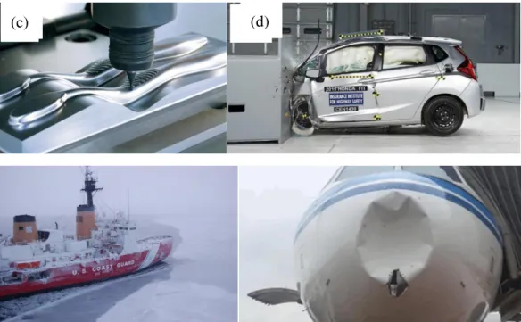
During the working and manufacturing process, materials may be subjected to impact loading over a wide range of strain rates and temperatures, Fig. 1.18. Therefore, a considerable amount of work has been done over the last decades to study the impact behavior of materials [29,30].
Fig. 1.18. Engineering applications where metallic alloys may be subjected to impact loading over various strain rates and temperatures. (a) high speed machining, (b) automotive industry, (c) naval industry and (d) aviation industry.
According to the impact velocity, investigation on the impact behavior of materials can be divided into 3 categories. The first category refers to low velocity impact (<50 m/s), where thin plates are commonly perforated by a drop weight tower [31]. The second covers sub-ordnance and ordnance velocity range between 50 and 1300 m/s, where projectiles are usually accelerated by a compressed air gas gun to perforate or penetrate plates [30]. The last category refers to hypervelocity impact (>1300 m/s), a velocity range often encountered in outer space impact such as debris hitting spacecraft [32].
37
The results are shown in Fig. 1.21. The ballistic limit velocity was affected by a combination of target thickness and projectile shape: the ballistic limit velocity increased from 38 m/s to 75 m/s, a doubled increase, when conical projectile was adopted; while the corresponding ballistic limit velocity changed only from 95 m/s to 130 m/s with a hemispherical projectile.
Fig. 1.20. Geometry and dimensions (mm) of the projectiles used in the experiments [39].
Fig. 1.21. The residual-initial velocity curves: (a) conical projectile configuration and (b) hemispherical projectile configuration [39].
Another parameter that has an influence on the ballistic impact behavior of thin plates is multiple-layered plates combination. Alavi Nia and Hoseini [85] compared ballistic resistance performance of monolithic, in-contact layered and spaced layered aluminium plates. They found that under the same total target thickness, the monolithic target behaves the best, followed by in-contact layered target and the spaced layered target behaves the worst. This is mainly because a bounding force between molecules inside the monolithic target exists, the energy needed to perforate
38
the plate is high. In case of in-contact layered target, deflection of the first layer is inhibited by the second and the third layers, so it behaves better than the spaced layered target.
Moreover, Børvik et al. [36,38] investigated the effects of projectile shape on perforation behavior of metallic materials. They conducted perforation tests of Weldox 460E steel plates using blunt, conical and hemispherical projectiles. The experimental results are shown in Fig. 1.22 and Fig. 1.23. It was found that both the energy absorption capacity and the failure mode of the material were affected by the projectile nose shape. The ballistic limit velocities are 185 m/s, 300 m/s and 300 m/s for blunt, conical and hemispherical projectiles, respectively. The failure mode for the blunt projectile was shear banding while conical and hemispherical projectiles perforated the target by pushing the material aside, corresponding to a failure by ductile hole enlargement.
Fig. 1.22. The residual-initial velocity curves for different projectile nose shapes [36,38].
39
Fig. 1.23. (a) Cross-section surface and (b) fracture pattern and the plugs after tests [36,38].
5.2 Perforation behavior of thin plates under various
temperatures
Concerning the perforation behavior of materials under various temperatures, quite a limited number of studies can be found. Mostly, the low temperature impact studies focus on hypervelocity impact of lightweight alloys and composites at around -173°C [40-43].
In addition, with a specially designed drop weight tower, the low velocity impact behavior of AA 2024-T3 aluminium and TRIP 1000 steel at -60°C was investigated by Martínez et al. [44,45]. The initial-residual velocity curves under different temperatures are shown in Fig. 1.24. It was found that the target absorbs larger impact energy with decreasing temperature, and the improved protection performance at low temperature comes from temperature sensitivity of materials. Under the same testing condition, he studied perforation behavior of TRIP 1000 steel and came to a similar conclusion. One should be noticed that no martensitic transformation was measured during perforation tests of TRIP steel, even at -60°C. Therefore, the improved protection performance of TRIP 1000 steel at low temperature comes from temperature sensitivity of the material instead of the originally assumed martensitic transformation.
40
Fig. 1.24. The initial-residual velocity curves at (a) 213 K and (b) 288 K for AA 2024-T3 and TRIP 1000 sheets [45].
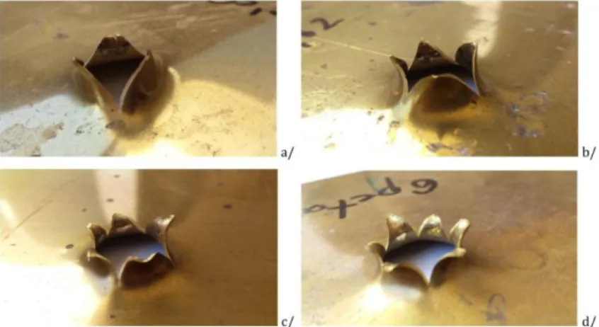
Concerning the impact behavior of materials under sub-ordnance or ordnance velocity at different temperatures, high temperature perforation by several authors were found [46-48]. Rusinek et al. [46] developed a heating chamber coupled to the ballistic impact device to investigate perforation behavior of Poly (Methyl methacrylate) (PMMA). With the thermal chamber, Klosak et al. [48] studied perforation behavior of brass alloy plates under temperatures ranging from 20°C to 260°C. The results are shown in Fig. 1.25 and Fig. 1.26. It can be seen that the energy absorption capacity decreased with increasing temperature. There were also some changes in the petalling failure mode: the number of petals increased from 3 to 6 within the testing temperature regime.
41
(a) 20°C, (b) 100°C, (c) 200°C and (d) 260°C [48].
Fig. 1.26. The initial-residual velocity curves for 20°C and 260°C [48].
Liu et al. [47] investigated the ballistic performance of GH4169 alloy at temperatures ranging from 25°C to 600°C. A similar conclusion was obtained: larger plastic deformation of specimens and lower ballistic limit velocities at higher temperatures.
Conclusion
In this chapter, the current researches of 304 ASS under strain rates and temperatures have been reviewed.
First, martensitic transformation is commonly observed in 304 ASS and it affects the deformation behavior obviously. Therefore, the effects of strain rate and temperature on martensitic transformation have been reviewed. After that, effects of temperature and strain rate on constitutive behavior of 304 ASS was studied. The deformation mechanism is explained by taking martensitic transformation and dislocation slip into consideration. In addition, several commonly used models describing the constitutive behavior of metallic alloys and martensitic transformation in 304 ASS were introduced.
42
Second, to study deformation and failure behavior of 304 ASS under extreme high strain rates, several representative shear specimens and the corresponding testing techniques were introduced. The advantages and disadvantages of each design were discussed.
Finally, the perforation behavior of metallic alloys under various conditions has been studied. The study mainly focused on influence of target thickness, multiple-layered plates combination, projectile shape and testing temperature on perforation behavior such as the failure patterns and the initial-residual velocity curves.
Depending on the facilities available in the LCFC (Laboratoire de Conception Fabrication Commande) and LEM3 (Laboratoire d‘Étude des Microstructures et de Mécanique des Matériaux) in Metz Campus of ENSAM (École Nationale Supérieure et d‘Arts et Métiers), the deformation behavior of 304 ASS under different strain rates and temperatures will be studied. First, compression tests of 304 ASS under a wide range of strain rates and temperatures will be performed and the constitutive behavior will be modeled by an extension of the R-K model considering martensitic transformation phenomenon. Second, a new shear specimen for extreme high strain rate study will be designed. It works together with the conventional SHPB system without any clamping system or screws. In addition, a cooling device for low temperature perforation tests will be designed. With the cooling system, the effect of temperature on the perforation behavior of 304 ASS will be investigated.
References
[1] Hickel T, Grabowski B, Körmann F, Neugebauer J. Advancing density functional theory to finite temperatures: methods and applications in steel design. J Phys: Condens Matter 2011;24:053202. doi:10.1088/0953-8984/24/5/053202. [2] Ishimaru E, Hamasaki H, Yoshida F. Deformation-induced martensitic transformation behavior of type 304 stainless steel sheet in draw-bending process.
43
Journal of Materials Processing Technology 2015;223:34–8. doi:10.1016/j.jmatprotec.2015.03.048.
[3] Byun TS, Hashimoto N, Farrell K. Temperature dependence of strain hardening and plastic instability behaviors in austenitic stainless steels. Acta Materialia 2004;52:3889–99. doi:10.1016/j.actamat.2004.05.003.
[4] Masumura T, Nakada N, Tsuchiyama T, Takaki S, Koyano T, Adachi K. The difference in thermal and mechanical stabilities of austenite between carbon- and nitrogen-added metastable austenitic stainless steels. Acta Materialia 2015;84:330– 8. doi:10.1016/j.actamat.2014.10.041.
[5] Beese AM, Mohr D. Effect of stress triaxiality and Lode angle on the kinetics of strain-induced austenite-to-martensite transformation. Acta Materialia 2011;59:2589–600. doi:10.1016/j.actamat.2010.12.040.
[6] Takaki S, Fukunaga K, Syarif J, Tsuchiyama T. Effect of Grain Refinement on Thermal Stability of Metastable Austenitic Steel. Mater Trans 2004;45:2245–51. doi:10.2320/matertrans.45.2245.
[7] Lichtenfeld JA, Van Tyne CJ, Mataya MC. Effect of strain rate on stress-strain behavior of alloy 309 and 304L austenitic stainless steel. Metall and Mat Trans A 2006;37:147–61. doi:10.1007/s11661-006-0160-5.
[8] Hamada AS, Karjalainen LP, Misra RDK, Talonen J. Contribution of deformation mechanisms to strength and ductility in two Cr–Mn grade austenitic stainless steels. Materials Science and Engineering: A 2013;559:336–44. doi:10.1016/j.msea.2012.08.108.
[9] Kim H, Lee J, Barlat F, Kim D, Lee M-G. Experiment and modeling to investigate the effect of stress state, strain and temperature on martensitic phase transformation in TRIP-assisted steel. Acta Materialia 2015;97:435–44.
![Fig. 1.3. Effect of temperature on the Gibbs free energy of both martensite and austenite phases [10,11]](https://thumb-eu.123doks.com/thumbv2/123doknet/2625933.58759/19.892.248.656.688.1030/fig-effect-temperature-gibbs-energy-martensite-austenite-phases.webp)
![Fig. 1.6. Temperature dependence of engineering stress-strain curves for 304 stainless steel [3]](https://thumb-eu.123doks.com/thumbv2/123doknet/2625933.58759/22.892.231.655.563.961/temperature-dependence-engineering-stress-strain-curves-stainless-steel.webp)
![Fig. 1.10. Comparison between experiments, the original R-K model and the extended R-K model at different strain rates: (a) 2591 s -1 ; (b) 5192 s -1 [22]](https://thumb-eu.123doks.com/thumbv2/123doknet/2625933.58759/34.892.144.747.303.551/comparison-experiments-original-extended-model-different-strain-rates.webp)
![Fig. 2.16. Evolution of the specific heat of 304 ASS with the testing temperature [8]](https://thumb-eu.123doks.com/thumbv2/123doknet/2625933.58759/94.892.276.616.267.537/fig-evolution-specific-heat-ass-testing-temperature.webp)