Titre:
Title:
A2×1LINC transceiver for enhanced power transmission in wireless
systems
Auteurs:
Authors
: Mohamed Abd Elaal et Fadhel Ghannouchi
Date: 2007
Type:
Article de revue / Journal articleRéférence:
Citation
:
Abd Elaal, M. & Ghannouchi, F. (2007). A2×1LINC transceiver for enhanced power transmission in wireless systems. Research Letters in
Communications, 2007, p. 1-4. doi:10.1155/2007/45301
Document en libre accès dans PolyPublie
Open Access document in PolyPublie URL de PolyPublie:
PolyPublie URL: https://publications.polymtl.ca/3658/
Version: Version officielle de l'éditeur / Published versionRévisé par les pairs / Refereed Conditions d’utilisation:
Terms of Use: CC BY
Document publié chez l’éditeur officiel
Document issued by the official publisherTitre de la revue:
Journal Title: Research Letters in Communications (vol. 2007) Maison d’édition:
Publisher: Hindawi URL officiel:
Official URL: https://doi.org/10.1155/2007/45301 Mention légale:
Legal notice:
Ce fichier a été téléchargé à partir de PolyPublie, le dépôt institutionnel de Polytechnique Montréal
This file has been downloaded from PolyPublie, the institutional repository of Polytechnique Montréal
Volume 2007, Article ID 45301,4pages doi:10.1155/2007/45301
Research Letter
A 2
×
1 LINC Transceiver for Enhanced Power Transmission in
Wireless Systems
Mohamed Abd Elaal1and Fadhel Ghannouchi2
1Poly-GRAMES, D´epartement de G´enie ´Electrique, ´Ecole Polytechnique de Montr´eal, Montr´eal, Canada H3T 1J4
2Iradio Laboratory, ECE Department, University of Calgary, 2500 University Dr. NW, Calgary, AB, Canada T2N1N4
Correspondence should be addressed to Mohamed Abd Elaal,[email protected]
Received 24 October 2007; Accepted 10 December 2007 Recommended by Peter Jung
A 2×1 LINC transceiver based on linear amplification using nonlinear components (LINC) architecture for wireless systems applications is proposed. The layout of the new architecture is presented and the simulation results show that the overall power efficiency of this architecture is superior by more than 300% when compared with that of a regular LINC amplifier. Also the adja-cent channel power ratio (ACPR) is lowered to−64.2 dBc, compared to−26.1 dBc for regular LINC, which improves the system
immunity against complex gain imbalances between LINC branches.
Copyright © 2007 M. Abd Elaal and F. Ghannouchi. This is an open access article distributed under the Creative Commons Attribution License, which permits unrestricted use, distribution, and reproduction in any medium, provided the original work is properly cited.
1. INTRODUCTION
The trend in the information technology field is pushing to-wards systems that offer higher transfer rates and free mo-bility. That implies moving towards wireless communication systems using digital modulation schemes to acquire maxi-mum benefit from the scarce and crowded spectrum. At the same time, these systems should be more efficient concern-ing power handlconcern-ing. The employment of complex modula-tion schemes to efficiently use the available tight bandwidth and incorporate higher data rates comes with complex mod-ulated signals containing high dynamics with increased peak-to-average power ratio (PAPR). This necessarily requires lin-ear amplification over a large power range, forcing the use of a low efficiency power amplifier working in a high back off which results in lower efficiency. Meanwhile in the lit-erature, one can find several approaches for improving the power amplifier (PA) efficiency while maintaining an accept-able linearity. One of which is the LINC power amplifier that is intended for use in wireless systems since it offers high ef-ficiency and linearity [1–4]. In the meantime, signal linearity is an important factor in determining how well a wireless sys-tem works, be it a cellular network, WLAN network, and so forth. Indeed, power amplifiers are the main source of non-linearities in these systems. Also emissions in the adjacent
channel are of a great concern as they reduce the number of active users who can be operating at the same time. The bit error rate (BER) also increases due to those emissions re-ducing the system quality of service (QoS). The nonlinear behavior of the system is determined by ACPR, which can be used to accurately show the linearity of a system. Also com-plex signals like OFDM impose strict requirements on trans-mitted signal linearity to meet the error vector magnitude (EVM) specification.
In this paper, a 2×1 amplification system is proposed. Simulated results of the power efficiency, EVM and ACPR performance, as well as the assessment of branches imbal-ance effects on the system performimbal-ance are presented. In Section 2, a brief description of the LINC concept is pre-sented;Section 3introduces the 2×1 LINC transceiver; while Section 4presents the results of efficiency, ACPR, and EVM performances.Section 5shows the imbalance behavior of the system. Finally, conclusions are presented inSection 6.
2. LINC AMPLIFIER
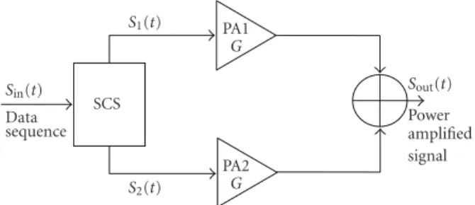
A regular LINC amplifier consists of a signal component sep-aration block (SCS), two identical power amplifiers, and a combiner. The SCS divides the baseband signal into two con-stant amplitude, phase-modulated signals. The two signals
2 Research Letters in Communications Sin(t) Data sequence SCS S1(t) S2(t) PA1 G PA2 G Sout(t) Power amplified signal
Figure 1: Regular LINC amplifier architecture.
are upconverted to RF, amplified, and summed by the power combiner to reconstruct an amplified replica of the input sig-nal, as shown inFigure 1. In this manner, the RF power am-plifiers are operated at saturation, and the two branch signals yield maximum amplifier efficiency and high linearity as the envelope of both signals is constant in magnitude [3–5].
3. THE 2×1 LINC TRANSCEIVER
In the proposed 2 ×1 LINC architecture, the amplified branch signals are transmitted, after being filtered to fit the standard mask for transmission, and amplified [5]. The re-ceiver antenna performs the signal combination as shown in Figure 2. The transmitter contains a DSP block and a Tx RF front end. The DSP block contains the SCS and shaping fil-ters. The SCS decomposes the baseband signal,Sin(t), into
two constant amplitude signals,S1(t) and S2(t), and
calcu-lates their rectangular representations (I1,Q1,I2,Q2), respec-tively. The digital shaping filters are used to fit the signal in each branch within the standard mask, and help lower out-of-band emissions, thus improving the ACPR of the resulting system. Filtering the branch signals of the LINC architecture introduces dynamics in the signal (the PAPR increases from 0.0 dB to approximately 3.6 dB), necessitating the use of lin-earization for the amplifiers, as they are working near satu-ration. Also the LINC transmitter contains the two antennas which are close enough such that it can be assumed that both transmitted signals will experience the same channel effect. This effect will be corrected for by the equalization algorithm performed at the receiver.
The receiver is of a regular WLAN architecture contain-ing an RF front end, which consists of Rx receiver, RF/IF con-version stage, A/D converter, and a digital DSP block. In this way, the power efficiency is improved as the combiner losses are eliminated. At the same time, the LINC branch imbal-ance effects can be tolerated up to some extent. The values of the EVM and PAPR for this 2×1 architecture assuming an ideal channel are 0.39% and 3.66 dB, respectively. These results show superior performance when compared to the LINC and single branch amplifier.
4. EVALUATION OF SYSTEM PERFORMANCE
The performance of the proposed 2×1 LINC system is evalu-ated through simulations; the advanced design system (ADS) software from Agilent Technologies was used. An indoor
Raleigh multipath fading channel was considered, as well as additive white Gaussian noise (AWGN) effects. An IEEE 802.11g OFDM signal with a 2.4 GHz frequency, 20 MHz bandwidth, 64 QAM modulation, 54 Mbps data rate, and sig-nal power of−10.0 dBm was used. Two class AB amplifiers
(HMC 408 from Hittite Inc.) were utilized to construct the LINC. The digital predistortion (DPD) technique was used to linearize the amplifiers to compensate for the PAPR in-crease due to filter effect. The LINC amplifiers characterizing data, (the AM-AM, AM-PM, and the synthesized AM-AM and AM-PM of the DPD) were measured and used in this study. The attenuation in the two LINC paths was assumed to be negligible. Meanwhile, the MATLAB software was used for filter synthesis. Digital FIR lowpass filters, with an order of 60, were used.
Simulations were carried out for the architectures single branch amplifier (Reg. Amp.), LINC (Reg. LINC), and 2×1 LINC. Results show that the branch signals to be transmit-ted after filtering fit within the transmission mask. Results also show that the efficiency of a regular LINC amplifier is 4.72%, while the EVM is 1.4% as shown inTable 1. When applying the filtering action in the 2×1 LINC system, and transmitting the branch signals, it is found that the new sys-tem efficiency is enhanced by about 3.4 times (from 4.72% to 16.17%), and the EVM remains almost constant. The branch signal of the 2×1 LINC system is complying with the stan-dard mask; meanwhile the ACPR performance of the system is improved. A comparison between the 2×1 LINC trans-mitted signal spectrum and that of the regular LINC in adja-cent channels is shown inFigure 3. It can be noted from the figure that the ACPR had improved significantly, especially when the least square filter was used. The use of the least square filter results in a sharp stable spectrum; and the ACPR was improved by 43 dB and by 37 dB when compared to the standard specification and the LINC amplifier, respectively. In addition, the system efficiency is enhanced due to the re-moval of the combiner. This result implies that the system can tolerate higher channel interference levels and also can self-compensate for LINC imbalances. The ACPR improve-ment for this new transmitter is also illustrated inFigure 4 [5] for different input power levels compared to those of an LINC and single branch amplifier.
5. IMBALANCE EFFECTS
The parallel RF branches of the LINC transmitter suffer from unavoidable difference in their magnitudes and phase re-sponses. Imbalance effects between the two LINC branches are studied. This effect was corrected using different tech-niques that are complex implementations [6]. Meanwhile in the proposed 2×1 LINC, and due to using the branch digi-tal filtering, a solution without any overhead on the system is achieved. The filters improve the ACPR performance of the system and help it to tolerate the imbalance effect.
Table 2 shows the imbalance values between the two branch signals’ magnitudes and phases, the entries in the ta-ble show the EVM values. The ACPR did not change signif-icantly: it was lowered by only 1.3 dB in the case when a 3-degree phase and 0.1 magnitude imbalance was considered.
Sin(t) SCS DSP I1 Q1 I2 Q2 Shaping filter bank + I/Q mod DAC DAC S1(t) S2(t) Up converter TX/RF PA PA ST1(t) ST2(t) SR(t) LNA Down converter RX/RF ADC Equalizer DSP Sout(t)
Figure 2: Detailed layout of the proposed 2×1 LINC architecture. Table 1: ACPR, efficiency, and EVM without and with filtering.
Filter type ACPR@11 MHz ACPR@20 MHz ACPR@28 MHz Efficiency EVM Specs −20 dBc −28 dBc −40 dBc — 5.62% Reg. LINC −26.1 dBc −51.1 dBc −56.9 dBc 4.72% 1.40% 2×1 LINC −63.1 dBc −70.2 dBc −70.2 dBc 16.17% 1.53%
Table 2: EVM values for different phase and magnitude imbalances. Phase/Mag. 0.1 0.2 0.3 0.4 0.5 10 2.05% 2.78% 3.48% 4.28% 5.13% 20 3.37% 3.88% 4.44% 5.12% 5.88% 30 5.04% 5.32% 5.77% 6.34% 7.00% 2440 2430 2420 2410 2400 2390 2380 2370 2360 Frequency (MHz) −80 −70 −60 −50 −40 −30 −20 −10 0 PSD (dBm) Strans-regular LINC Strans 2×1 LINC Mask 2×1 LINC Regular LINC
Figure 3: Comparison of the spectrum of transmitted signals of 2×1 LINC systemST2(t) and the regular LINC system Sout(t) shown
inFigure 1, with respect to the mask of the 802.11g standard.
In addition, the efficiency was lowered to 4.22%. Of course, cases where the EVM exceeded 5.6% are not accepted as they were over the standard limit.
6. CONCLUSION
A 2×1 LINC transceiver architecture suitable for wireless transceivers is proposed. It is based on DSP implementation where the LINC input signal separation and branch signal fil-tering are carried out. The signal combining is carried out at
−10 −15 −20 −25 −30 −35 Pin(dBm) −90 −80 −70 −60 −50 −40 −30 −20 −10 0 A C PR at 11 MHz off set (dBc) Specs RegAmp11 RegLINC11 ModLINC11 −20 dBc linearity spec. at 11 MHz Reg Ampl Reg LINC 2×1 LINC
Figure 4: ACPR at 11 MHz offset for the 2×1 LINC, regular LINC, and regular amplifier for different input power levels.
the antenna of the receiver side. This new layout is designed to overcome the problems associated with the transmitter combiner losses. The results show improved backoff opera-tion for the branch amplifier from 9.4 dB for a single branch amplifier to 3.66 dB. It is close to that of regular LINC, which implies an overall power efficiency improvement from 1.43% for a single branch amplifier, and 4.72% for LINC, to 16.17% for the proposed 2×1 LINC. The EVM is 1.53% which is low compared with the standard allowed value of 5.6%. In this system, the signals in the two LINC branches are filtered to fit the transmission mask and lower their ACPR. The ACPR performance is greatly improved, which enables the tolera-tion of higher channel interference levels and LINC branch imbalances; meanwhile the system’s overall efficiency is im-proved as the combiner in the transmitter is removed.
Results show that the ACPR is improved by 43 dB when using the least square filter. In the meantime, the system effi-ciency is enhanced by 3.4 times when compared to that of an LINC amplifier. The filter action does not affect the system
4 Research Letters in Communications performance in regard to the EVM, as the results show. This
new 2×1 system has the advantage of having standard re-ceiver architecture while delivering an improved system per-formance regarding efficiency, ACPR, and EVM.
ACKNOWLEDGMENTS
This work was financially supported by the Natural Sciences and Engineering Research Council of Canada (NSERC), Canada Research Chairs (CRC), and the Informatics Circle of Research Excellence (iCORE), and The Higher Education Ministry of EGYPT. The authors would like to thank Mr. Mohamed Helaoui for his help and support to complete this work.
REFERENCES
[1] F. H. Raab, “Efficiency of outphasing RF power-amplifier sys-tems,” IEEE Transactions on Communications, vol. 33, no. 10, pp. 1094–1099, 1985.
[2] R. Dinis and A. Gusmao, “Performance evaluation of OFDM transmission with conventional and two-branch combining power amplification schemes,” in Proceedings of Global
Telecom-munications Conference (GLOBECOM ’96), vol. 1, pp. 734–739,
London, UK, November 1996.
[3] D. C. Cox, “Linear amplification with nonlinear components,”
IEEE Transactions on Communications, vol. 22, no. 12, pp. 1942–
1945, 1974.
[4] A. Birafane and A. Kouki, “An analytical approach to LINC power combining efficiency estimation and optimization,” in Proceedings of the 33rd European Microwave Conference
(EuMC ’03), vol. 3, pp. 1227–1229, Munich, Germany, October
2003.
[5] M. Abd Elaal and F. Ghannouchi, “ACPR performance study for modified LINC amplifier,” in Proceedings of the 13th IEEE
International Conference on Electronics, Circuits and Systems (ICECS ’06), pp. 435–438, Nice, France, December 2006.
[6] M. Helaoui, S. Boumaiza, A. Ghazel, and F. Ghannouchi, “Dig-ital compensation of branches imbalance effects in LINC trans-mitters,” in Proceedings of the 16th International Conference on
Microelectronics (ICM ’04), pp. 688–691, Tunis, Tunisia,
Internatfional Journal of
A
e
ro
spa
c
e
Eng
fin
e
e
r
fing
Hfindawfi Publfishfing Corporatfionhttp://www.hfindawfi.com Volume 2010
Robo
Journal ot
fics
fH findawfi Publfishfing Corporatfion
http://www.hfindawfi.com Volume 2014
H findawfi Publfishfing Corporatfion
http://www.hfindawfi.com Volume 2014
Actfive and Passfive Electronfic Components
Control Scfience and Engfineerfing Journal of
H findawfi Publfishfing Corporatfion
http://www.hfindawfi.com Volume 2014
Machfinery
H findawfi Publfishfing Corporatfion
http://www.hfindawfi.com Volume 2014 H
findawfi Publfishfing Corporatfion http://www.hfindawfi.com
Journal of
En
g
fin
e
er
fin
g
Volume 2014
Subm
fi
t
your
manuscr
fip
ts
a
t
h
t
tp
:
/
/www
.h
findaw
fi
.com
VLSI Desfign
Hfindawfi Publfishfing Corporatfion
http://www.hfindawfi.com Volume 2014
H findawfi Publfishfing Corporatfion
http://www.hfindawfi.com Volume 2014
Shock and Vfibratfion
H findawfi Publfishfing Corporatfion
http://www.hfindawfi.com Volume 2014
C
Advancesfiv
fi
l
Eng
finfinee
r
fing
AcousAdvancestficsfin and Vfibratfion
H findawfi Publfishfing Corporatfion
http://www.hfindawfi.com Volume 2014 H
findawfi Publfishfing Corporatfion
http://www.hfindawfi.com Volume 2014
Electrfical and Computer Engfineerfing
Journal of
Advancesfin OptoElectronfics
Hfindawfi Publfishfing Corporatfion
http://www.hfindawfi.com Volume 2014
The
Sc
fient
fific
Wor
ld
Journa
l
H findawfi Publfishfing Corporatfion
http://www.hfindawfi.com Volume 2014
Senso
JouHfindawfi Publrnafishfing Corporatl ofionfrs
http://www.hfindawfi.com Volume 2014
Modellfing & Sfimulatfion fin Engfineerfing
Hfindawfi Publfishfing Corporatfion
http://www.hfindawfi.com Volume 2014
H findawfi Publfishfing Corporatfion
http://www.hfindawfi.com Volume 2014
Chemfical Engfineerfing
InternatfionalJournal of Antennas and
Propagatfion
InternatfionalJournal of
H findawfi Publfishfing Corporatfion
http://www.hfindawfi.com Volume 2014 H findawfi Publfishfing Corporatfion
http://www.hfindawfi.com Volume 2014
Navfigatfion and Observatfion
InternatfionalJournal of
H findawfi Publfishfing Corporatfion
http://www.hfindawfi.com Volume 2014