Development of high-power 3 µm
fiber laser sources and components
Thèse
Yi ˘git Ozan Aydın
Doctorat en physique
Philosophiæ doctor (Ph. D.)
Québec, Canada
Development of high-power 3 µm
fiber laser sources and components
Thèse
Yi ˘git Ozan Aydın
Sous la direction de:
Martin Bernier, directeur de recherche Réal Vallée, codirecteur de recherche
Résumé
Les systèmes laser en fibre optique de verre fluoré se sont placés en tête de file pour la génération de lumière cohérente dans l’infrarouge moyen, de 2 à 5 µm. En particulier, les lasers à fibre opérant à 3 µm ont attiré une attention considérable puisqu’ils permettent le développement d’applications en spectroscopie, en contre-mesure militaire et en médecine. De ce fait, ces lasers ont connu des progrès considérables en termes de puissance, de qualité de faisceau, de fiabilité et de compacité dans la dernière décennie.
Cette thèse s’inscrit dans cette démarche d’accroissement des performances des lasers à fibre infrarouges opérant à 3 µm. Ainsi, elle présente différents systèmes laser en fibre de verre fluoré et détaille les composants tout-fibre qui ont permis d’atteindre des records d’efficacité énergétique, de puissance et d’énergie par impulsion.
Trois types de sources laser, chacune ayant établi un record de performance, ont été inves-tiguées. Tout d’abord, une efficacité laser record de 50% a été obtenue à partir d’un laser à fibre opérant à 2.8 µm en utilisant le principe de cascade laser à 2.8 et 1.6 µm. Ensuite, un amplificateur à fibre, basé sur des fibres dopées à l’ion erbium et aux ions holmium et praséodyme, a permis d’amplifier des impulsions picosecondes à 3 µm d’une source laser à l’état solide pour obtenir une énergie par impulsion (122 µJ) et une puissance moyenne (2.45 W) records. Finalement, une cavité laser tout-fibre dopée à l’ion erbium opérant autour de 3 µm, dépourvue d’épissures fusionnées, a mené à la démonstration d’une puissance laser record de 41.6 W. D’autre part, cette thèse a ciblé différents obstacles limitant l’accroissement de la puissance des lasers à fibre opérant à 3 µm, et a permis d’identifier des pistes de solutions pour pallier ces limitations. En l’occurrence, la photodégradation de l’extrémité de sortie des lasers à fibre à 3 µm, causée par la diffusion de la vapeur d’eau ambiante, limite la durée de vie et la puissance maximale de ce type de laser. Ainsi, le dernier volet de cette thèse a été consacré à l’étude expérimentale de la photodégradation d’embouts de protection à base de verre fluoré ou d’oxyde. Cette étude a mené au développement d’une nouvelle méthode per-mettant d’inhiber la diffusion de la vapeur d’eau dans les embouts de protection. Cette thèse représente une avancée majeure dans le contexte de l’accroissement de la puissance des sources laser en fibre optique opérant à 3 µm et démontre leur potentiel indéniable pour remplacer d’autres types de lasers dans une multitude d’applications.
Abstract
Fluoride fiber laser technology is one of the noteworthy tools for generating coherent mid-infrared signal between 2 to 5 µm that has made outstanding progress over the last decade in terms of compactness, reliability, high beam quality, and output power. In the mid-infrared spectral region, laser emission near 3 µm is crucial for many applications such as spectroscopy, countermeasures and medicine. In addition, there has always been an increasing demand for higher laser output parameters to open new doors for potential applications.
This dissertation presents a series of experimental studies of fluoride fiber laser systems, either in continuous wave or pulsed regime, and of their critical in-fiber components to achieve a laser emission with high slope efficiency, output power, and pulse energy near 3 µm.
During this PhD project, three main 3 µm-class fluoride fiber laser sources, each representing at least one record output parameter in their own category, have been investigated. First, the highest optical-to-optical efficiency (50%) at 2.8 µm was achieved from a diode-pumped fiber laser cavity by cascaded transitions of 2.8 µm and 1.6 µm in a low-doped erbium fluoride fiber. Then, active media based on erbium and holmium/praseodymium zirconium fluoride fibers seeded by a sub-ns solid-state laser enabled to achieve highest pulse energy (122 µJ) and average power (2.45 W) from a picosecond fiber laser amplifier operating near 3 µm. Lastly, the highest average power 3 µm-class laser (41.6 W) has been demonstrated by using a splice-less heavily erbium-doped fluoride fiber medium. The major problems during the high-power laser operation have been investigated and potential solutions were proposed. The most common problem of all the high-power 3 µm fiber laser demonstrations is the degradation of the fiber tips due to OH migration, which limits the output power and can lead to catastrophic failures. Therefore, in the last part of the PhD project, the performance of fluoride- and oxide-based endcap components under high-power 3 µm laser emission has been experimentally investigated and a novel endcapping method was proposed for suppressing the OH migration. Experimental studies in this PhD project represents a significant advance for further power scaling of 3 µm fluoride fiber laser sources and shows their potential to replace other laser technologies.
Contents
Résumé iii
Abstract iv
Contents v
List of Tables vii
List of Figures viii
List of Abbreviations x
Acknowledgements xiii
Foreword xv
Introduction 1
I.1 Context and relevance . . . 1
I.2 Applications of 3 µm laser sources . . . 4
I.3 Fluoride fiber laser components . . . 8
I.4 Laser transitions of rare-earth ion dopants . . . 20
I.5 Current status of high-power 3 µm fiber laser systems . . . 39
I.6 Major challenges and proposed solutions . . . 44
I.7 Presentation of articles . . . 51
1 Diode-pumped mid-infrared fiber laser with 50% slope efficiency 54 1.1 Résumé . . . 54
1.2 Abstract . . . 55
1.3 Introduction. . . 55
1.4 Preliminary experiment . . . 57
1.5 Designing an optimized cavity . . . 60
1.6 Results and discussion . . . 61
1.7 Conclusion . . . 64
1.8 Supplementary material . . . 64
2 High-energy picosecond pulses from a 2850 nm fiber amplifier 68 2.1 Résumé . . . 68
2.2 Abstract . . . 68
2.4 Experiment . . . 70
2.5 Results and discussion . . . 73
2.6 Conclusion . . . 76
3 Towards power scaling of 2.8 µm fiber lasers 77 3.1 Résumé . . . 77
3.2 Abstract . . . 77
3.3 Introduction. . . 78
3.4 Experiment . . . 79
3.5 Results and discussion . . . 82
3.6 Fiber tip degradation. . . 84
3.7 Conclusion . . . 85
4 Endcapping of high-power 3 µm fiber lasers 86 4.1 Résumé . . . 86
4.2 Abstract . . . 87
4.3 Introduction. . . 87
4.4 Experimental setup . . . 88
4.5 Endcap splicing and manufacturing . . . 89
4.6 Results and discussion . . . 92
4.7 Conclusion . . . 97
Conclusion and perspectives 98
List of Tables
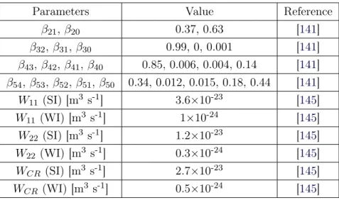
I.1 Branching ratios and energy transfer parameters for Er3+ system. . . . . 32
I.2 Branching ratios and energy transfer parameters for Ho3+ system. . . . . 37
I.3 Watt-level CW fluoride fiber lasers operating near 3 µm. . . 41
I.4 Watt-level pulsed fluoride fiber laser sources operating near 3 µm.. . . 44
2.1 Specification of doped fibers. . . 72
4.1 Endcap specifications. . . 90
List of Figures
I.1 Output power from fluoride fiber lasers based on Er3+, Ho3+ and Dy3+ gain
media operating near 3 µm in CW mode as a function of time . . . 3
I.2 Absorption spectrum of liquid water . . . 5
I.3 Absorption spectra of important trace gases in the spectral region between 2.5
and 5 µm . . . 7
I.4 Attenuation of ZrF4 and low-OH silica fiber . . . 9
I.5 Example of splices between (a) single-mode ZrF4 fibers with same clad sizes,
(b,c) ZrF4fibers with different core and clad sizes, and (d) splices between SiO2
and ZrF4 fibers by dielectric coating . . . 17
I.6 Emission cross-sections of rare earth ions for 3 µm laser emission in Er3+:ZrF 4
fibers. . . 21
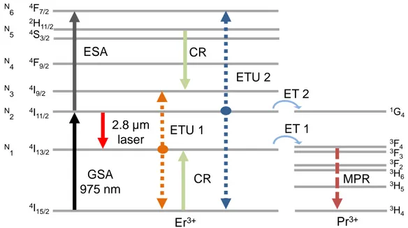
I.7 Simplified energy level diagram of heavily-doped Er3+:ZrF
4 fiber . . . 23
I.8 Estimated rate parameters for ETU1, ETU2and cross relaxations as a function
of Er3+ concentration in Er3+:ZrF
4 fibers . . . 24
I.9 Cross-section spectra of GSA and ESA in Er3+ fluoride glass . . . . 25
I.10 Simplified energy level diagram of Er3+:ZrF
4 for cascade transition at 1.6 and
2.8 µm. . . 28
I.11 Simplified energy level diagram of Er3+,Pr3+ co-doped ZrF
4 fiber . . . 31
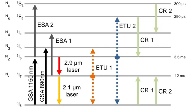
I.12 Simplified energy level diagram of Ho3+-doped ZrF
4 fiber . . . 33
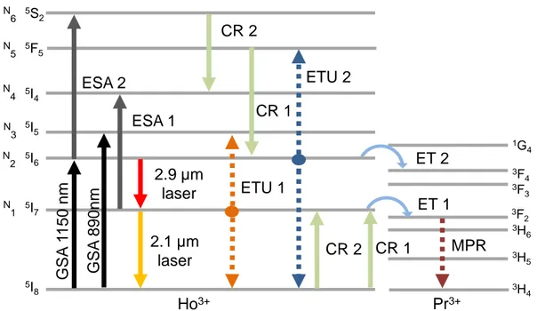
I.13 Simplified energy level diagram of Ho3+, Pr3+-doped ZrF
4 fiber . . . 35
I.14 Simplified energy level diagram of Dy3+-doped ZrF
4 fiber . . . 38
I.15 Absorption of three different low refractive index fluoroacrylate polymers. . . . 47
I.16 Demonstration of (a) the scattering of laser from splice point and (b) Fresnel
reflection at the air-glass interfaces . . . 48
I.17 (a) Schematic representation of the fiber degradation phenomenon and (b)
mi-croscope image of degraded fiber tip . . . 49
I.18 Laser induced fiber tip damage images of (a) a fiber facet without endcap, (b)
a fiber facet through the endcap and (c) an endcap splice interface. . . 50
1.1 Partial energy level diagram of the relevant energy states of the erbium ions in
fluoride glasses. . . 56
1.2 Experimental setup of the cascade laser operating at ∼2.8 and ∼1.6 µm that was used to test the performance against different gain fiber lengths (3, 7, and
10 m). . . 57
1.3 Measured output power with respect to the launched and absorbed pump powers
for cavity lengths of (a), (b) 3 m, (c), (d) 7 m, and (e), (f) 10 m. . . 59
1.4 Experimental setup of the optimized cascade laser operating at 2.825 and 1.614
1.5 Measured output powers at 1.6 and 2.8 µm with respect to absorbed pump
power for the 21 m fiber length. . . 62
1.6 Absorption spectrum of a 90 cm length of the 1 mol.% Er3+-doped fluoride fiber
between 1.55 and 1.80 µm for varying launched pump powers from 0 to 3.2 W. 63
1.7 Experimental setup used for the measurement of the excited state absorption
spectrum. . . 65
1.8 Absorption spectrum of a 90 cm length of the the 1 mol.% Er3+-doped fluoride
fiber between 1.5 and 2.1 µm when the 976 nm pump is turned off and on at a
launched pump power of 3.2 W.. . . 66
1.9 Transmission spectrum of both FBGs and output emission spectrum from the
cascade fiber laser. . . 67
2.1 (a) Experimental setup of the laser amplifier, (b) partial energy-level diagram
for Ho3+, Pr3+ doped fluoride fiber and (c) image of the S1 splice . . . . 71
2.2 (a) Measured output power with respect to launched pump after (a) first (b)
second and (c) third amplification stages. . . 73
2.3 Spectrum of the seed source and evolution of the spectrum after each
amplifi-cation stage. . . 74
2.4 (a) Measured output pulse train and (b) pulse profiles of the seed and amplified
pulses (Pout = 2.45 W). . . 74
2.5 Beam quality (M2) measurement for X and Y axes, inset; the image of the beam
recorded with a InSb camera. . . 75
2.6 Evolution of the output power near 1.5 W over 1-hour time period. . . 75
3.1 Experimental setup of the 42 W fluoride fiber laser at 2.824 µm. S, fusion splice
between SiO2 and Er3+:ZrF4 fibers . . . 79
3.2 Maximum temperature increase of the Er3+:ZrF
4 polymer jacket along with
pump central wavelength with respect to launched pump power.. . . 81
3.3 Transmission spectra of both HR- and LR-FBG after inscription and after
ther-mal annealing at 150°C for 10 minutes. . . 81
3.4 Measured output power at 2824 nm as a function of the total (forward and
backward) launched pump power around 980 nm. . . 83
3.5 Output laser spectra measured at 10.8, 19.5, 29 and 41.6 W. . . 83
3.6 (a) Temperature evolution of the AlF3and ZrF4endcaps at 20 W average output
power at 2.8 µm, the optical microscope image of AlF3 tip and (b) evolution
of the output power and central output wavelength near 20 W over a 6 h time
period.. . . 84
4.1 Experimental setup used to monitor the degradation over time of the different
endcaps when subjected to 20 W of output power at 3 µm.. . . 89
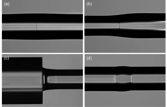
4.2 Photographs of the different endcaps taken with the imaging system of the
Vytran GPX. . . 91
4.3 Photographs of the interface between the ZrF4 relay fiber and (a) the SiO2 and
(b) the Er3+:YAG endcaps. . . . . 92
4.4 Measured temperature of the endcaps’ output face as a function time for a
constant 3 µm output power of 20 W. . . 93
4.5 Measured temperature of the (a) ZrF4, (b) AlF3 and (c) Al2O3 endcaps
List of Abbreviations
CPS cladding pump stripper CR cross relaxation
CW continuous wave
DFBL distributed feedback lasers
DFG difference-frequency generation systems DM dichroic mirror
ESA excited state absorption ET energy transfer
ETU energy transfer upconversion FBG fiber Bragg gratings
GSA ground state absorption
HR-DM highly reflective dichroic mirror HR-FBG high reflective fiber Bragg grating ICLs inter-band cascade diode lasers InGaAs indium gallium arsenide IR infrared
LID laser induced damage
LR-FBG low reflective fiber Bragg grating mid-IR mid-infrared
MOPA master oscillator power amplifier MPC multi pump combiner
MPR multiphonon relaxation NA numerical aperture
OPG optical parametric generation OPO optical parametric oscillators PbP point-by-point
PM polarization maintaining QCL quantum cascade lasers RMS root-mean square SC supercontinuum UV ultraviolet
VBG volume Bragg grating YAG yttrium aluminum garnet
Acknowledgements
This dissertation would not have been possible without many people who contributed to it in their own particular way and for that I want to thank them. First and foremost, I would like to thank my supervisor Martin Bernier for believing in me, for giving me a wonderful opportunity to be his PhD student and for being an excellent advisor. His magical word "easy!" has always been a moral support and has made every part of this journey easier. His outstanding guidance, advice, and support during this work encouraged me and allowed me to achieve significant scientific results. I am eternally indebted in my co-supervisor Réal Vallée who enlightened and motivated me with his immense knowledge, enthusiasm, and wise advice. He provided a dynamic and excellent research environment with the most modern equipment and generous research support. Finally, I would like to thank my both supervisors for the financial support I received through their projects and for allowing me to participate in international conferences, trainings, and high-level meetings.
Vincent Fortin deserves a very special word of gratitude. I always feel lucky to have had a chance to work with him and learn from him. He has always taken the time to discuss and enrich my work, helped me with all my experimental work, and I would not be where I am today without him.
I would like to thank Frédéric Maes, a great friend and office mate, who generously gave his time to offer me valuable comments toward improving my dissertation and made excellent scientific contributions to my research work.
Many members of Bernier and Vallée research groups contributed to my research project and helped me along the way. I would like to thank especially Pascal Paradis and Frédéric Jobin for insightful discussions and their help concerning the numerical simulations and my common computer related problems. Thanks to Simon Duval, Jean-Christophe Gauthier, Louis-Rafaël Robichaud, Souleymane T. Bah and Louis-Philippe Pleau for their friendship and support in the laboratory. I feel always lucky to have them as friends.
I would like to thank Stuart D. Jackson and Darren Kreamer for their excellent scientific contributions to my research work.
project, especially Marc d’Auteuil and Stéphan Gagnon who were always available and an-swered with a great patience to all my technical needs.
I am grateful to all of the Centre d’optique photonique et laser (COPL) members I had the pleasure to work with during my PhD project, especially, Diane Déziel who has always supported and helped me for completing my out-of-lab tasks with her invaluable service. I am deeply grateful to Michel Piché for agreeing to read my thesis before the initial deposit. I thank my committee members Younes Messaddeq, F.Ömer İlday and Michel Piché for their guidance and for accepting to serve on my committee.
The list of people who contributed to my happiness outside the professional context is quite exhaustive, but I would like to thank especially Tolga Tezcan, Andréanne Béland, Sasan Zhalehpour, Alexandre Arsenault-Bourdeauand, Çağatay Göde, Koray Eken, Emre Yağcı and Caner Boyraz for their love, care and moral support. I feel so lucky and am so thankful to have such wonderful people in my life.
A very special thanks to my family for their endless love and support. The words cannot express how grateful I am to my mother, father and brother who encouraged me all the time and this work would not have been possible without them. In addition, thanks to my aunt and uncle who have always supported me with their love.
Prof. Vallée asked me if I was sure I wanted to live at -40 ℃ as a first question of my PhD interview before I moved to Canada. At that time it was impossible to imagine the benefits of winter but it now deserves an appreciation. A final thank to Québec’s winter for motivating me to complete my PhD as soon as possible.
Foreword
This thesis deals with the development of high-power 3 µm fluoride-based fiber laser sources and of their in-fiber components. High power fiber laser development near 3 µm is a consider-ably challenging process due to the weak mechanical and thermal properties of fluoride fibers and the limitations related to the development of laser components based on fluoride glass. In this thesis, three fluoride fiber laser systems based on different active media have been de-signed and experimentally demonstrated. The limiting factors for achieving high-power laser operation in fluoride fibers have been studied which resulted in a record laser slope efficiency, a record laser output power, and a record laser pulse energy near 3 µm from each system, respectively. Moreover, the degradation of fiber tip due to OH migration that is the major limiting factor for 3 µm laser power scaling was experimentally studied by investigating the performance of different endcap components under high-power laser emission. A novel method has been proposed to overcome this problem which consists of sputtering a barrier film on the endcap face. This work has been carried out under the supervision of Martin Bernier (di-rector) and Réal Vallée (co-di(di-rector) in the Centre for Optics, Photonics and Lasers at Laval University.
Organization of Thesis
This thesis is organized with an introduction, 4 chapters and a conclusion. The introduction part consists of the idea behind the thesis and an overview of the applications that can benefit from 3 µm laser emission. Then, the importance of main fluoride fiber laser components followed with points to take into consideration during their fabrication is given. It also presents a theoretical overview of 3 µm transition from rare-earth doped fluoride fibers with a literature review and a content outlining the current status of these lasers. The major challenges while developing high-power fluoride fiber lasers are highlighted along with their proposed solutions in the last part of the introduction. The concepts exposed in this part are essential for a good understanding of the following chapters. Each of the chapters from 1 to 4 corresponds to an article which was published as part of the PhD project and one supplementary material belongs to the article presented in chapter 1. In the last part, the conclusion of the thesis and discussion of possible short- and long-term research projects are given.
Personal contribution to the presented articles
The layout of the figures was modified to adapt articles to the single column template of the thesis and the contents of the articles were divided into sections. All references in the articles are incorporated into the bibliography at the end of the thesis. The citation numbers in square brackets corresponding to each of the references may therefore differ from the original article. Apart from these modifications, no changes have been made to the published articles.
Chapter 1 presents an article "Diode-pumped mid-infrared fiber laser with 50% slope effi-ciency," published in Optica, Vol. 4, pp 235-238 (Y.O. Aydin, V.Fortin, F. Maes, F. Jobin, S.D. Jackson, R. Vallée, and M. Bernier). The laser demonstrated in this work has an out-put power of 12.95 W at 2.8 µm with a slope efficiency of 49.5%. This slope efficiency is the highest optical-to-optical conversion efficiency achieved from a diode-pumped mid-infrared fluoride fiber laser thanks to a new excited state absorption discovered in erbium-doped zirco-nium fluoride fiber. My contribution to this work can be divided into four points: Assembling the laser cavity, conducting all the experimental measurements, writing the manuscript and supplementary material as a first author, compiling all the figures presented in the article and supplementary material. Fiber Bragg gratings (FBG) in this work were fabricated by Martin Bernier. I also presented the result of this study at CLEO Europe (The European Conference on Lasers and Electro-Optics) in Munich, Germany in 2017.
The article in Chapter 2, "High-energy picosecond pulses from a 2850 nm fiber amplifier" is a demonstration of a three-stage fluoride fiber amplifier seeded by an optical parametric oscillator and it was published in Optics Letters, Vol. 43, pp. 2748-2741 (Y.O. Aydin, V. Fortin, D. Kraemer, A. Fraser, R. Vallée, and M. Bernier). In this work, the obtained pulse energy (122 µJ) was the highest ever produced from a fluoride fiber amplifier and the average power (2.45 W) is a record for a sub-ns 3 µm class fiber laser source. My contribution to this work is similar to the article presented in Chapter 1. Another version of the amplifier delivering 100 µJ pulses by using different seed source and one amplification medium was demonstrated and presented at the 8th EPS-QEOD Europhoton Conference in Barcelona, Spain in 2018. "Towards power scaling of 2.8 µm fiber lasers" is a high-power continuous-wave demonstration of a 3 µm-class fiber laser presented in Chapter 3. It was published in Optics Letters, Vol. 43, pp. 4542–4545 (Y.O. Aydin, V. Fortin, R. Vallée, and M. Bernier). In this work, a record output power (41.6 W) from a fiber laser operating near 3 µm was reported and the long-term performance of two commonly used endcap components was investigated. The laser cavity in this work is the first splice-less demonstration of high-power 3 µm-class fluoride fiber laser and represents a significant advance for further power scaling of such lasers. My contribution to this work is similar to the article presented in Chapter 1. FBGs in this work were fabricated by Martin Bernier. I presented the preliminary results of this work at 20th Photonics North Conference in Montreal, Canada in 2018. Then, I presented the results at
CLEO US (Conference on Lasers and Electro-Optics) in San Jose, the United States in 2018. In Chapter 4, another article entitled "Endcapping of high-power 3 µm fiber lasers" is pre-sented. This article was published in Optics Express, Vol. 27, pp. 20659–20669 (Y.O. Aydin, F. Maes, V. Fortin, S.T. Bah, R. Vallée and M. Bernier). The article given in Chapter 3 high-lights the photo-degradation of fiber tips as the main limitation of power scaling and long-term performance of high-power 3 µm-class fiber lasers. Therefore, to investigate solutions for this problem, the research work presented in Chapter 4 focuses on OH-diffusion related degrada-tion of various endcaps by comparing their performances under high-power laser radiadegrada-tion at 3 µm. In this study, sputtering a nanoscopic diffusion barrier film on the output face of the endcap component was proposed as a new method to completely suppress OH diffusion from output fiber face. It is believed that thanks to this novel method, the long-term oper-ation of 100-W-level 3 µm fiber lasers will be feasible. My contribution to this work can be divided into five points : Assembling a stable 25 W laser cavity used in the long-term tests, conducting all the experimental measurements of laser cavity, fabricating all the fluoride- and fluorogermanate-based endcaps, conducting long-term endcap performance experiments ex-cept one with nanoscopic thin-film of silicon nitride and writing the manuscript as a shared first authorship together with Frédéric Maes.
Introduction
This part consists of 7 sections. The first section (I.1) is providing the context and relevance of the work by briefly introducing the main idea behind this thesis and the importance of the research work. Section I.2 gives an overview of the applications that can benefit from 3 µm laser sources. In section I.3, the importance of the main components of the fluoride fiber laser is discussed and points to take into consideration during their fabrication are described. The theoretical overview of 3 µm transitions from rare-earth doped fluoride fibers is given in section I.4. A literature review with the current state of high-power 3 µm fiber lasers and current challenges are described in sections I.5 and I.6, respectively. In the last section (I.7), presentation of the articles published in the context of the PhD project is given.
I.1
Context and relevance
It has been more than century since Albert Einstein proposed the stimulated emission theory which is the fundamental idea behind laser science. After the invention of the first laser [1], which was based on laser emission from a ruby crystal, laser technology has made tremendous progress and nowadays lasers are found almost everywhere in daily life. As lasers evolve and become an integral part of modern society, so do the many other applications in the area of manufacturing, construction, telecommunication, automotive, medicine, security, etc. There are various types of lasers which are divided into different types according to their active media. Fiber lasers, in which the laser beam propagates through the glass-based core of an optical fiber, have become one of the most popular laser technologies thanks to their potential for power and brightness scalability, excellent beam quality, high efficiency, and reliability. After the first experimental demonstration of laser operation in a fiber [2], it has taken more than 20 years to develop a technique for fabricating low-loss rare earth doped single and multimode optical fibers [3] which is one of the most important milestones in fiber laser technology. In the first place, fiber lasers started to be used in telecommunication area, then the invention of double clad silica fibers enabled the achievement of high output powers, and their eventual use in other areas. As laser technology revolutionized many sectors, research has continuously grown to improve laser components as well as output beam parameters such as average power, peak power, pulse energy, and beam profile. There is always an increasing demand for achieving
higher output parameters, therefore it is the main concern of laser science and technology considering that enhanced output parameters always have the potential to open new doors for potential applications. Today, such need brought the output power level of silicate-based fiber laser systems up to 100 kW [4] and pulse energies up to 100 mJ [5], while maximum output power obtained from a fiber laser was only 100 W in 1999 [6].
The spectral properties of the laser beam is another crucial parameter, since the emission wavelength generally determines the application. Simultaneously, as fiber technology evolved and output power levels increased, the need for different wavelengths has grown as well. The active ion determines the emission wavelength of the laser, as well as the type of host material which determines the spectral range of the laser. The mid-IR region of the electromagnetic spectrum (2-20 µm) has great importance for many applications in medicine, defense, indus-try, environment and research. In fiber laser technology, the well known silicate-based fibers are transparent up to 2.3 µm (1 dB/m) and can therefore not provide mid-IR wavelength cov-erage so different fiber hosts must be employed to achieve longer optical transparency. While researchers focus on silicate glasses for laser development, in 1975, heavy metal fluoride glass was accidentally discovered, which provides a broader spectral transmission window with much lower minimum transmission losses. This discovery has made the efficient generation of mid-IR laser emission through fibers possible with the fabrication of high-quality fluoride-based fibers. More than 10 years after the discovery of the fluoride glass, the first laser emission at 1.05 µm from a multimode fluorozirconate fiber was demonstrated [7]. Subsequently, the first mid-IR laser emission at 2.702 µm was reported from an Er3+-doped fluoride fiber [8]. Hereafter,
ex-traordinary progress in fluoride fiber laser development, especially in the last two decades, has proven their potential to replace existing mid-IR sources such as YAG-based lasers, quantum cascade lasers (QCLs) and optical parametric oscillators (OPOs).
In the mid-IR region, laser emission near 3 µm is crucial for many applications such as spec-troscopy, countermeasures, and medicine. Especially medicine is the main target area of such lasers since soft and hard biological tissues contain a high amount of water and such a wave-length coincides with the water absorption peak. Thus, there is a rapidly increasing demand for compact, highly efficient and bright, high-power 3 µm laser sources and fluoride fiber lasers are ideal candidates to meet those needs thanks to their favourable properties. There is not a standard definition of "high-power" term in laser science and as a rule, the era and the type of technology used determine the proper use of such term. While, half a W of laser emission near 3 µm from a fiber laser could be accepted as "high-power" 20 years ago [52], today such power levels are defined as low power. On the other hand, for different spectral range, i.e. 1 µm silicate-based lasers, the "high-power" term is considered for kW power levels, whereas this is tens of watts for 3 µm fiber laser sources today. In short, it is possible to define high-power fluoride fiber lasers as the laser sources in pulsed or continuous wave (CW) operation modes generating considerably higher output power than other fluoride fiber lasers at the same
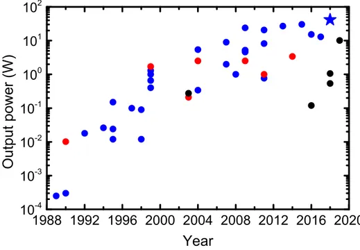
wave-length. During the last 20 years, 3 µm fluoride fiber lasers and their components have made significant progress and still maintain a high potential for further improvement. While the CW and pulsed output powers of the first version of such lasers were µW-level and their peak power was watt-level, respectively [9;53], today more than 40 W of CW power and 100 kW of peak power is possible thanks to advances in this research field. The evolution of the reported CW output power of 3 µm fluoride-based fiber lasers as a function of time is shown in Fig.
I.1, where the output power shows an exponential increase as a results of the growing interest in aiming to achieve higher output levels.
In this PhD project, fluoride fiber laser systems operating near 3 µm based on different active media and approaches and their critical in-fiber components to achieve high output power, efficiency and peak power were investigated. Although Fig.I.1presents an exponential increase in output power, demonstration of higher output power at 3 µm becomes more challenging due to limits related to the development of the components as well as the physical and chemical properties of fluoride glasses. One of the major challenges is the fluoride fiber tip degradation due to OH diffusion, a phenomenon limiting the maximum output power, was also studied by the fabrication of the novel endcapping components within the scope of this study.
The introduction part of this thesis briefly describes the main components of fluoride fiber
1988 1992 1996 2000 2004 2008 2012 2016 2020 10 -4 10 -3 10 -2 10 -1 10 0 10 1 10 2 O u t p u t p o w e r ( W ) Year
Figure I.1: Output power from fluoride fiber lasers based on Er3+(blue), Ho3+(red) and Dy3+
(black) gain media operating near 3 µm in CW mode as a function of time. Star, published through this thesis. Data points were taken from [9; 10;11;12;13;14; 15;16;17;18;19;20;
21;22; 23; 24;25;26; 27;28;29; 30; 31;32;33; 34;35;36; 37; 38;39;40; 41; 42;43; 44; 45;
46;47;48;49;50;51].
lasers, the schemes for generating 3 µm emission from rare-earth doped fluoride-based fibers, the major high-power based problems and promising methods to solve such problems. The work presented in the first chapter resulted in the demonstration of the highest efficiency diode pumped single-mode fluoride fiber laser operating near 3 µm. The second chapter presents a pulsed 3 µm laser amplifier which achieved the highest pulse energy and average power obtained from a sub-ns fluoride fiber amplifier. In Chapter 3, another simple diode pumped single-mode laser cavity is demonstrated which emits the highest CW output power around 3 µm ever achieved from a fiber laser. In Chapter 4, performances of the different endcapping components are discussed and a novel method to suppress OH diffusion in fiber tip is proposed.
I.2
Applications of 3 µm laser sources
The spectral region around 3 µm offers many advantages for different applications types in many areas. This section summarizes the most promising applications for 3 µm laser sources and, more specifically, for 3 µm fiber based sources.
Medicine
Laser sources based on different technologies and spectral ranges are already widely used in various medical applications as a replacement of traditional surgical tools. Moreover, laser radiation around 3 µm has great potential for such applications. Water is the dominant con-stituent in the human body and the fundamental stretching vibration of OH bond is located near 2.94 µm. Therefore, radiation is effectively absorbed by bio-materials and enables small penetration depths and precise bio-processing with minimal thermal damage and coagulation zones. The absorption spectrum of water is shown in Fig. I.2, in which at 2.94 µm peak, the absorption coefficient is 13300 cm-1.
CO2 lasers still popular for medical applications especially in cosmetic tissue surgery due to
high water absorption around their operating wavelength of 10.6 µm. Then, bulk Er:YAG systems operating at 2.94 µm have started to replace CO2 lasers given water absorbs ten
times more at 2.94 µm than at 10 µm. Additionally, their shorter pulse duration leads to less thermocoagulative damage. Today, Er:YAG lasers at 2.94 µm are used in different medical applications such as lithotripsy [54], dentistry [55], ophthalmology [56], biopsy [57], osteotomy [58], otolaryngology [59], dermatology [60], angioplasty [61]. In general, high-power CW and pulsed 3 µm lasers are used for hard tissue applications such as bone or dental processing; low power ones are prefered for soft tissue applications such as skin processing. Despite the fact that there are several parameters which affect the laser-tissue interaction, the types of mechanisms are classified as photochemical, thermal, photoablation, plasma-induced ablation or photodisruption [62]. Depending on the laser power, energy density and interaction time, the effect on the tissue varies. For instance, tissue heating occurs at low power densities (100 W/cm2), tissue evaporation (100-108 W/cm2), plasma and rear shock waves (109-1015
0 2 4 6 8 10 12 14 16 18 20 0,01 0,1 1 10 100 1000 10000 A b so r p t i o n ( 1 / cm ) W avelength ( m)
Figure I.2: Absorption spectrum of liquid water. Figure extracted from [67].
W/cm2) appear at higher power densities [63]. On the other hand, laser exposure time is
crucial to control all the applications by affecting the process quality. While plasma-induced ablation, photo-disruption and ablation occur for pulses shorter than 1 ns, photo-chemical and thermal interactions take place in CW or microsecond regimes [62]. Hence, the pulse duration has an effect on the resulting process. Er:YAG systems enable pulse durations lasting dozens of nanoseconds which is longer than the thermal relaxation time of water in biological materials. There are many medical applications requiring shorter pulses around 3 µm such as optical or corneal transplant surgery and stapes surgery. Such applications were realized by using optical parametric generation (OPG) based on solid-state laser architectures [64; 65]. Recently, cold vaporization of tissues by using picosecond pulses at 2.94 µm was also demonstrated and it shows that 3 µm ultrafast lasers have a great potential for damage-free medical applications [66].
The requirements of different laser parameters for medical applications shows that fiber lasers operating at 3 µm also have a great potential as clinical tools thanks to their advantages such as high beam quality, high efficiency, small foot-print and rugged design. The interaction of the laser output from a fiber laser with biomedical materials has been already studied and the clinical use of such systems has been tested by different research groups. A CW Er3+,Pr3+
fiber laser operating at 2.71 µm was used to ablate chicken and liver tissues. It was shown that laser processing is possible without carbonisation or charring [68]. Cutting capability of 3 and 2 µm cascade fiber lasers was demonstrated on soft rabbit tissues and enabled a precise cutting [23; 69]. On the other hand, rare-earth doped fluoride fiber lasers could be used with proper mirrors to achieve laser emission at a specific wavelength around 3 µm, which provides
precise control of the penetration depth of processing. For example, in Er3+-based media with
proper mirrors the laser wavelength could be selected from 2.7 µm to 3 µm and this range could even be extended up to 3.3 µm by using Dy3+ dopants. On the other hand, especially
for high-power short pulse 3 µm medical lasers, fiber technology plays an important role by serving as an amplifier to improve power levels. In Chapter 2, a high-energy picosecond fiber laser amplifier operating at 2.85 µm which has the potential to be used in medical applications, thanks to its sub-ns pulse duration and high pulse energy, is demonstrated.
Spectroscopy
Most of the atmospheric gases showcasing high absorption caused by fundamental vibration bands are located in the mid-IR spectral region, especially from 3 to 5 µm. Hence, laser sources operating in the mid-infrared range are required for spectroscopy, trace gas detection and mon-itoring applications with high temporal and spectral resolutions. Fig.I.3shows the absorption lines of important gases located between 2.5 and 5 µm. In this region, the absorption line strength of many gases is much stronger than their short-wave counterparts. The detection of the molecular species is realized by using tunable lasers such as difference-frequency genera-tion systems (DFG), optical parametric oscillators (OPOs), quantum cascade lasers (QCLs), inter-band cascade diode lasers (ICLs) or distributed feedback lasers (DFB).
The detection of species around 3 µm can also be realized by using tunable ZrF4 fiber-based
systems. A tunable dysprosium-doped ZBLAN fiber laser from 2.95 to 3.35 µm was demon-strated by Majewski et al. and the tuning range covers the molecular absorption of OH, NH and CH-based molecules located around 3 µm [70]. In this system, another 3 µm-class Er3+:ZrF
4
fiber laser was used as a pump source. In addition to this, an electronically controlled swept-wavelength laser using a dysprosium ZBLAN fiber and an accousto optic filter was used for real-time remote sensing of ammonia gas by Woodward et al. [71]. In this work, an Er3+:ZrF
4
fiber laser at 2.83 µm was used as a pump source and a sweep range of 360 nm (2.89 to 3.25 µm) was achieved.
Supercontinuum fluoride fiber laser sources are ideal candidates for broadband spectroscopy applications due to their longer wavelength extent range against silicate-based versions that have limited transparency. Generally, in order to broaden the spectrum, ZrF4fibers are pumped
by 2 µm or 1.55 µm pulsed sources [72; 73]. Then, advances in pulsed 3 µm OPG systems enabled the generation of supercontinuums with larger conversion efficiencies given their larger quantum efficiency. A supercontinuum extending up to 4.1 µm with 82% of its energy above 3 µm was demonstrated by seeding an Er3+:ZrF
4fiber with ps-level pulses at 3 µm from an OPG
[74]. It was also shown that the spectral coverage could be extended up to 5.2 µm by using indium fluoride (InF3) fibers [75]. Today, 3 µm fluoride fiber lasers provide high peak powers
with short pulse duration and have the potential to replace OPG sources as a seed sources and have an indirect advantage by enabling efficient and small footprint systems. Recently,
Figure I.3: Absorption spectra of important trace gases in the spectral region between 2.5 and 5 µm. The molecular line data is compiled by spectralcal.com online modeling using HITRAN database [67].
it was shown that, 3 µm ZrF4-based fiber laser systems have the ability to be mode-locked
at fs or ps pulse duration with tens of kW peak powers [76; 77]. Moreover, seed signal at 2 or 3 µm provided by solid-state based or mode-locked lasers are coupled into the fiber by free-space coupling which causes losses and parasitic processes. Hence, the advance of 3 µm ultrafast fiber laser systems will have the potential to provide reliable monolithic fiber-based supercontinuum sources in the near future.
Defence & security
The spectral region between 3 and 5 µm has great importance for the monitoring and tracking of aerospace vehicles since the atmospheric transmission is maximum and detectors used in such vehicles are sensitive in this region. On the other hand, in the operation, hot parts of the aerospace vehicles such as the rotor, fuselage and nozzle reach temperature between 600-700 ℃, which is the thermal signature of black body emission located between 3 and 5 µm [78]. Thus, efficient laser sources operating between 3 and 5 µm are necessary to achieve countermeasure systems against heat-seeking missiles. The laser could have a broad spectral width which covers the atmospheric transmission window or short width which tunes rapidly across the wavebands and should have a beam close to the diffraction-limit [79]. The effective modulation rate of the laser source is also important, especially for jamming new generation missiles [80]. For 3-5 µm countermeasure systems, ZrF4-based fiber lasers are potential candidates given their high
I.3
Fluoride fiber laser components
The evolution of the fluoride fiber laser technology considerably depends on the advances of optical components working in the IR spectral region. The components used in mid-IR fiber lasers have progressed in the last 10 years leading to stable, long-term operation of high-power fiber laser systems operating around 3 µm. Despite this, fluoride fiber-based laser technology still lacks stable, high-power components compared to silica-based technology and has been advancing rather slowly due to the poor thermo-mechanical properties of fluoride glasses.
The main components for a 3 µm fiber laser system can be listed as, the fluoride-based fiber, the fiber Bragg gratings (FBGs), the pump sources, the splices and the endcaps. Fluoride fibers have been used for more than 20 years in laser systems and their manufacturing has been progressing. Using appropriate fluoride fibers for laser systems is critical to obtain the required laser emission parameters. Therefore, geometrical and chemical properties of the fiber are determined prior to the manufacturing process by numerical simulations. FBGs simplify laser cavities by serving as a wavelength selective mirror in the fiber core and their fabrica-tion in fluoride-based fibers is now possible [81]. Pump sources are the essential components for exciting the laser medium and choosing a proper pumping wavelength depending on the lasing mechanism is vital. The fused glass components, namely splices and end-caps also play an important role for laser cavities to ensure their reliability and efficiency by providing a higher damage threshold and increased resistance to OH degradation. State of-the-art heat sources are necessary for achieving a junction between two fibers and the development of endcapping components. The procedure with non-oxide-based fiber glasses is more difficult than with oxide-glasses because of low glass transition temperature and mechanical proper-ties of non-oxide fiber materials. Hence, different novel approaches and state-of-the-art fiber splicing technologies are necessary to achieve low-loss fiber junctions and components between fluoride-based fibers, as well as fluoride to oxide-based fibers.
In this section, the role of the main fluoride fiber laser components and the development of in-fiber components used in 3 µm-class fiber lasers are explained.
I.3.1 Fluoride-based fibers
Fluoride-glass fibers are the core components of 3 µm fiber lasers and amplifiers, thanks to their excellent mid-IR transparency compared to silica fibers. They are the member of fluorozirconate glass family, which were reported for the first time by M. Poulain et al. in 1975 by observing ZrF4-BaF2-NaF ternary systems [82]. Then, ZBLAN, the most popular and
stable member of this family composed of ZrF4, BaF2, LaF3, AlF3 and NaF was reported [83].
Given such glasses are mainly composed of ZrF4, they are often called ZrF4-glass fibers or
The low phonon energy of such glasses (580 cm-1 for ZBLAN [84]) leads to metastable states
when they are doped with rare earth ions. They are highly soluble which enables highly con-centrated doping of rare-earth ions up to 10 mol.% [84]. Therefore, it is possible to obtain laser output by using short-length of highly-doped ZrF4-based fibers. Moreover, as a result of their
low phonon energy, the theoretical attenuation of such fibers around 3 µm is less than 1 dB/ km. Currently, it is possible to find commercially available ZrF4-based fibers with background
propagation losses less than 60 dB/km at 2.9 µm [44], which is far from the theoretically pre-dicted minimum loss of fluoride fibers (< 0.01 dB/km) [85]. The attenuation behaviour of a single-mode ZrF4 (Le Verre Fluoré) and a low-OH SiO2 fibers (Centre d’Optique, Photonique
et Laser) up to 4.5 µm is shown in Fig. I.4.
Although their excellent properties for mid-IR transmission and their low phonon energy, ZrF4 fibers present several disadvantages compared to SiO2 fibers. Before the fiber
manufac-turing process, choosing the right fiber according to required laser specifications is necessary. Determining geometrical and optical properties, such as core-clad ratio, clad shape, NA, chem-ical properties, rare-earth dopant and its concentration, is achieved by numerchem-ical simulations. During the manufacturing process, point defects due to impurities and imperfections such as bubbles, micro-crystals, core-clad boundary fluctuations could be formed due to the high level of transition metals and OH impurities. These defects cause scattering spots or absorptive losses and may restrict the output power, therefore resulting in catastrophic failures along the fiber. Thus, prior to the experimental work, it is required to screen fluoride fibers in
or-1000 2000 3000 4000 0 50 100 150 200 A t t e n u a t i o n ( d B / km ) W avelength (nm) Low OH-silica ZrF 4
der to locate possible point defects on the fiber segment and reduce the occurrence of fiber failure during laser experiments. In order to verify geometrical properties, manufactured fiber segment from both end faces should be inspected by microscope. The smaller binding energy of ZrF4-glass causes mechanical fragility (e.g. the strength of ZrF4 fibers is less than 1 GPa
[86], while it is 12 GPa for the silica fibers [87] and the theoretical mechanical strength of fluoride fibers is 40-50 % of silica fibers [88]) and poor resistance to environmental attacks. This is because of the nature of the fluoride-based glass in which Zr-F bonds are much weaker than Si-O bonds. For this reason, handling of such fibers is extremely challenging and re-quires special care during the splicing, FBG writing and laser assembling procedures. The low transition temperature (265 ℃ [89]) and low melting temperature (340 ℃ [90]) of such fibers is another potential problem for stable laser operation. Therefore, monitoring the fiber temperature during high-power laser operation is crucial to prevent against possible thermal catastrophic damages. The small difference between melting and transition temperature also requires precise heating during the splicing procedure of ZrF4 fibers to avoid crystallization.
Fluoride glass optical fibers have been studied extensively after their discovery and their mechanical properties and repeatability of manufacturing have made tremendous progress especially in the last 10 years. It is possible to fabricate them in different geometries with a well-controlled core/clad eccentricity. Today, it is possible to find fluoride fibers with different geometries on the market. Their core diameter ranges from few-µm diameter to 900 µm. The NA ranges from 0.05 to 0.40 and the clad type can be designed single or double clad with hexagonal, square, cylindrical or double-D shape geometry. Their thermal expansion coefficient varies from 140 to 220×10-7K-1[91] and refractive index can be modified from 1.43
to 1.60, which provides relatively low Fresnel losses compensates other mid-infrared glasses. Nowadays, polarization maintaining (PM) versions with ellipsoidal core and active versions with different dopant ions, such as Er3+, Pr3+, Ho3+, Dy3+, Ce3+, Tm3+, Nd3+, etc. can also
be manufactured [92;93].
In addition to ZrF4-based fluoride fibers, AlF3- and InF3-based fluoride fibers are commercially
available and widely used in different areas. AlF3 fibers contain higher molar concentrations of
AlF3 than ZrF4 fibers and their transmission range is not as wide as ZrF4. Despite this, they
have enhanced chemical durability and strength than ZrF4 fibers [94] and the glass transition
and melting temperature of AlF3-based bulk glasses are 392 ℃ and 650 ℃, respectively [95],
which are higher than for ZrF4. Thanks to their higher durability against moisture, better
mechanical properties and higher damage threshold, they are mostly used as delivery cables for Er:YAG and Er:YSGG lasers used in medical applications, and for capping component for fiber faces in high-power fluoride fiber lasers.
InF3-based fibers are another type of fluoride-based fibers, providing more than 1 µm wider
spectral transmission (up to 5.5 µm [88]) than ZrF4. They also have slightly higher glass
in supercontinuum sources. The first InF3-based supercontinuum source with a spectrum
ex-tending beyond 5 µm has already been demonstrated [75]. On the other hand, by using an InF3-fiber as a host and doped with Dy3+ ion, fluorescence emission beyond 4 µm was also
shown for the first time [96].
Lastly, since all types of fluoride-based glasses are highly reactive with liquid water, their uncoated parts should be isolated from the atmosphere in a protected moisture-free ambient enclosure purged by a noble gas such as nitrogen. Under other conditions, two of the glass components, ZrF4 and BaF2 start to dissolve by the atmospheric water; then the properties
of glass matrix change by penetration of the water into the glass; lastly ZrF4 crystals growth
on the glass surface is observed after a certain time [97;98].
I.3.2 Fiber Bragg gratings
FBGs are fabricated through periodic perturbation of the refractive index of the fiber core. Instead of using bulk mirrors, FBGs enable to achieve a simple, rugged and monolithic laser architecture. The grating period and the change in refractive index are the main parameters which determine the Bragg wavelength based on the following formula:
λ = 2neffΛ, (1)
where λ is the vacuum wavelength, neff is the effective refractive index of the fiber mode
and Λ is the period of Bragg grating. In principle, the manufacturing method is based on exposing the fiber core by using an intense light source such as a laser. Depending on the fiber and the exposure pattern, the refractive index increases or decreases with a fixed index modulation. The refractive index profile of the FBGs can be tailored in order to achieve different designs which can be either uniform, chirped, tilted, discrete phase shift or Gaussian apodized, and superstructure based on targeted laser architecture and output laser parameters. FBGs are used in communication and sensing systems such as wavelength filters, optical add-drop multiplexers, dispersion compensators, temperature and strain sensors. In fiber laser applications, they are used as wavelength selective mirrors for laser cavity by restricting the emission wavelength to a specific range. The techniques for manufacturing FBGs vary but the most common are holography, phase-mask, and point by point writing techniques.
FBGs in mid-IR fiber lasers enabled to achieve monolithic laser architectures and led to enhanced efficiency and output power. They are key components for a stable high-power laser emission from a rugged laser cavity and their optimization is crucial for limiting photo-induced losses at laser and pump wavelengths. Prior to FBG technology the output power level of fluoride fiber lasers at 3 µm were limited to 5 W-level [29]. Such systems were not robust and compact, and efficiencies were lower and output spectra were not stable. The use of FBGs in ZBLAN fiber core provided precise spectral control of the gain which led to the achievement
of record output power levels. Fiber laser cavities, in general, are bounded by a high reflective FBG (HR-FBG) and a low reflective FBG (LR-FBG). The reflection bandwidth of HR-FBG is generally chosen to be broader than LR-FBG; however it might change depending on laser configuration and fiber type.
For inscription of FBGs into the core of the fluoride-based fibers, different methods have been used until now. First, the photo-sensitivity of fluoride-based fibers has been investigated on Ce3+-doped ZBLAN fibers by writing 1560 nm FBGs in fiber core through UV illumination
at 246 nm [99; 100]. The demonstration of refractive index change in various bulk glasses by using femtosecond pulses at 800 nm has benefited the FBG writing process [101]. Firstly, optical waveguides were written in ZrF4-based glasses by using 800 nm fs pulses [102]. Then
the phase-mask-based FBG writing procedure in single and multimode fluoride fibers by using 800 nm fs pulses was demonstrated for the first time [103; 81]. In this technique, the laser beam is focused on the fiber core through a mask and the distance between the phase-mask and fiber is chosen carefully to ensure propagation of zero-order pulses through the fiber core precedes other orders. Moreover, this technique allows mass production and the grating period is not dependent on the wavelength of the writing source and is less depended on the incident beam angle. The coherence of the laser source is also less critical and the period of the grating is determined only by the period of the mask. After that, a watt-level ZBLAN fiber laser operating at 1480 nm including FBGs based on the phase mask method written by 800 nm femtosecond pulses was reported for the first time [104]. Another FBG writing technique named as point-by-point (PbP) was used in fluoride fibers for the first time and a single-mode fiber laser operating at 2914 nm including such FBGs was demonstrated [105]. In all demonstrations above, it was necessary to strip the fiber polymer before and recoat by using appropriate polymer and UV source after the writing process. This approach is time-consuming and limits the FBG yield because it reduces the mechanical strength of the fiber. By an appropriate focusing configuration, writing FBGs through the silica fiber’s coating was demonstrated for acrylate and polyimide coatings [106]. This technique was applied on fluoride and silica fibers to demonstrate high-power laser outputs [107; 108; 109]. The same approach without using a phase mask was also used into a single-mode fluoride fiber core and a wavelength tunable from 2850 nm to 2887 nm FBG-based fluoride fiber laser was demonstrated [110]. Goya et al. also demonstrated a plane-by-plane femtosecond FBG inscription process by using 517 nm pulses, without removing the fiber coating and they studied spectral and output power behaviour of the laser system at 2.8 µm [111]. Another method, named tilted fiber Bragg grating technology, was used by Bharathan et al. to write 45°-tilted FBGs into passive and active fluoride fibers and the polarization properties of such FBGs were evaluated [112].
In this project, all the FBGs used in the laser cavities were fabricated by using 800 nm fs pulses with the phase mask technique described in [81] and in [106]. The pulse energy of the
laser source was around 1 mJ at 1 kHz of repetition rate. Especially for high-power lasers, a characterization procedure of the FBGs is required. ZrF4-based fibers show poor thermal
stability after FBG writing process due to their low glass transition temperature. Depending on the maximum core temperature in laser operation, thermal annealing is necessary to sta-bilize FBGs’ spectral response under the high-power pumping and lasing operation, and to lower losses coming from the inscribed part of the fiber. For example, as shown in the article presented in Chapter 3, a heavily-doped fiber laser cavity was used to achieve 41.6 W output power at 2.8 µm. In this work maximum temperature of fiber core under the maximum pump power was calculated to be 150 ℃ and FBGs were annealed according to this calculation for ensuring their long-term stability. FBGs were annealed at 150 ℃ for 10 min for improving their spectral response at high temperature. On the other hand, due to the annealing process, a decrease in refractive index modulation of FBGs is expected, therefore keeping the index mod-ulation large enough for the HR-FBG is crucial before the annealing process. The reflectivity of the FBGs is chosen depending on the gain medium. For example, if the lasing wavelength is far from the peak gain of the dopant material, a higher reflectivity output FBG is required to reduce the lasing threshold. On the other hand, in high-power 3 µm laser cavities, spectral overlap between HR- and LR-FBGs is necessary to ensure stable laser operation.
I.3.3 Pump sources
The pump laser sources exciting the gain medium are fundamental components of fiber laser sources. To generate 3 µm laser emission by using different rare earth ions, choosing the opti-mal pump source parameters depending on absorption and energy transfer characteristics of the gain medium is required. The operating mechanism of laser diodes is based on pumping of p-n or p-i-n junctions electrically. Fiber coupled GaAs-based semiconductor laser diodes with single or multiple emitters are widely used as pump sources in fluoride fiber laser ar-chitectures thanks to their high efficiency and output power, as well as their low numerical aperture (NA), low threshold current, long lifetime, compactness and robustness. Such fea-tures of semiconductor laser diodes have made great contributions to the advancement of fiber laser technology. Especially for high-power laser applications, the efficiency of the laser diode is a crucial parameter for the non-stop industrial applications.
There are essential parameters in order to ensure an efficient laser pumping. First of all, for fiber-coupled fiber laser diodes, if a splice between the pump and laser cavity is required, the NA of the pump source should be matched with that of the cavity fiber for efficient pump light coupling. The pump wavelength should cover the absorption band of the active ion sufficiently with suitable pump energy for inducing the laser transition. In addition, its bandwidth should be chosen depending on the medium. The pump energy and spectral noise is another factor which affects the laser output power stability. The brightness of the pump source has an effect on the efficiency and compactness of the optical design so it is critical to use high-brightness
pumps to have a stable and short gain media.
Most of the multi-mode semiconductor pump laser diodes have the tendency to shift their central wavelength to longer wavelengths, as their temperature and charge density increase [113]. Increasing the electrical current of such diodes, to obtain higher pump power levels, increases the junction temperature, which causes a shift in wavelength. The wavelength shift parameter of laser diodes is provided by the manufacturer and is around 1 nm/A in general i.e. proper cooling conditions are respected. The change in wavelength during the laser operation affects the photon transfer mechanism in the active medium, especially if the medium is heavily doped, and might create slope efficiency problems. For instance, in Er3+:ZrF
4 fibers,
the pump source operating around 975 nm is absorbed by ground state absorption (GSA) (4I
15/2 →4I11/2), which is the higher energy level of the 3 µm laser transition. Absorption via
excited state absorption (ESA) on the4I
11/2 →4F7/2 transition (e.g. Fig.I.7) is also observed.
GSA and ESA have similar cross-sections around such pump wavelength and ESA might limit the output power because it lowers the number of ions in the higher laser transition level (4I
11/2). In addition, after the absorption of ions to the4F7/2 level by ESA, they are recycled
to 4I
11/2 level by subsequent multiphonon relaxation, which increases the core temperature.
Hence, choosing a proper pump source wavelength or optimizing the wavelength by changing the diode temperature, where ESA is the lowest and GSA is the optimum, to keep the fiber temperature minimum and slope efficiency maximum, is important. Numerical simulations show the optimum wavelength for pumping this system is located around 983 nm [114]. Today, precisely controlled wavelength stabilized diodes based on volume Bragg gratings (VBGs) are commercially available at high output power levels and could be used instead of diodes with an unstable broad spectrum.
On the other hand, the central wavelength of some pump sources to use in 3 µm laser cav-ities might not be commercially available or be power limited. For instance, in singly doped Ho3+ZrF
4- or co-doped Ho3+, Pr3+-based systems, 3 µm is generated from the 5I6 → 5I7
transition. The direct excitation of the5I
6 level is possible by GSA around 1150 nm. However,
diodes operating at such wavelengths are power limited although Yb-silica or Raman fiber lasers operating around 1100 nm can be used as a pump source [115; 43]. Similarly, in-band pumping of Dy3+-doped fluoride fiber laser emission around 3 µm through pumping with
an-other fiber laser source operating around 2.8 µm, which is not commercially available, was reported [51].
To sum up, pump sources have a critical importance for the lasers and amplifiers and their optical parameters should be considered during the laser design.
I.3.4 Fluoride fiber splices
Fiber splicing of two fibers is one of the most important fabrication steps of the development of fiber lasers. The aim of the splicing process is to achieve a compact laser architecture with higher transmission efficiency with reduced parasitic lasing. Two methods, mechanical and fusion splicing, are generally used. In the mechanical splice method, fibers are not permanently joined together, instead they are just held together in a precisely aligned position. For this reason, insertion loss is higher than the fusion splicing method along with the significant reduction of the mechanical robustness. In the fusion splicing method, the glass faces are fused together by using a filament, laser or electric arc discharge; hence the connection between the fibers enables low insertion losses and ensure high mechanical robustness.
Splicing of silica fibers is easy and well-known because of their high mechanical strength and large difference between the melting temperature and crystallization temperature of silicate glass. On the other hand, fluoride to silica splices are difficult because of their significant chemical composition difference and softening temperature contrast (265 ℃ for fluoride, 1175 ℃ for silicate [89]). In addition, the temperature range for changing from solid to liquid phase has an effect on achieving a good quality splice. However, this range for ZBLAN fibers is around 90 ℃, while it is more than 300 ℃ for silica fibers [116] so precise control of the splice temperature is essential for a good quality splice involving between fluoride fibers. Moreover, especially in high-power laser operation around 3 µm, splice losses should be kept quite low because fiber protecting coating based on low index fluoro-acrylate polymers has high absorption around 3 µm. The heat control precision of the fusion area varies according to the heat source technology. In 1976, splicing by electric arc was shown for the first time and then arc splicers have made great progress [117]. The arc splicers are based on creating a heat zone by a current flow generated between two electrodes. The generated temperature by such technology is generally high (>1000 ℃) and turn-on and -off characteristics of arc discharges lack of precise control. Nowadays, arc splicers with three electrodes technology provide a wide plasma area with more controlled temperature and zone area, allowing to splice ZrF4
fibers to each other. Fusion splicing of fluoride fibers was also achieved by using CO2 lasers
in laboratory environment [118]. Then splicers with absorptive CO2 laser-based process was
developed recently, and have been used for splicing of fluoride-based fibers, as well as for silica fibers [119]. With commercially available laser glass processing stations, the temperature can be precisely adjusted and distributed uniformly. Besides such technologies, another common splicing method consist of using a filament-based splicer because it can achieve well-controlled heat region and over time duration ability of tungsten filament. In a very short heating time, the temperature of the fusion zone can be changed during the splicing process, which enables repeatable splicing recipes. In all technologies, ambient conditions such as atmospheric OH, temperature, dust, may affect the heat source and fusion splice by causing crystallization of the ZrF4 fiber. Thus, for the protection of the heat source and the fiber, a low vacuum or high
purity noble gas ambient environment is required during the splicing process.
During the splicing procedure, the preparation of the tip of the fluoride fiber must be realized correctly to minimize the transmission losses without degrading the quality of the beam. There are several steps to achieve a dust-free, low-loss fluoride to fluoride fiber splices. The first step involves removing the acrylate coating from the fiber glass by using chemicals such as dichloromethane. After applying the chemical materials, the coating of the fiber could be removed by using lint-free wipes with isopropyl alcohol or acetone. Remaining particles from the polymer and dust should be completely eliminated from the stripped glass surface. Then the fiber is cleaved by creating a crack propagating through the fiber until it breaks by using a blade with applying a controlled tension along the length of the fiber, which depends on the fiber diameter and material [120]. The accuracy of the applied tension on the fiber has an effect on the quality of the fiber end face and it is important to maintain a low tension variation during the cleave process. There are industrial cleavers in the fiber optics market such as the Fujikura CT-104, Vytran LDC 401, Nyfors LDF-M providing adjustable tension with small variations. The angle of the cleave should be close to zero degree, while the shape of the fiber end should be crack-free for increasing the chance of achieving low-loss fusion splices. Then, parameters of the splicer such as splice power, hot push distance of the fibers, offset values of heat source, the gap between the fibers and splice time are optimized. The splice results of fluoride-based fibers can be considerably affected by small changes of such parameters, especially the amount of heating and temporal behaviour of the heat source, due to their small phase change temperature difference from solid to liquid. Especially in single-mode to single-single-mode fluoride fiber splices, it is crucial to choose these parameters precisely to preserve the alignment of the fiber cores during the heating process.
After determining the parameters, two fibers are aligned together either core to core or clad to clad depending on the type of splice. Then, a heat zone generated by an electric arc, laser absorption or a filament, is applied to the gap between two fibers or at a different position depending on the fiber types. The last step of splicing is to test the mechanical strength of the splice point by measuring the tension up to a safe value and measure the transmission losses at the operating wavelength.
One of the most critical splice types is fluoride to silica fibers because it allows achieving monolithic 3 µm fiber laser systems [44;50] by eliminating free space pump coupling, namely allowing to create a junction between fiber output of the pump source and fluoride fiber of the laser cavity. However, the large melting temperature mismatch between fluoride and silicate glasses makes it difficult to achieve. In recent years, many different works have been realized to develop methods for splicing a fluoride to a silica fibers but there is still room for improvement. After achieving a low-loss splice between two different fibers based on different materials by NP Photonics, Inc. [121], many attempts were demonstrated to achieve ZBLAN to silica fiber


![Figure I.9: Cross-section spectra of GSA and ESA in Er 3+ fluoride glass. Figure retrieved from [142].](https://thumb-eu.123doks.com/thumbv2/123doknet/3175907.90636/42.918.198.717.110.459/figure-cross-section-spectra-fluoride-glass-figure-retrieved.webp)