Any correspondence concerning this service should be sent to the repository administrator:
[email protected]
To link to this article:
DOI: 10.1016/j.surfcoat.2017.08.061
URL: http://dx.doi.org/10.1016/j.surfcoat.2017.08.061
This is an author-deposited version published in:
http://oatao.univ-toulouse.fr/
Eprints ID: 18564
To cite this version: Tendero, Claire and Lazar, Ana-MAria and Samélor, Diane and
Debieu, Olivier and Constantoudis, Vassilios and Papavieros, George and Villeneuve,
Aurélie and Vahlas, Constantin Nanocomposite thin film of Ag nanoparticles embedded
in amorphous Al 2 O 3 on optical sensors windows: Synthesis, characterization and
targeted application towards transparency and anti-biofouling. (2017) Surface and
Coatings Technology, vol. 328. pp. 371-377. ISSN 0257-8972
O
pen
A
rchive
T
oulouse
A
rchive
O
uverte (
OATAO
)
OATAO is an open access repository that collects the work of Toulouse researchers and
makes it freely available over the web where possible.
Nanocomposite thin film of Ag nanoparticles embedded in amorphous
Al
2
O
3
on optical sensors windows: Synthesis, characterization and
targeted application towards transparency and anti-biofouling
C. Tendero
a, A.-M. Lazar
a, D. Samélor
a, O. Debieu
a, V. Constantoudis
b,c, G. Papavieros
b,c,
A. Villeneuve
d, C. Vahlas
a,⁎
aCIRIMAT, 4, allée Emile Monso, BP-44362, 31030 Toulouse Cedex 4, France
bInstitute of Nanoscience and Nanotechnology, NCSR Demokritos, Neapoleos 10, 15310 Ag. Paraskevi, Greece cNanometrisis, ΤEPA Lefkippos, Patriarchou Grigoriou & Neapoleos 27, PO Box 60037, 15341 Agia Paraskevi, Greece dANDRA, 55290 Bure, France
a b s t r a c t
Increased motivation for environmental monitoring requires robust and reliable sensors. The present work aims at increasing the service time of optical sensors immersed in riverine waters by decreasing the development of biofouling on their surface. In this aim, nanocomposite coatings composed of metallic silver nanoparticles em-bedded in an amorphous alumina are co-deposited on sensor glass windows by chemical vapor deposition. Im-mersion for one week in the Saulx river, France, revealed a threefold decrease of biofouling on their surface compared with untreated glass surfaces while maintaining transparency. Such coatings can be considered as part of integrated tools, including for example mechanical cleaning, to reduce the maintenance of optical sensors immerged in riverine waters.
Keywords:
Antibiofouling coatings Transparent coatings Optical sensors Chemical vapor deposition Amorphous alumina Silver nanoparticles
1. Introduction
The protection of environmental sensors is an important issue in so far as such sensors have to operate continuously and autonomously during several months to collect high quality data[1]. In the case of im-mersed marine and riverine sensors, aquatic biofouling; i.e. microbial adhesion and biofilm formation, decreases the operating lifetime and increases the cost of maintenance of the sensor, since the sensor must be removed from the sampling location to be cleaned.
Particularly, in the case of optical sensors which are often imple-mented to monitor turbidity and nutrients such as chlorophyll, biofoul-ing is one of the most prevalent hindrances to long-term, continuous, and in situ optical measurements because build-up of residue on the op-tical window causes degradation of measurement signals over time, hence reducing measurement accuracy[2]. The degradation of the opti-cal performance in short time period spanning from days to months has been a concern since more than twenty years[3,4], resulting in the de-velopment of antifouling measures to prevent the deterioration of the optical window transparency of the sensor. Such measures may involve incorporation of some type of brush or wiper, however it should be
ensured that it will not scratch the optical surface. In this perspective, copper plates, tubing and shutters were proposed by Manov et al. to delay biofouling[5]. Chlorination resulting from either bleach injection or electrolysis[6]or the use of pressurized fresh water cleaning[7]have also been reported as means of chemical cleaning of sensors' lens and housing.
Anti-biofouling coatings may also be applied on the surface of optical lenses and windows as an alternative or complementary solution to the above ones[3]. In that case, the measurement medium and the sensor sensitive area must remain as much as possible unmodified. This im-plies that the coatings need to be transparent and to present low surface roughness to avoid erroneous measurements[2,5]. For sensors operat-ing in marine environment, these specifications have been met through the use of conductive, catalytic coatings composed of platinum, Pt and indium tin oxide, ITO[8]. In this report, the electrocatalysis capability of Pt/ITO is used for the generation of Cl2from NaCl in seawater,
with-out, however information provided on the transparency of the film. Al-ternatively, exposure of the optical instrument to ultraviolet radiation, UVR during short, though frequent maintenance periods can be used as a potential tool to control biofouling[9]. The authors report that in-tensity of UVR, but mostly duration of exposure in an hourly cycle (thus impacting operation time) are the most critical parameters to slow down the development of biofouling. Delauney and Compère[1]
⁎ Corresponding author.
and more recently, Zhang and Zhang[10]compiled the various lens-cleaning techniques which have been studied by academia and optical sensor manufacturers.
Anti-biofouling coatings on glass windows immersed in riverine or continental water remain poorly developed up to now. Such coating ar-chitectures designed on purpose may include biocide nanoparticles, (NPs hereafter), like silver, Ag, supported on, or embedded in an optical-ly transparent, smooth coating. This support may not onoptical-ly serve as a fix-ing medium of the Ag NPs. Indeed, Chang et al. reported that, in the case of an Escherichia coli bactericidal mechanism, unsupported Ag+ions did
not play an important role in the bactericidal process[11]. In contrast, when supported on gamma alumina, γ-Al2O3, a synergistic effect occurs
between Ag and γ-Al2O3, illuminating a bactericidal mechanism
pro-moted by catalytic oxidation. It is well known that the catalytic activity of γ-Al2O3is due to penta-coordinated Al3+ions which are located on
the surface of γ-Al2O3[12].
The authors group has developed various chemical vapor deposition, CVD processes for the production of amorphous alumina, a-Al2O3films
[13–15]. Such films, processed from aluminum tri-isopropoxide, ATI contain a large percentage of penta-coordinated Al3+ions, as was
dem-onstrated by27Al nuclear magnetic resonance, NMR spectroscopy[16].
The group also investigated CVD processes of nanostructured composite coatings containing Ag NPs embedded in a titanium dioxide matrix[17]. Based on this information, an original, one step CVD process is pre-sented hereafter which consists in the co-deposition of Ag NPs and of a-Al2O3. It is aimed the formation of a nanocomposite coating where
the Ag NPs are likely to ensure a biocide effect and the a-Al2O3matrix
stabilizes the NPs and serves as a catalytic support with limited, still ac-ceptable impact on transparency. The adopted architecture of the nano-composite coating consists in a first sublayer of pure a-Al2O3on the
glass window, followed by the major part of the coating, composed of Ag NPs embedded in a-Al2O3. In this architecture, the sublayer ensures
intimate contact with the glass surface and hence sufficient adhesion during the immersion tests; this is not the case for the composite film codeposited directly on the glass substrate. The main part of the coating serves as a reservoir of Ag NPs, which are exposed to the water through the evolving free surface during the lifetime of the low wear resistant coating. Indeed, the hardness H and the elastic modulus E of a-Al2O3
are 10.8 ± 0.8 GPa and 155 ± 6 GPa, respectively[18]. The resulting value of the elastic strain to failure H3/E2which is an indicator of wear
resistance[19]equals 0.05 GPa. While applications involving mechani-cal contact require materials with a tenfold higher H3/E2values, the
present one reveals a material which can be considered as sacrificial in low mechanical load operating environment, such as sediments-rich water flow. Such evaluation of a-Al2O3coatings is supported by recent
results, reporting that, when subjected to severe hydrothermal ageing, they are eroded resulting in the increase of their superficial roughness and porosity without, however affecting their adhesion on glass[15]. For these reasons, it is expected that applying a pure a-Al2O3sublayer
by the surface and loading a large external part of the host, a-Al2O3
coat-ing with Ag NPs, should be beneficial to the maintaincoat-ing of the expected anti-biofouling function of the surface and to the durability of the coat-ing on the glass window.
Coated and as received optical windows were tested by immersion in an area belonging to a large monitoring network of the surface water quality within the frame of long term environmental observatory (OPE) of the French national radioactive waste management agency (ANDRA). One of the rivers whose quality is monitored within the OPE is the Saulx river (GPS 48° 24′ 50″ N, 5° 21′ 35″ E). The in situ tests were conducted on a site located upstream the Saulx, at the Echenay village. This observatory has been designed by ANDRA to pro-vide a comprehensive and integrated description of the environment surface dynamics within the large Cigéo project (deep geological stor-age area of high level and long lifetime radioactive waste). The OPE is aimed at identifying environmental evolutions at relevant scales of space (local, regional or global) and to discriminate their origins
(natural, human activities…), in particular those from Cigéo. Relevant chemical and physical parameters as well as bio-indicators were identi-fied to properly describe the environment. These indicators require con-tinuous monitoring stations that are equipped with sensors. This work focuses on the protection of one of those commercial optical sensors (Bionef-BBE-Algae-torch) that measures relevant parameters such as the fluorescence intensity at 680 ± 100 nm of chlorophyll and cyanobacteria after excitation at 470, 525, and 610 nm.
The paper is organized as follows: the CVD protocol for the deposi-tion of the nanocomposite coating and the characterizadeposi-tion techniques, including the evaluation of biofouling, are first detailed. Then, the mi-crostructural characteristics of such coatings are determined. Finally, the optical transmission properties of the coated glass and the develop-ment of biofouling on the samples after immersion in riverine water are presented prior providing concluding remarks.
2. Materials and methods 2.1. Thin film deposition
Ag NPs were processed by direct liquid injection, DLI-CVD from sil-ver pivalate (CH3)3CC(O)OAg (namely AgPiv), by adapting a protocol
reported in[17]. The precursor solution was prepared by mixing AgPiv (Lotus Synthesis) and a solution of mesytylene/dipropylamine (Sigma Aldrich) (90/10 vol. respectively) inside a Schlenk flask, resulting in a 10− 2M AgPiv solution. Then, the Schlenk flask was connected with
the injection system and purged several times with pressurized N2
(99.9999%, Praxair, for all N2lines of the experimental setup). DLI of
the solution was carried out with a Kemstream Vapbox® system com-posed of two injectors connected in series. One gas line was connected to the Schlenk flask. The frequency and opening times (typically 1 Hz and 10 ms) of the injection system were controlled by a computer inter-face to feed the thermally regulated evaporation chamber with precur-sor solution microdroplets mixed with N2gas, having a flow set of
320 standard cubic centimeters per minute (sccm).
a-Al2O3, was deposited from ATI following a protocol reported in
[20]. ATI (N98%, Acros Organics) was melted in a bubbler above 413 K and then was maintained supercooled at 373 K. It was transported to the deposition zone by bubbling 30 sccm of N2(regulated, as for all
other gas lines by mass flow controllers) through the bubbler. The injected AgPiv solution, the vaporized ATI and an additional N2
dilution line flowing at 100 sccm were simultaneously introduced in a homemade horizontal hot-wall CVD reactor. All lines were heated at 373 K to prevent the condensation of precursors. The reactor is com-posed of a fused-silica tube (25 mm diameter, 300 mm length) heated by a resistive furnace. A dry pump and pressure gauges connected to the output of the fused-silica tube were used to control the deposition pressure to 5 Torr.
Four, 1 cm thick glass samples of the Bionef-BBE-Algae-torch com-mercial sensor external windows were placed on a row from Q1 in the beginning to Q4 at the end of the isothermal zone of the furnace. Silicon substrates (10 × 10 mm) cut from 4″ Si (001) wafers (Sil'tronix-ST), placed at intermediate positions, were also coated and used for TEM analysis. We have already demonstrated that the characteristics of a-Al2O3films are independent of the nature of the substrate, namely
AISI 304 L stainless steel (SS), (100) oriented Si wafers, and thermally grown silica on Si wafers[13]. All samples were cleaned in an ultrasonic bath with acetone and ethanol, and were immediately introduced to the reactor. Co-deposition was performed at 723 K for 31 min to reach submicrometric thickness (ranging from 300 nm to 200 nm for Q1 to Q4 respectively, estimated by reflectometry measurements). This tem-perature is suitable for the deposition of both Ag NPs[17]and a-Al2O3
films[20]from the two selected precursors. Prior codeposition, a thin film of pure a-Al2O3was deposited on the substrates surface with the
aim to enhance the adhesion, by feeding the reactor with ATI and the di-lution gas for 5 min, in the previously defined conditions. The deposition
process was terminated by first switching off either the ATI or the AgPiv flow so as to respectively obtain an Ag-rich surface to enhance anti-bio-fouling activity or an alumina-rich surface for the samples used for transmission electron microscopy, TEM (to ensure the integrity of the coating during cross section preparation).
2.2. Materials characterization and tests
Surface morphology was observed by scanning electron microscopy (SEM) on a LEO 435VP instrument. SEM samples were covered by a thin layer of sputtered gold to prevent charging effects. Atomic force micros-copy (AFM) was used in a tapping™ mode on an Agilent 5500 device to evaluate the roughness. Cross sections of the films deposited on Si were prepared by cutting the samples into two thin slices (normal to the in-terface coating/substrate) with a diamond wire saw. The slices were glued together, coating to coating, and embedded in a 3 mm diameter brass tube in an epoxy resin. After curing, the tube was sectioned into approximately 300 μm thick discs which were polished on both faces and dimpled before ion-milling to transparency with a Precision Ion Polishing System. Cross section samples were imaged by Transmission Electron Microscopy (TEM) with a JEOL JEM-2010F microscope operat-ing at 200 kV and equipped with a BRUKER Energy Dispersive Spec-trometer (EDS) for the investigation of the nature, the size and
crystalline structure of Ag-NPs. X-ray Photoelectron spectroscopy (XPS) measurements were performed on a Thermo Scientific K-Alpha instrument capable of a typical base pressure of 10−9Torr, using
mono-chromatic Al Kαradiation (1486.7 eV). The spectrometer energy
calibra-tion was performed using the Au 4f7/2(83.9 ± 0.1 eV) and Cu 2p3/2(932.7
± 0.1 eV) photoelectron lines. Charging compensation and neutralization were applied by using a dual beam flood gun. The diameter of the probed areas was ca. 400 μm. Constant pass energy of 30 eV and energy steps of 0.1 eV were used for high-resolution scans. Surface erosion was realized using Ar ions accelerated at 2 keV, resulting for a-Al2O3in an erosion
rate of about 0.08 nm/s[21]. The atomic concentrations were determined from photoelectron peak areas using the atomic sensitivity factors repor-ted by Scofield, taking into account the transmission function of the ana-lyzer. UV–Vis–NIR transmittance spectra were measured by a Perkin-Elmer Lambda-19 spectrophotometer with an incidence angle of 8°.
Bare and surface treated optical glass windows were glued on metal-lic dots, which in turn were glued on a glass support: this set-up was aimed at preventing biofouling contamination of the samples coming from non-treated supports as already observed in previous immersion campaigns. This set-up was then conditioned in a plastic container and immersed in the Saulx river during one week, which is long enough to test the protective coating antifouling efficiency during the early stages of biofouling growth.Fig. 1presents a series of photographs
Fig. 1. Positioning of the samples inside the container prior immersion (a). Immersed plastic container with the samples (b). Location of the samples immersion area upstream the Saulx, near the Echenay village France (c).
Fig. 2. (a) Bright field TEM micrograph of a cross section of a representative a-Al2O3/Ag NPs composite coating with an a-Al2O3rich top-layer, deposited on Si. (b) and (c) High-Resolution
TEM micrographs illustrating Ag NPs dispersed in a-Al2O3. The insert in (c) highlights the [111] orientation of an fcc-crystallized Ag NP. The spacing between the (110) reticular planes is
which illustrate the conditioning of the samples and the location of their immersion.
The anti-biofouling efficiency was evaluated by analysing top-down SEM images of bare and coated samples using nanoTOPO_SEM™ soft-ware provided by Nanometrisis. The key idea of the analysis is based on the fact that biofouling adds roughness on sample surfaces and therefore the resulting slope and height of the features is manifested by the bright areas in SEM images comprising pixels with large intensity values. This means that we can quantify estimate the biofouling amount by measuring the fraction of bright areas in the SEM images of samples. To this end, first appropriate image processing (detrending, cropping …) is applied to homogenize images and their intensity fields. Then, the fraction of bright areas in the homogenized SEM images is estimated by measuring the number of pixels with intensities larger than a prop-erly chosen threshold and by normalizing them to the total number of pixels in the analysed image. In this process, various reasonable bright/dark thresholds are used and the obtained results are compared and compiled to get the final conclusions.
3. Results and discussion
Q1 to Q4 coated samples are characterized regarding their morphol-ogy, structure, optical transmittance and antifouling properties. TEM is
performed on a a-Al2O3/Ag NPs composite coating to evaluate its
nanostructuration and to obtain data on the morphology, size and crys-talline structure of the Ag NPs. The coating is deposited on silicon in-stead of glass to facilitate the sample preparation, with an alumina rich top-layer. On the bright field TEM cross section micrograph (Fig. 2a) a 70 nm thick a-Al2O3sub-layer (2) is observed on the Si substrate
(1), followed by a 260 nm thick layer consisting of Ag NPs (black dots) embedded in a-Al2O3(3). The external part of the coating is composed
of a ca. 75 nm thick a-Al2O3sub-layer (4). InFig. 2b one can observe
the Ag NPs. Their size distribution is monodisperse centered at 6 nm.
Fig. 2c shows a high resolution TEM micrograph of one Ag NP and the insert in this figure reveals the fcc compact stacking of Ag, perfectly ori-ented in the [111] direction, with a lattice spacing of 0.290 nm between the (110) planes in agreement with the reference value of 0.289 nm
[22].
Fig. 3a presents an AFM topography image of a sample similar to Q4 (with an Ag NPs rich a-Al2O3toplayer). The scanned surface area of 400
× 400 nm2reveals a two scale microstructure: a nodular one, with ca. 90 nm nodules size, on the top of which are smaller features, attributed to Ag NPs, whose size does not exceed 10 nm. The micrograph ofFig. 3b is the phase-contrast image of the same area. The contrast between the two scale features is enhanced due to their different interaction of the Ag NPs and Al2O3with the AFM probe resulting in a different phase
shift with the free-oscillation signal. The quadratic roughness (Sq) of the surface is 5.0 ± 0.5 nm, averaged over 10 images, to be compared with the slightly lower Sq of the bare substrate, 0.8 ± 0.2 nm. Such mod-erate increase of the roughness shouldn't affect the sensor operation and will be taken into account during its calibration phase.
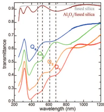
Fig. 4shows the optical transmittance spectra of the four nanocom-posite films Q1 to Q4 before immersion. The four dotted lines point on the wavelengths used by the sensor. All four spectra consist of a trans-mittance band peaking at a fixed position of 315 nm and a broad absorp-tion band covering the vis-NIR spectral domain which contains several interference fringes. The fixed transmittance band results from the min-imum of the imaginary part of the refractive index of bulk Ag kAg[23]
due to Ag interband transitions from 3.83 eV (323 nm) to higher
Fig. 3. Atomic Force Microscopy pictures of the surface of coating similar to Q4, i.e.: AgNPs embedded in a-Al2O3matrix with an Ag rich top-layer. (a) Topography signal leading to an
arithmetic roughness, Sq, of 5 nm. (b) Phase-shift mapping that highlights the contrast between AgNPs and a-Al2O3matrix.
Fig. 4. Transmittance spectra of the Q1 to Q4 coatings. Fused silica window and a-Al2O3
deposited on fused silica are shown for comparison. The four dotted lines point on the wavelengths used by the sensor.
energies[24]. The transmittance band intensity gradually increases from Q1 to Q4, due to the decrease of the film thickness, attributed to the precursor consumption and hence to a declining concentration gra-dient from the entrance to the exit of the deposition zone in the reactor. Thickness increase results in the increase of the absorption since the imaginary part of the resulting effective refractive index of the medium composed of Ag NPs (kAg≠ 0) and Al2O3(kalumina= 0) host media is non
null. Besides, the gradual displacement of the interference fringes
towards longer wavelengths is also characteristic of the film thickness increase. The absorption band originates from surface plasmon reso-nance of Ag NPs which is known to occur between 350 and 800 nm in Al2O3environments[25,26]. The transmittance at the four wavelengths
of interest for sample Q4 is between 0.5 and 0.7. This degradation of the transmittance can be reduced through appropriate tuning of the charac-teristics of the coating, namely its thickness, and the density and size of the Ag NPs, while maintaining the anti-biofouling efficiency (see next section). Since the four samples were processed in the same batch, it is expected that the size, density, and shape of Ag NPs do not
Fig. 5. XPS analysis of Q4 chemical composition (at.%) as a function of erosion time.
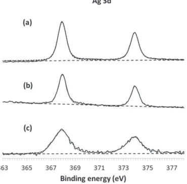
Fig. 6. Ag 3d X-ray photoelectron spectra as deposited (a), after erosion for 30 s (b) and 1030 s (c) of sample Q4.
Fig. 7. SEM surface micrograph of a bare glass window after immersion, illustrating the development of fouling. Both minerals (left and lower part of the image) and micro-organisms, namely diatoms (arrowed) are present.
significantly change in the four films. This is confirmed by the fact that the surface plasmon absorption maxima are all localized at ca. 370 nm and by the fact that the broad band seems to roughly have the same width (if one disregards the interference fringes).
Fig. 5presents the XPS depth profile of sample Q4 after immersion. The profile confirms the coating structuration targeted by the deposi-tion condideposi-tions by revealing (a) a first, ca. 3 nm external zone, (b) a main part, whose thickness is in the order of 300 nm, (c) a ca. 50 nm thick interdiffusion zone and finally (d) the glass substrate. The overall thickness for sample Q4 is estimated 350 nm by considering an erosion rate of 0.08 nm/s for a-Al2O3, to be compared with the value of 200 nm
estimated by reflectometry. This difference is attributed to uncertainties of the two methods, namely the erosion rate for XPS and the optical index for reflectometry. The thin external zone is composed of C, O, Ag and Si. Ag corresponds to the coating top-layer whereas carbon, silicon and oxygen are attributed both to the contamination of the extreme surface and to the micro-organisms which adhered on the surface dur-ing the immersion test. The main part of the coatdur-ing consists of alumi-num oxide which is homogeneous through the coating depth as the ratio of Al and O signals remains constant. The Ag signal is detected and it is close to the XPS quantification limit (0.1% at.).
The high resolution XPS signal of Ag3d is further studied to identify the oxidation state of the Ag NPs in the matrix. The Ag3d XPS spectra shown inFig. 6illustrate the bonding energies of Ag3d3/2and Ag3d5/2
on the surface (Fig. 6a) and inside the coating after 30 s (Fig. 6b) and 1030 s (Fig. 6c) of erosion. The binding energies of Ag3d3/2and Ag3d5/ 2are 374.05 eV and 368.04 eV respectively, with a splitting of the 3d
doublet that is close to 6 eV, in agreement with the literature[27]. These results confirm the TEM results, according to which the Ag in
the nanocomposite coating is in the metallic state Ag0. However, due
to the low signal-over-noise ratio, the presence of Ag(+I) at the inter-face Ag NPs/alumina cannot be excluded. Finally, the interinter-face between the coating and the glass substrate reveals the diffusion of fluorine and magnesium within the coating. Similar results are obtained for the other samples, Q1, Q2 and Q3.
Visual observation of the samples surface after immersion reveals significant differences between untreated and coated samples. The for-mer present uniform, intense development of biofouling, which covers the entire surface of the samples. The surface of the later is partly cov-ered, with large parts remaining unaffected. In both cases, the fouling consists of minerals and micro-organisms such as diatoms, as shown inFig. 7.
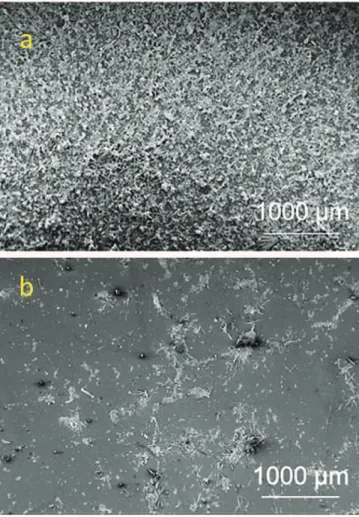
A closer observation of the samples surface was performed by SEM through surface micrographs probing a 15 mm2surface area.Fig. 8
pre-sents such two large scale micrographs, of bare (Fig. 8a) and coated (Fig. 8b) glass surfaces after immersion. The observed surfaces confirm the visual observations of the samples, namely the complete coverage by microorganisms of the surface of the untreated sample in contrast to the limited, and localized development of biofouling on the surface of the coated one.
Quantitative assessment of the biofouling fraction can be made by measuring the fraction of bright areas of SEM micrographs of four bare and four (Q1-Q4) coated samples following the procedure described in the Materials and methods section. The results of the micrographs' analysis are shown inFig. 9a where the biofouling fraction is plotted for various grayscale thresholds (0.4–0.7) used to define the bright areas. In addition to an expected decrease of measured biofouling vs. grayscale threshold, one can notice that, for all grayscale thresholds, the biofouling fraction of coated samples is systematically and unambig-uously lower than that of bare samples. To quantify this decrease, inFig. 9b we plot the ratio of biofouling of coated to the biofouling of bare sam-ples for four grayscale thresholds. The value of this ratio is included be-tween 0.30 ± 0.10 and 0.35 ± 0.17; it does not monotonically vary with the value of the grayscale threshold. It is concluded that CVD nanocom-posite thin films of Ag NPs embedded in a-Al2O3are efficient in
decreas-ing biofouldecreas-ing on glass windows.
Fig. 8. SEM surface micrographs of bare (a) and coated (b) glass samples after one week immersion.
Fig. 9. a) Bright area over total area ratios of bare and coated glass samples for a wide range of grayscale thresholds used in the analysis of SEM images, b) coated over bare bright area ratio as a function of the grayscale threefold. The error bars indicate the uncertainty of measurements in different images.
The present proof of principle paves the way to further improve-ment of the anti-biofouling efficiency by optimizing coating characteris-tics, such as the coating thickness and the Ag NPs concentration, through the fine tuning of the process conditions. The appropriate guide for this optimization would be the monitoring of the optical trans-mittance with the immersion time. Such coatings can thus be consid-ered as part of integrated tools, including for example mechanical cleaning, to reduce the maintenance of optical sensors immerged in riv-erine waters[28]. The cost of this thermally activated CVD process is limited since the deposition temperature of 723 K (450 °C) is moderate, a small quantity of AgPiv is involved and ATI, the main chemical, is inexpensive.
4. Conclusions
Nanocomposite coatings consisting of silver nanoparticles embed-ded in amorphous alumina were deposited on commercial glass win-dows aiming at the protection against biofouling of optical sensors immersed in riverine waters. The coatings were processed by an inte-grated CVD process, through codeposition of Ag from AgPiv and of a-Al2O3from ATI at 623 K and 5 Torr. The transmittance in the visible
range ranges from 0.5 to 0.7 or the thinnest, 200 nm thick films. After immersion for one week in the Saulx river, France, a threefold decrease of the percentage of the surface of these samples covered by microor-ganisms was observed, compared with the biofouling development on untreated surfaces. The critical function of biofouling delay being dem-onstrated, future perspectives of this proof of principle include correla-tion among (i) the coatings' characteristics, including thickness, roughness and Ag NPs size and concentration, (ii) the targeted function-alities, namely optical transmittance and anti-biofouling, and (iii) the durability of the functionality during the sacrificial erosion of the coat-ing. This correlation can only be investigated through longer immersion campaigns of the coated windows which should be mounted on the sensor so as to monitor the quality of the optical measurement and its evolution with time for given hydraulic, biological and environmental specifications.
Acknowledgments
This work was financially supported by ANDRA (Bure, France) under the ANDRA/053441 project grant, and by the Fondation STAE (Sciences et Technologies pour l'Aéronautique et l'Espace) (RTRA-STAE/2008/PS/ 006) project “MAISOE” (Microlaboratoires d'Analyses In Situ pour des Observatoires Environnementaux). The authors are indebted to M.C. Lafont, CIRIMAT for the TEM characterization, to J. Esvan, CIRIMAT for XPS analysis and to Ph. Behra, INPT for his continuous support. References
[1] L. Delauney, C. Compère, M. Lehaitre, Biofouling protection for marine environmen-tal sensors, Ocean Sci. 6 (2010) 503–511.
[2] A. Whelan, F. Regan, Antifouling strategies for marine and riverine sensors, J. Envi-ron. Monit. 8 (2006) 880–886.
[3] R.M. Head, J. Davenport, J.C. Thomason, The effect of depth on the accrual of marine biofilms on glass substrata deployed in the Clyde Sea, Scotland, Biofouling 20 (2004) 177–180.
[4] S. Bhatia, D. Risk, A. Pustam, T. Smith-Palmer, G. Burton, L. Melo, P. Wild, Biofouling of an all-optical sensor for seafloor monitoring of marine carbon capture and storage
sites, in: T. Dixon, H. Herzog, S. Twinning (Eds.) 12th International Conference on Greenhouse Gas Control Technologies, Ghgt-12, 2014, pp. 3848–3852.
[5] D.V. Manov, G.C. Chang, T.D. Dickey, Methods for reducing biofouling of moored op-tical sensors, J. Atmos. Ocean. Technol. 21 (2004) 958–968.
[6] L. Delauney, C. Compère, An example: biofouling protection for marine Environ-mental sensors by local chlorination, in: H.-C. Flemming, P.S. Murthy, R. Venkatesan, K. Cooksey (Eds.), Marine and Industrial Biofouling, Springer-Verlag, Berlin Heidelberg 2009, pp. 119–134.
[7] J.R. Etheridge, F. Birgand, M.R. Burchell, B.T. Smith, Addressing the fouling of in situ ultraviolet-visual spectrometers used to continuously monitor water quality in brackish tidal marsh waters, J. Environ. Qual. 42 (2013) 1896–1901.
[8] Y.X. Xue, J. Zhao, R. Qiu, J.Y. Zheng, C.G. Lin, B.J. Ma, P. Wang, In situ glass antifouling using Pt nanoparticle coating for periodic electrolysis of seawater, Appl. Surf. Sci. 357 (2015) 60–68.
[9] J.S. Patil, H. Kimoto, T. Kimoto, T. Saino, Ultraviolet radiation (UV-C): a potential tool for the control of biofouling on marine optical instruments, Biofouling 23 (2007) 215–230.
[10] Y.L. Zhang, N.Q. Zhang, Air-blast anti-fouling cleaning for aquatic optical sensors, Int. J. Agric. Biol. Eng. 8 (2015) 128–135.
[11] Q.Y. Chang, L.Z. Yan, M.X. Chen, H. He, J.H. Qu, Bactericidal mechanism of Ag/Al2O3
against Escherichia coli, Langmuir 23 (2007) 11197–11199.
[12] J.H. Kwak, J. Hu, A. Lukaski, D.H. Kim, J. Szanyi, C.H.F. Peden, Role of pentacoordinated Al3+ios in the high temperature phase transformation of
gamma-Al2O3, J. Phys. Chem. C 112 (2008) 9486–9492.
[13] A. Gleizes, C. Vahlas, M.M. Sovar, D. Samélor, M.C. Lafont, Chemical vapor deposited aluminium oxide coatings from aluminium tri-iso-propoxide: correlation between processing conditions and composition, Chem. Vap. Depos. 13 (2007) 23–29.
[14] L. Baggetto, C. Charvillat, J. Esvan, Y. Thébault, D. Samélor, H. Vergnes, B. Caussat, A. Gleizes, C. Vahlas, A process-structure investigation of aluminum oxide and oxycarbide thin films prepared by direct liquid injection chemical vapor deposition of dimethylaluminum isopropoxide (DMAI), Chem. Vap. Depos. 21 (2015) 343–351.
[15] P.-L. Etchepare, L. Baggetto, H. Vergnes, D. Samélor, D. Sadowski, B. Caussat, C. Vahlas, Direct liquid injection chemical vapor deposition of amorphous alumina from aluminum tri-isopropoxide: thin film process, structure and properties, Adv. Mater. Interfaces 3 (2016) 1600014.
[16] V. Sarou-Kanian, A.N. Gleizes, P. Florian, D. Samelor, D. Massiot, C. Vahlas, Tempera-ture-dependent 4-, 5- and 6-fold coordination of aluminum in MOCVD-grown amorphous alumina films: a very high field al-27-NMR study, J. Phys. Chem. C 117 (2013) 21965–21971.
[17] J. Mungkalasiri, L. Bedel, F. Emieux, J. Dore, F.N.R. Renaud, C. Sarantopoulos, F. Maury, CVD elaboration of nanostructured TiO2-ag thin films with efficient
antibac-terial properties, Chem. Vap. Depos. 16 (2010) 35–41.
[18]Y. Balcaen, N. Radutoiu, J. Alexis, J.D. Béguin, L. Lacroix, D. Samelor, C. Vahlas, Me-chanical and barrier properties of MOCVD processed alumina coatings on TA6V tita-nium alloy, Surf. Coat. Technol. 206 (2011) 1684–1690.
[19] A. Leyland, A. Matthews, On the significance of the H/E ratio in wear control: a nano-composite coating approach to optimised tribological behaviour, Wear 246 (2000) 1–11.
[20]M.M. Sovar, D. Samélor, A.N. Gleizes, C. Vahlas, Aluminium tri-isopropoxide: shelf life, transport properties, and decomposition kinetics for the low temperature pro-cessing of aluminium oxide-based coatings, Surf. Coat. Technol. 201 (2007) 9159–9162.
[21] L. Baggetto, C. Charvillat, Y. Thébault, J. Esvan, M.C. Lafont, E. Scheid, G.M. Veith, C. Vahlas, Amorphous alumina thin films deposited on titanium: interfacial chemistry and thermal oxidation barrier properties, Phys. Status Solidi A 213 (2016) 470–480.
[22] P. Villars, L.D. Calvert, W.B. Pearson, Pearson's Handbook of Crystallographic Data for Intermetallic Phases, Materials Park, OH, 1991.
[23] X.K. Meng, T. S.C., S. Vongehr, A review on diverse silver nanostructures, J. Mater. Sci. Technol. 26 (2010) 487–522.
[24]M. Fox, Introduction to nanophotonics, Sergey V. Gaponenko, Contemp. Phys. 52 (2011) 257.
[25] S. Camelio, E. Vandenhecke, S. Rousselet, D. Babonneau, Optimization of growth and ordering of Ag nanoparticle arrays on ripple patterned alumina surfaces for strong plasmonic coupling, Nanotechnology 25 (2014), 035706.
[26] A. Esteban-Cubillo, C. Dıaz, A. Fernandez, L.A. Dıaz, C. Pecharroman, Silver nanopar-ticles supported on α-, η-, and δ-alumina, J. Eur. Ceram. Soc. 26 (2006) 1–7.
[27] B. Ajitha, Y. Ashok Kumar Reddy, P. Sreedhara Reddy, Biosynthesis of silver nanopar-ticles using Momordica charantia leaf broth: evaluation of their innate antimicrobial and catalytic activities, J. Photochem. Photobiol. B 146 (2015) 1–9.
[28] J. Joslin, B. Polagye, Demonstration of biofouling mitigation methods for long-term deployments of optical cameras, Mar. Technol. Soc. J. 49 (2015) 88–96.