This is an author-deposited version published in: https://sam.ensam.eu Handle ID: .http://hdl.handle.net/10985/7616
To cite this version :
Rémy FABBRO Melt Pool and Keyhole Behavior Analysis for Deep Penetration Laser Welding -Journal of Physics D : Applied Physics - Vol. 43, p.445-501 - 2010
Melt Pool and Keyhole Behavior Analysis for Deep Penetration
Laser Welding
R Fabbro
Laboratoire PIMM, Arts et Metiers ParisTech, 151 Bd de l’Hopital, 75013 Paris France E-mail : remy.fabbro@gmail.com
One usually defines the main characteristic of the welding performances of a given laser system by its “penetration curve” that corresponds to the welding depth as a function of the welding speed Vw
for a given set of operating parameters. Analysis of a penetration curve is interesting and gives very fruitful results. Coupled with high speed video imaging of melt pool surface and ejected plume behaviors, the analysis of this penetration curve on a very large range of welding speeds, typically from 0 to 50 m/min, has allowed us to observe very different and characteristic regimes. These regimes are mainly characterized by the physical processes by which they impede the laser beam penetration inside the material. We show that it is only at rather high welding speeds that these limiting processes are reduced. Consequently the scaling law of welding depth with welding speed is in agreement with adapted modeling of this process. On the other hand, as the welding speed is reduced, different effects depending of the weld pool dynamics and plume interaction, strongly disturb the keyhole stability and are responsible of the deviation of the penetration curve from the previous modeling that agrees with a 1/Vw scaling law. A corresponding criterion for the occurrence
of this effect is defined.
Keywords: laser welding, keyhole, melt pool hydrodynamics, instability, penetration depths
Pacs numbers: 42.62.-b, 81.20.Vj
1. Introduction
The hydrodynamics of a melt pool generated during deep penetration laser welding has always appeared to be very complex. This melt flow is a result of the interaction of many driving forces [1]. The role of these different driving forces (such as ablation pressure, vapor plume effects, surface tension, gravity, possible induced electromagnetic forces, ...) is not totally defined, as their relative importance with the operating conditions, for example when the welding speed or incident laser intensity varies. In order to improve the understanding of these complex processes, different experiments have been performed and the evolution of melt pool dynamics for a range of welding speeds, wider than the one usually used, has been analyzed. Five typical hydrodynamic regimes can be defined by varying the welding speed from a few m/min to several tens of m/min and thus discriminate some of the driving forces. As a final result, the importance of the dynamic pressure induced by the vapor plume emitted by the keyhole front is emphasized.
In a first part of this paper, the main characteristic regimes related to the different flows observed with the variation of the welding speed, are recalled. In a second part, a dynamical model is presented. This model describing the stationary equilibrium of the keyhole front, shows how the main derived parameters (such as penetration depth, keyhole tilting angle, evaporation pressure, ...) vary with the operating parameters. Finally in the third part, these experimental results are discussed in the frame of this model. The importance of the perturbing effect of the collapse of the keyhole, due to surface tension, usually observed at low welding speeds for limiting depth penetration, is highlighted by the results.
2. Experimental results
I recall here the main experimental results, concerning the visualization of the melt dynamics observed with the high-speed video camera at a frame rate of 20 kHz, for variable welding speeds. The incident laser power and laser spot diameter are kept constant at 4 kW and 0.6 mm respectively. 304 Stainless steel samples were welded, in partial penetration. The experimental setup used as well as the main results have already been presented and detailed [2, 3]. The films analysis allows defining five main characteristic contiguous regimes, which are only controlled by the welding speed. It appears that these behaviors can be interpreted as the result of a very different action of the vapor plume on the melt pool. This action is controlled by the geometry of the keyhole front, itself defined by the welding speed and incident laser intensity.
2.1 Welding speeds below 5 m/min: "Rosenthal" regime
This regime, which is observed for welding speeds lower than 5 m/min, is characterized by a rather large melt pool, even in front of the keyhole, due to the rather low welding speed. The melt pool surface shows many chaotic surface fluctuations and large swellings of liquids fluctuating around the keyhole aperture, which is rather well defined and remains circular (see figure 1).
Because of these fluctuations, one cannot observe a clear laminar flow around the keyhole. Also, many spatters are mainly emitted from the keyhole rim, and particularly on its front side. On this range of welding speeds, one can see a rapid decrease of the penetration depth as well as large fluctuations of ejection direction of the vapor plume. These fluctuations can be correlated with the previously described melt pool swellings fluctuations. Macrographs cross sections of the weld seam show a gradual transition of the shape from the well-known "wine cup shape" characteristic of a low welding speed (typically about 1 to 3 m/min) to a more slender shape for 5 m/min. From the analysis of the keyhole tilting for these low welding speeds, which will be discussed in § 2.7, we know that the keyhole is quite vertical. Therefore, despite these fluctuations, one can schematized this regime by a vertical cylindrical keyhole surrounded by a large melt pool with very limited hydrodynamics. So the description of this situation by a kind of "Rosenthal" heat flow regime, where the keyhole surface is uniformly heated at some temperature close to the evaporation temperature, could be used.
Figure 1: Sketch of the “Rosenthal” regime. Typical view of melt pool (scale: 1mm) and cross-section (scale: 0.5 mm).
2.2 Welding speeds between 6 to 8 m/min: "Single wave" regime
This regime is observed for welding speeds ranging from 6 to 8 m/min. It is characterized by the presence of a rather large single swelling generated near the top of the rear keyhole wall (see figure 2). It is only from this region that melt droplets are emitted. This large wave is ejected rearwards quite periodically and generates back and forth oscillations of the melt pool therefore leading to quite periodic closures of the keyhole. The vapor plume is emitted rather deeply inside the keyhole and collides with the melt pool and so, triggers these oscillations. The more the welding speed is increased the more the keyhole front is tilted; as the vapor plume is emitted perpendicularly from the keyhole front surface, it is then rather directed rearwards [4]. The analysis of plume deflection variations has already confirmed this result [5].
One can observe that only the tilted keyhole front is clearly heated by the incident laser beam (contrarily to the “Rosenthal” regime where the luminosity characterizing the laser heated surface was more uniformly and randomly distributed around the keyhole surface). More interestingly, when the ejected vapor plume collides with the melt pool and lifts it, the corresponding local heating of the liquid surface as a result of the impact by this energetic heated vapor plume can be observed. So the vapor plumes not only transfers impulse momentum, but also a non-negligible amount of energy due to its rather high temperature.
Swellings Local evaporation Spatters Vapor jet
Figure 2: Sketch of the “single-wave” regime. Typical view of melt pool (scale: 1mm) and cross-section (scale:0.5 mm)
2.3 Welding speeds between 9 to 11 m/min: "Elongated keyhole" regime
This regime is observed for welding speeds ranging from 9 to 11 m/min. It is characterized by a keyhole that is elongated, with its maximum length of typically about 2 mm, observed at 11 m/min (see figure 3).
Figure 3: Sketch of the "elongated" regime. Typical view of melt pool (scale: 1mm) and cross-section (scale: 0.5mm).
However its length presents also some fluctuations, but the resulting liquid oscillations are much less intense than in the previous regime, and the height of the induced swellings is much smaller. It is interesting to note that this elongated keyhole shows two characteristic zones that are heated: the first one corresponds of course to the inclined keyhole front wall, common to all regimes, and the second one is located at the rear end of this elongated keyhole, inside the melt pool. Moreover, vapor plume seems to be also emitted from the second heated spot and so directed frontward. As in the previous regime, heating by the collision of the vapor plume emitted from the keyhole front is also possible.
Rear kehole rim Vapour impacted heated zone Melt jet Interaction zone side flow Ejected melt wave Side flow Vapour impacted
2.4 Welding speeds between 12 to 19 m/min: "Pre-humping" regime
This regime is observed for welding speeds ranging from 12 to 19 m/min. It is characterized by a rather strong melt flow that contours the keyhole front wall, whose tilting angle begins to become important. This resulting "keyhole" is then elongated (but with a shorter length than in the previous regime) and the surface of the following melt pool shows fluctuations characterized by only surface waves with rather small amplitudes.
Figure 4: Sketch of the "pre-humping" regime. Typical view of melt pool (scale: 1mm) and cross-section (scale:0.5 mm).
There is also a central melt flow that is emerging from the bottom of the very stable keyhole front wall and is deflected rearwards with its surface reaching a level close to the initial sample surface (see figure 4). The characteristic heated rear zone observed in the “elongated” regime seems very small here, only located at the bottom of the emerging flow. No more spatters or droplets are emitted, even from the rear rim of the keyhole as in the previous regime. Melt pool surface reaches the level of the surface sample and wets both sides. But above 15-16 m/min welding speeds, some undercuts are observed on the sides of the seam. In that case, one can observe that the emerging melt does not reach the sample surface near its upper sides, at the rear of this elongated keyhole. These undercuts begin to be important because the two side flows emitted from the keyhole front wall collides with the central emerging flow and press it towards its center. Finally, the vapor plume is very stable; it does not fluctuate anymore and is precisely ejected perpendicularly to the keyhole front wall.
2.5 Welding speeds above 20 m/min: "Humping" regime
For our operating conditions, above 20 m/min, we reach the very characteristic humping regime that can be defined by the occurrence of a weld seam with very strong undercuts, composed of solidified large swellings of quite ellipsoidal shape, separated by smaller valleys.
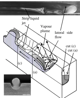
The melt flow that is coming from the keyhole region presents very particular characteristics [3]. As in the previous regime, the main central flow is always emerging from the bottom of the keyhole front wall (see Figure 5); it is strongly deflected rearwards and it rises up to a level that is much lower than the surface sample. It stays attached to the sidewalls along a distance of about 2 mm and then a liquid jet from the central part of this flow is detached and forms a thin vertical strip that propagates rearwards at high velocity. It is along this strip of liquid jet that the humps appear at a certain distance from the detachment point [3]. In fact, a shrinkage of this melt jet strip, due to the Rayleigh instability driven by surface tension, can be observed at a certain distance, typically 2 mm from the detachment point. This shrinkage cools locally this strip of melt jet and so attaches it to the sample. The fluid flowing inside this strip of melt jet is then stopped at this point, and a hump can grow. lateral side flow interaction zone Undercut Emerging flow
Figure 5: Sketch of the "humping" regime, with corresponding cross sections of melt flow at two positions (a) and (c).
Typical view of melt pool (scale: 1mm) and cross-section of a hump (scale: 0.5 mm).
The growth of this hump is stopped when a new shrinkage occurs at the same distance from the detachment point which induces the growth of a new hump. Of course, as this thin melt jet strip is located at the center of section of the groove, very severe undercuts are generated even near the humps. For higher welding speeds this scheme is not modified.
Figure 6: Location of the 5 previously described regimes respectively labeled R, S, E, P, H, in the incident laser power -
welding speed plane. Locations of keyhole (K) and conduction (C) regimes are also indicated. Linear best fits for the R/S, S/E and E/P transitions, with corresponding keyhole front wall tilting angle. The focal spot diameter used here is 0.45 mm. The 5 previous regimes have been observed for a given set of operating parameters, namely an incident laser power of 4 kW and a focal spot of 0.6 mm. In order to analyze the behavior of these regimes with other parameters, these experiments have been reproduced by using incident laser powers varying between 2.5 and 4 kW. Also, in order to have a greater range of incident intensities, the focal spot was reduced to 0.45 mm. The same regimes were of course observed but with modified welding speeds thresholds. These results are reported on figure 6. On that figure we have delimited the regions where the welding is realized with a keyhole regime (labeled K), and where only conduction regime is observed (labeled C). Typically, for a welding speed of 25 m/min, keyhole regime is obtained for incident laser power greater than 0.5 kW. Of course, this power increases with the welding speed.
For incident power varying from 2.5 to 4 kW, we have reported the welding speeds thresholds between the Rosenthal / Single-wave / Elongated / Pre-humping / Humping regimes (the 5 corresponding regimes are labeled respectively R, S, E, P, H). Except for the P/H transition, all the others characteristic thresholds increase with the incident laser power. One can see
lateral side flow Strip liquid jet Vapour plume (a) (c) cut (c) cut (a)
that best-fit lines passing through the origin can be plotted through these 3 series of experimental points of these consecutive regimes.
For the P/H transition, it is interesting to note that for incident laser powers smaller than 2.5 kW, no humping instability is observed, even at very high welding speed. Also, when the incident power increases, the P/H welding speed threshold decreases; this behavior is similar to previous experimental results but obtained for different conditions [6]. The very different behavior of this P/H transition compared to the 3 previous one, results probably from the very different mechanisms driving this humping instability. It is also interesting to notice that if we extrapolate the P/H transition at higher incident powers, the pre-humping region should disappear. This behavior could be verified by using higher laser powers, for example with new fiber or discs lasers.
2.6 Penetration depths scaling
Figure 7 shows the variation of the corresponding penetration depth e as a function of the welding speed. Despite the various phenomena described above, this curve appears quite continuous. The 1/e variation has also been reported and one can observe that above a certain welding speed, around 6-8 m/min, this scaling is quite linear. It is interesting to note that this behavior occurs for regimes where the keyhole remains opened and beam incidence on front keyhole wall is not disturbed by the fluctuating keyhole closures (so corresponding to “elongated” regimes).
Figure 7: Penetration depth e and 1/e variations as a function of the welding speed. Incident laser power: 4 kW; Focal spot
diameter: 0.6 mm; Material: 304-stainless steel.
In fact, this is a general result that can be observed for any set of operating parameters: above a critical welding speed Vwc,
the penetration curve always scales as the 1/Vw. For welding speeds lower than Vwc, of course the penetration depths still
increases, but with a smaller rate that 1/Vw, and even saturates for static conditions (Vw = 0).
Moreover, one can also observe from many results reported by different laboratories that this critical welding speed Vwc is a
decreasing function of the focal spot diameter, i. e. as the focal spot increases, the 1/Vw scaling remains valid for smaller
welding speeds.
An example of this behavior is shown on figure 8, where penetration curves obtained for very different focal spot diameters have been plotted [7, 8]. The range on which the 1/Vw scaling is observed is more extended for large focal spots. Similar
behaviors on the effect of spot size have been observed in several publications [9, 10, 11].
Figure 8: Penetration depths as a function of welding speed for 4 different focal spot diameters:
- 125 and 200 microns, (from ref. [7], 4 kW, Nd-Yag laser) - 600 and 1000 microns, (from ref. [8], 4 and 6.3 kW, diode laser)
2.7 Keyhole front tilting angle
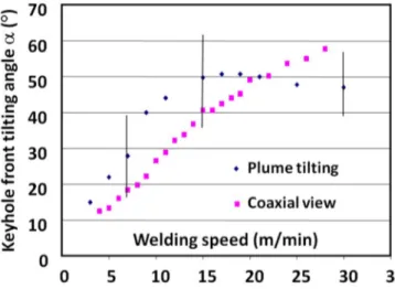
The tilting angle of the keyhole front is also another experimental data that plays an important role in the keyhole dynamics. Its value has been reported on Figure 9 as a function of the welding speed, for a 4 kW incident power and 0.6 mm focal spot diameter. Two methods have been used for its determination [17]: one uses the measurement of the maximum plume deflection observed on a video sequence (assuming that the vapor plume is emitted perpendicularly from the keyhole front), the other one uses measurements of the longitudinal front keyhole extension through coaxial view during full penetration experiments. These results show that the KH front angle scales quite linearly with the welding speed. Very similar behaviors and scaling, but resulting from the measurement of spatters ejection angle, have been obtained by Weberpals et al. [10].
Figure 9: Keyhole front tilting angle as a function of welding speed for two different methods of observation. 3. Dynamical model of keyhole.
3.1 Basic modeling
The previous experimental results have been analyzed in the frame of our dynamical model of keyhole front equilibrium [12, 13]. This scheme is based on the local equilibrium of the keyhole front wall under the two opposite effects that tend to displace it, which are the welding speed Vw and the drilling velocity Vd that results of the penetration of the laser beam
inside material. For a uniform incident intensity profile, a scheme of the longitudinal section of the front and rear keyhole walls with corresponding notations is shown on figure 10.
Figure 10: Scheme of the longitudinal section of a keyhole in a case of full penetration. Incident beam has a uniform
intensity I0, with a diameter D. Material is moving from left to right with the welding speed Vw.
The keyhole front wall is tilted with an angle relatively to the vertical laser beam. The kinematic condition of equilibrium of the keyhole front, which states that there is no displacement along its normal, means that the projection along the normal to the keyhole front wall of the welding speed Vw has to be equal to the "drilling" velocity Vd that results of the penetration
of the laser beam inside material (this drilling velocity is always normal to the local surface). This allows us to write the basic equation of equilibrium for stationary conditions [12, 13]:
Vd = Vw . cos (1)
We will now consider the well-known “piston model” [14, 4] and make the assumption that the resulting drilling velocity Vd, is proportional to the local absorbed laser intensity. This is a very convenient approximation that can be checked in a
Vd = k Iabs = k I0 A() sin (2)
where I0 is the incident laser intensity, A() the local absorptivity and sin, the cosine of the local angle of incidence of the
laser beam. The parameter k (≈ 3 10-11 m3/J, for our experimental conditions, on 304-stainless steel), is the proportionality factor that can be also determined experimentally for similar conditions of incident laser intensity [4]. One can determine that k mainly depends on the thermal properties of the used material. The absorptivity A() depends of the angle of incidence and one can use a Fresnel-like equation for A() [14]:
A() = A0 (sin)q (3)
where A0 is the absorptivity under normal incidence and q has a rather small value (q ≈ 0.1).By combining equations 1 to 3,
in the limit of small values of q and for low welding speed Vw, one obtains the variation of angle with operating
parameters:
≈ Vw
/
(k I0 A0) (4)It is interesting to note that this scaling of is in agreement with our previous results for the welding speed variation. Weberpals et al. [10] have also observed a similar scaling with the incident intensity I0.
For defining the maximum penetration depth e, one can consider that this depth is obtained when the incident beam is entirely intercepted by the keyhole front, i. e. when the relation:
tan ≈ D/e (5)
is fulfilled.
In fact this relation would be exact if the absorptivity A0 was very large. Typically, for these conditions, we have shown that
A0 ≈ 0.7 (on stainless steel). So, one can expect some multireflections. By taking into account these multireflections, one
can show that for these conditions of incident intensity, 1 to 2 more reflections occur, and the maximum keyhole depth is increased by about 30%. Nevertheless, we will use equation 5 for closing the problem and combined it with equations 1 and 2. One can therefore determine this penetration depth that is given by:
(6)
where P is the incident laser power (for deriving (6), we have only considered that q ≈ 0).
Again, the equation 6 shows that the penetration depth scales as 1/Vw, as previously observed experimentally for high
welding speeds. It also shows a 1/D scaling (where D is the spot diameter): it is important to note that this scaling has also been observed experimentally, but only when these focal spots are rather large [9-11]. For small focal spots, the penetration depth appears to be quite constant with the spot diameter. An attempt of explanation of this behaviour will be discussed in the next paragraph.
By using this model one can also determine the absorbed intensity Iabs on the keyhole front, which is given by: Iabs = I0 A0
sin (for the sake of simplicity, we will also consider here that q ≈ 0). In the limit of low values of , it is easy to see that Iabs is given by:
Iabs = I0 A0 sin = Vw/k (7)
Equation 7 is interesting because it shows that for low angles (obtained for low welding speeds and/or for high incident intensity), the absorbed intensity on the keyhole front is totally independent of the incident intensity (or focal spot diameter); it only depends of the welding speed. This is a self-regulating mechanism: for a given welding speed, when the incident laser intensity increases, the keyhole front tilting angle decreases (equation 4), correspondingly the penetration depth also increases (equation 6), but the absorbed intensity on the keyhole front (equation 7) remains constant! Of course, when the welding speed increases or the incident laser intensity decreases, the angle increases and the absorbed intensity also increases and tends to the limit I0 A0. We will see the importance of this behavior in the next paragraph.
3.2 Discussion
3.2.1. Regime transition thresholds. From our previous analysis of the keyhole front equilibrium, one can relate the slope of the 3 best-fit lines plotted on Figure 6 through the experimental thresholds of the corresponding transitions, with the mean tilting of the keyhole front. It is easy to verify that in a (P - Vw) diagram, a linear relation occurs between incident laser
power P and welding speed Vw:
w 0 DV P kA 4 e
P = B . Vw, (8)
Where by using equations 5 and 6, the slope B of this linear relation between P and Vw, is given by:
B =
=
(9)
From equation 9, the angle that reproduces the slopes of these 3 best-fit lines drawn on Figure 6 are 15°, 30° and 45° for respectively the R/S, S/E and E/P transitions. One can note that these angles are in fair agreement with the experimental observations that can be obtained by using the high speed videos.
Moreover, our model also shows that this slope B is proportional to the penetration depth (equation 9). Therefore, for a given transition (R/S, or S/E, or E/P) all the welding speed thresholds corresponding to that transition occur at the same penetration depth or angle . Of course as expected, when one goes from R to P regimes, the corresponding penetration depths decrease as the welding speeds increase.
So these results would indicate that the transition between these first 4 regimes is basically controlled by a characteristic tilting angle of the keyhole front wall. As we know that this angle also defines the direction and the dynamic pressure of the emitted vapor plume (this vapor plume being directed perpendicularly to its emitting surface), these results confirm that it is the level of interaction of the vapor plume with the rear melt pool that defines the type of its hydrodynamic regime [2]. At low welding speeds, the keyhole front wall is slightly tilted; the absorbed intensity is then rather small, as well as the dynamic pressure of vapor. The vapor plume is directed quite horizontally inside the melt pool and so perturbs the melt pool from its bottom. This would correspond to the occurrence of the Single wave regime. As the welding speed increases, the tilting angle increases, as well as the absorbed intensity and correspondingly the dynamic pressure of the vapor plume. But this vapor plume is more likely emitted quite vertically and therefore perturbs more efficiently the top part of the melt pool as in the Pre-humping regime.
3.2.2. Penetration curve analysis. We have seen that at low welding speeds, the experiments show that the penetration curve strongly deviates from the 1/Vw scaling and even saturates at very low welding speeds. A perturbing mechanism is probably
responsible of this limitation. Our video movies show that for these conditions (“Rosenthal” regime), strong keyhole fluctuations are observed and one cannot anymore consider a stationary regime in these conditions.
Equation 7 shows that at low welding speed, the absorbed intensity on the keyhole front, which is only a function of this welding speed, is rather low for these conditions. On the other hand, we know that the evaporation pressure resulting of the absorbed intensity is a direct function of this absorbed intensity. In previous experiments, by using a deflection technique [15], we have estimated this evaporation pressure Pevap that can be given by the following relation:
Pevap ≈ C Iabs (10)
where C ≈ 6 10-6 s m-1(for 304-stainless steel). The constant C is also strongly dependent on the thermal properties of the used material.
It is this evaporation pressure that maintains opened the keyhole: the metallic vapor generated by the evaporation process from the keyhole front wall impinges the rear keyhole wall and impedes its collapse. Of course, this effect is only possible if this evaporation pressure is greater than the closing pressure P, resulting from the local surface tension, which is defined by
the relation:
P = 2/D (11)
where is the surface tension of the melt pool liquid.
Therefore, by using equations 7, 10 and 11, the condition Pevap > P for maintaining an opened keyhole for these conditions
of low welding speeds becomes:
(C/k) Vw >2/D (12)
Typically, for ≈1.5N/m, the equation 12 shows that the welding speed must be greater than 1.8 m/min in order to maintain opened a 0.5 mm keyhole diameter. These low values of welding speed agree fairly well with those observed for different experiments. The scaling obtained with the equation 12 is also in agreement with the previously described results that indicate a greater range of welding speeds for disturbed penetrations depths when smaller focal spots diameters are used. In fact for this regime, the keyhole cannot be stationary; after its internal collapse, it is continuously re-opened by the continuous incoming incident laser beam. As equation 12 defines a maximum value for the product D.Vw (> 2k/C), from
equation 6, one can finally determine the corresponding maximum penetration depth emax given by (13):
emax ≈
Equation 13 gives the maximum penetration depth for achieving a stable keyhole regime; above emax, as explained
previously, one can expect strong fluctuations that may lead for example to some defects such as porosity of the weld seam and correspondingly some reduction of the penetration depth. One can note that this maximum depth is only dependent of the incident laser power P. As a conclusion, for achieving a given deep penetration, this analysis shows the interest of using high power laser with the largest focal spot diameter compatible with the required welding speed. Using the previously defined parameters, equations 13 and 12 can be expressed in practical units as follows (for 304 stainless steel):
emax(mm) ≈ 1.5 P(kW) and Vw(m/min) . D(mm) > 1 (14)
3.2.3. Effect of a side gas jet. In the previous paragraph we have seen that for low welding speeds, the evaporation pressure is not enough intense for maintaining an opened keyhole, in stationary conditions. A possible method for helping this opening consists in using a side gas jet that delivers a neutral gas inside the keyhole [16, 17] (see figure 11). If the gas is correctly delivered, the dynamical pressure of the gas jet can be adjusted in order to balance the closing pressure due to surface tension effects.
Figure 11: Scheme of the positioning of the gas jet used for opening the keyhole during welding. Each configuration of
rear or front jet can be used, they both give very similar results.
Typically a flow rate of 20 l/min of Argon gas, delivered through a 2 mm diameter nozzle, generates on the nozzle axis a dynamical pressure of 20 kPa, at 5 mm from the keyhole aperture. By adjusting the Argon flow rate, one can therefore generate any dynamical pressure inside the keyhole.
Figure 12 (a) and (b) show characteristic images extracted from a video sequence of two experiments: one experiment (a) is obtained without the use of the gas jet and the other (b) is obtained when the gas jet delivers a dynamical pressure of 8 kPa inside the keyhole. When the gas jet is properly used, the hydrodynamic flow of the melt pool is completely controlled: it is ejected rearwards in a continuous, stationary and quite laminar flow that is completely different from what is observed without the gas jet; we have shown in § 2.1 that in that case, this corresponds to the previous “Rosenthal regime”, where the flow is chaotic and non-stationary with many bumps generated around the keyhole rim. Moreover, the penetration depth obtained with the gas jet is about 40% greater than without the gas jet, and porosities have disappeared [17].
So, we consider that this experiment confirms the previous given scheme that for these low welding speeds, the internal pressure inside the keyhole, generated by the ejected metallic vapor from the keyhole front, is not large enough for counterbalancing the closing pressure of the keyhole due to surface tension effects. In these conditions, a stationary keyhole can no longer exist; this keyhole must be “re-drilled” quite periodically and therefore the corresponding keyhole depth is limited compared to a situation where the keyhole has enough time to be fully developed.
Figure 12: Images extracted from a video sequence obtained without (a) and with (b) an optimized side gas jet.
Welding speed: 3 m/min. Plaser: 3 kW. White vertical arrows show the axis of incident laser beam location.
(a)
In fact one could consider that this behavior could be also an initiating phenomenon for producing “humps” that generate disturbances of the keyhole front. The local collapse of the keyhole walls generates a “normal” surface to the incident beam, which is then pushed downwards very efficiently due to the very high resulting local intensity, as in the drilling phenomena,. But the welding displacement makes a perturbation of this drilling process that stops it and induces a small angle of the keyhole front from which the local absorbed intensity decreases. This generates the following cycle: decreased evaporation pressure, followed by local collapses of the keyhole, and the process is then repeated.
4. Conclusion.
Coupled to previous experimental results where the geometry of the keyhole front [4], and the dynamic pressure of ejected vapor plume [5], have been analyzed, for various conditions, the analysis of induced flow inside melt pool has led us to conclude that the interaction of this vapor plume with the melt pool generates or modifies its hydrodynamics, which was initially defined by the side flows of the melt generated underneath the focal spot by the local “piston effect” [14]. The tilting of the keyhole front wall and the corresponding dynamic pressure of the ejected vapor plume control the degree of coupling between the vapor plume and the melt pool, which finally defines the induced regime: Friction stresses induced by the vapor flowing along the walls of a quite vertical keyhole in case of low welding speeds [2], or direct collision of the vapor with the keyhole rear wall, generate strong waves and perturbations in the melt pool at higher welding speeds. Above a critical welding speed, the liquid jet rearwards accelerated by the evaporation pressure generates the humping instabilities. The previous experiments have been performed with a rather large focal spot (0.6 or 0.45 mm) compared to those achievable with recent high beam quality lasers, which are thus able to deliver intensities more than one order of magnitude greater. The importance of the keyhole front wall tilting in the appearance of the different regimes has been highlighted. Whereas this parameter is a monotonic function of the ratio Vw/I0 (I0: incident laser intensity, see equation 4), similar
characteristic regimes with these high beam quality lasers should also be observed, but they should appear at much higher welding speed thresholds. Some experiments with high beam quality lasers have already shown that critical welding speeds for "melt flow dynamic" humping process was largely increased [18, 19]. So, future corresponding detailed experiments will be welcomed for confirming the occurrence of these regimes in these extreme conditions.
In a second part of this article, we have analyzed the penetration depth curve. It has been shown that at high welding speeds the scaling of 1/Vw, in agreement with our dynamical model of keyhole front equilibrium, is generally observed, and that the
focal spot diameter is the main parameter that controls the range of this 1/Vw scaling: the greater the focal spot diameter, the
larger extent of this velocity range. At low welding speed, our dynamical model predicts that the absorbed intensity on the keyhole front is independent of incident intensity and only depends of the welding speed. As this absorbed intensity defines the resulting evaporation pressure, which is therefore decreased for these conditions, the collapse of the keyhole can occur at low welding speed and this effect limits the penetration depth of the keyhole that becomes non-stationary. This result is important because it shows the limited interest of small focal spots when large penetration depths are required. In fact, we show that it is the available incident laser power that defines the maximum stable penetration depth. The recent advent of lasers delivering output powers above about 10 kW, should allow the achievement of correct weld seams of about 10 to 15 mm in depth, at interesting welding speeds and with adapted focal spot diameters. Finally, a side gas jet of Ar gas, with a correctly adjusted induced dynamical pressure, allows to keep open the keyhole, with an increased penetration depth for these low welding speeds.
These experiments have therefore emphasized the importance and the complexity of the hydrodynamics of the melt pool during laser welding. It is clear that if one wants a correct description of the melt pool and beyond it, the final weld seam geometry, particularly at high welding speeds, it is necessary to master 3-D simulations dealing with free surface problems. Moreover, if one wants to take into account the complete process of vapor effect during the laser welding process, it is also necessary to describe the vapor-free surface interaction, which is presently a very complex issue for numerical simulations, which has been addressed up to now in very few publications [20, 21].
References
[1] Matsunawa A 2001 Understanding physical mechanism in laser welding for mathematical modeling and process monitoring, Proceedings of the LIM'2001 Conference, Munich, Germany, 79-93
[2] Fabbro R, Slimani S, Coste F, Briand F 2007 Analysis of the various melt pool hydrodynamic regimes observed during CW Nd-Yag deep penetration laser welding, in Proceedings of the ICALEO'2007 Conf., Orlando, USA, 382-390 [3] Fabbro R, Slimani S, Coste F, Briand F 2007 Experimental study of the humping process during Nd:Yag CW laser
welding, Proceedings of the LIM Conf, Munich, Germany, June 18-21
[4] Fabbro R, Slimani S, Coste F, Briand F 2005 Study of keyhole behavior for full penetration Nd-Yag CW laser welding, J. Phys. D: Appl. Phys. 38, 1881-1887
[5] Fabbro R, Slimani S, Doudet I, Coste F, Briand F 2006 Experimental study of the dynamical coupling between the induced vapor plume and the melt pool for Nd-Yag laser welding, J. Phys. D: App. Phys. 39, (2006) 394-400
[6] Thomy C, Seefeld T, Wagner F, Vollertsen F 2006 Humping in welding with single mode fiber lasers, in Proceedings of the ICALEO'2006 Conference, Scottsdale, USA, Oct. 30 - Nov. 2, 543-552
[7] Beyer E 2008 High power laser materials processing – New developments and trends, Proceedings of the 3rd PICALO’2008 Conference, Beijing, China, 5-9
[8] Luft 2009 A New applications for welding with diode lasers, Proceedings of the 5th International WLT-Conference on Lasers in Manufacturing 2009 Munich, June 2009
[9] Verhaeghe G, Hilton P 2005 The effect of spot size and beam quality on welding performance when using high-power continuous wave solid-state lasers, Proceedings of the ICALEO’2005 Conference, Miami FL, USA, 264-271
[10] Weberpals J, Dausinger F 2008 Fundamental understanding of spatter behavior at laser welding of steel, Proceedings of the ICALEO’2008 Conference, Temecula CA, USA, 364
[11] Suder W, Williams S, Colegrove P 2009 Absolute spot size effect on penetration depth in laser welding, Proceeding of the 5th International WLT-Conference on Lasers in Manufacturing 2009 Munich, June 2009, 53-58
[12) Fabbro R, Chouf K 2000 Keyhole modelling during laser welding, J. Appl. Phys. 87(9), p. 4075-4083
[13] Fabbro R, Chouf K 2000 Dynamical description of the keyhole in deep penetration laser welding, J. Laser Appl. 12(4), 142-148
[14] Semak V, Matsunawa A 1997 The role of recoil pressure in energy balance during material processing, J. Phys. D: Appl. Phys., 30, 2541-2552
[15] Fabbro R, Slimani S, Coste F, Briand F, Dlubak B and Loisel G 2006 Analysis of basic processes inside the keyhole during deep penetration Nd-yag CW laser, Proceedings of the ICALEO’2006 Conference, Scottsdale AZ, USA, 1-7 [16] Kamikuki K, Inoue T, Yasuda K, Muro M, Nakabayashi T and Matsunawa A 2002 Prevention of welding defect by
side gas flow and its monitoring method in continuous wave Nd:Yag laser welding, J. Laser Appl. 14(3), 136 - 145 [17] Fabbro R, Slimani S, Doudet I, Coste F, Briand F 2005 Importance of the Coupling Between the Induced Vapor Plume
and the Melt Pool, for Nd-Yag CW Laser Welding, Proceedings of the ICALEO’2005 Conference, Miami FL, USA, 1075-1081
[18] Behler K, Schäfer P 2005 Melt pool dynamics in high speed welding with modern high power solid state lasers, in Proceedings of the ICALEO'2005 Conference, Miami, USA, Oct. 31 - Nov. 3, 1026-1031
[19] Myamoto I, Park S, Ooie T 2004 High-speed microwelding by single-mode fiber laser, Proceedings of the 4th LANE'2004 Conf., Erlangen, Germany, 55-66
[20] Ki H, Mohanty P S, Mazumder J, 2002 Modeling of Laser Keyhole Welding: Part I. Mathematical Modeling, Numerical Methodology, Role of Recoil Pressure, Multiple Reflections, and Free Surface Evolution, Metallurgical and Materials Transactions A, 33A, 1817-1830
[21] Amara E H, Fabbro R, Hamadi F 2006 Modeling of the melted bath movement induced by the vapor flow in deep penetration laser welding J. Laser Appl. 18(1), 2-11