HAL Id: hal-01068090
https://hal.archives-ouvertes.fr/hal-01068090
Submitted on 24 Sep 2014
HAL is a multi-disciplinary open access
archive for the deposit and dissemination of
sci-entific research documents, whether they are
pub-lished or not. The documents may come from
teaching and research institutions in France or
abroad, or from public or private research centers.
L’archive ouverte pluridisciplinaire HAL, est
destinée au dépôt et à la diffusion de documents
scientifiques de niveau recherche, publiés ou non,
émanant des établissements d’enseignement et de
recherche français ou étrangers, des laboratoires
publics ou privés.
Degradation modes and tool wear mechanisms in finish
and rough machining of Ti17 Titanium alloy under
high-pressure water jet assistance
Yessine Ayed, Guénaël Germain, Amine Ammar, Benoit Furet
To cite this version:
Yessine Ayed, Guénaël Germain, Amine Ammar, Benoit Furet. Degradation modes and tool wear
mechanisms in finish and rough machining of Ti17 Titanium alloy under high-pressure water jet
assistance. Wear, Elsevier, 2013, 305 (1-2), pp.228-237. �10.1016/j.wear.2013.06.018�. �hal-01068090�
Science Arts & Métiers (SAM)
is an open access repository that collects the work of Arts et Métiers ParisTech
researchers and makes it freely available over the web where possible.
This is an author-deposited version published in:
http://sam.ensam.eu
Handle ID: .
http://hdl.handle.net/10985/8608
To cite this version :
Yessine AYED, Guénaël GERMAIN, Amine AMMAR, Benoit FURET - Degradation modes and
tool wear mechanisms in finish and rough machining of Ti17 Titanium alloy under high-pressure
water jet assistance - Wear - Vol. 305, n°1-2, p.228-237 - 2013
Any correspondence concerning this service should be sent to the repository
Administrator :
archiveouverte@ensam.eu
Degradation modes and tool wear mechanisms in finish and rough
machining of Ti17 Titanium alloy under high-pressure water
jet assistance
Y. Ayed
a,n, G. Germain
a, A. Ammar
a, B. Furet
baArts et Métiers ParisTech, LAMPA, 2 bd du Ronceray, 49035 Angers Cedex, France
bIUT Nantes, IRCCyN, 2 av. du Professeur Jean Rouxel 44475 Carqefou, France
a r t i c l e
i n f o
Article history: Received 8 March 2013 Received in revised form 28 May 2013
Accepted 13 June 2013 Available online 26 June 2013 Keywords:
Water jet assisted machining Tool wear mechanisms EDS analysis Surface roughness Tool life Titanium alloy
a b s t r a c t
This article presents the results of an experimental study on the Ti17 titanium alloy, which was carried out to analyze tool wear and the degradation mechanisms of an uncoated tungsten carbide tool insert. Two machining conditions, roughing and finishing, have been studied under different lubrication conditions. The experimental procedure included measurement of the cutting forces and the surface roughness. Different techniques have been used to explain the tool wear mechanisms. Distribution maps of the elemental composition of the titanium alloy and the tool inserts have been created using Energy Dispersive X-ray Spectroscopy (EDS). An area of material deposition on the tool rake face, characterized by a high titanium concentration has been observed. The width of this area and the concentration of titanium, decrease when increasing water jet pressure. The study shows that wear mechanisms, with and without high-pressure water jet assistance (HPWJA) are not the same. For example, for the roughing condition using conventional lubrication, the temperature in the cutting area becomes very high, this causes plastic deformation of the cutting edge which results in its rapid collapse. By contrast, this problem disappears when machining with HPWJA. In addition, the evolution of flank wear (VB) is stabilized with high-pressure lubrication. In this case, the most critical degradation mode is due to notch wear (VBn) leading to the sudden rupture of the cutting edge.
&2013 Elsevier B.V. All rights reserved.
1. Introduction
Titanium alloys are known for their excellent mechanical properties, even at elevated temperatures, but this leads to high cutting forces and a significant release of heat that results in rapid wear of the cutting tool. This problem requires the use of low cutting speeds to mitigate wear evolution. In order to increase productivity, recent research has focused on several areas. One of these is the development of different types of machining assis-tance. In this study, high-pressure water jet assisted machining of the Ti17 titanium alloy is investigated. This assistance consists of projecting a water jet at high-pressure between the tool rake face and the chip. The efficiency of the process depends on the choice of the machining operating parameters of as well as those of water jet, such as its pressure and its diameter. The use of this assistance considerably improves tool life and chip breaking. In conventional machining, many studies have focused on tool wear, especially in terms of the machining of titanium alloys and nickel-based alloys.
According to the study done by Hartung et al.[1]tungsten carbide WC is one of the best materials for machining titanium alloys. This is due to the formation of a stable titanium layer between the tool rake face and the chip that protects against crater wear. The work of Venugopal et al. [2,3] and Wanigarathne et al.[4] also shows that uncoated carbide WC/Co is among the best solutions for machining titanium alloys. The most important wear mechanisms in this case are adhesion, diffusion and plastic deformation of the cutting edge. Studies on tool wear under HPWJA show a significant increase in tool life. Indeed, Machado et al.[5]found an increase of about 300% in tool life when machining the Ti-6Al-4 V titanium alloy. Ezugwu and Bonney[6]noted an increase of 460%, and 740%, respectively, when machining Ti-6Al-4 V and inconel718. Bouchnak [7] registered an increase of 185% when machining the Ti555-3 alloy.
Cutting tool wear is due to many phenomena that are activated, in particular, depending on the temperature obtained in the cutting zone. Childs et al. [8] explained the origins of wear mechanisms as a function of the temperature and organized them into three categories:
!
Mechanical origin: abrasion, fatigue, rupture and erosion.!
Thermal origin: plastic deformation, diffusion and chemical reactions (oxidation).0043-1648/$ - see front matter & 2013 Elsevier B.V. All rights reserved. http://dx.doi.org/10.1016/j.wear.2013.06.018
n
Corresponding author. Tel.: +33 613018828; fax: +33 241207320.
!
Adhesion: bonding and/or welding of material on the rake face.The Ti17 alloy is one of the most difficult-to-machine titanium alloys. However, most of the published research on this material focuses on its fatigue and mechanical behavior. This paper pre-sents a contribution to the understanding of the wear mechanisms and degradation modes of an uncoated carbide tool under high-pressure water jet assistance, using different techniques to follow tool wear.
2. Experimental setup
Tests were carried out to highlight the wear mechanisms and their evolution in conventional machining (without assistance) as well as under high-pressure water jet assistance. The machine used for these tests is a LEADAWELL LTC25iL lathe with a maximum power of 24 kW. Force measurement is done using a Kistler 9257B dynamometer which allows the acquisition of the three cutting force components. In order to inspect tool wear, a binocular microscope and a scanning electron microscope (SEM) were used.Fig. 1shows the types of wear.
Two machining conditions (roughing and finishing) and three lubrication modes were tested (conventional lubrication and high-pressure lubrication (100 bars and 250 bars)). The cutting para-meters are VC¼ 50 m/min, a p¼3 mm, f ¼0.3 mm/rev for the roughing condition, and VC¼50 m/min, a p¼1.5 mm, f ¼0.1 mm/ rev for the finishing condition. An uncoated tungsten carbide WC/Co (H13A) tool insert was used in this study (Sandvik reference CNMG 120412 23).Table 1shows the geometrical characteristics of the tool. For each test, the evolution of the following parameters is recorded to determine the wear mechanisms:
!
Flank wear (VB).!
Qualitative observation of crater wear.!
Surface roughness (Raet Rz).!
Cutting forces (Fc, Fr, Fa).!
Deposits on the tool material by the EDS technique.Each surface roughness measurement was repeated three times, so the total number of the values found is about 300. The values presented in this study are the average values (about 100). The same number of tests was done for the measurement of flank wear.
3. Finishing tests
Fig. 2 shows the morphology of the chips obtained when machining with conventional lubrication and with HPWJA at 100 bars, respectively. It can be seen that HPWJA ensures chip fragmentation.
Fig. 3(a) shows the evolution of the flank wear criterion (VB) and (b) the evolution of the Racriterion. For all the configurations, flank wear (VB) does not exceed 0.15 mm after 20 min of machin-ing, but its evolution is slower with HPWJA. Indeed, in conven-tional lubrication after the running-in phase, flank wear increases linearly to 0.15 mm after 20 min.
However, for the HPWJA condition, after the running-in phase, the flank wear remains constant for a significant period. Indeed, in both assistance configurations (100 bars and 250 bars), flank wear remains constant at about 0.08 mm for approximately 6 min at a pressure of 100 bars and for about 9 min at a pressure of 250 bars. After this stable regime, flank wear increases in a way similar to conventional lubrication.Fig. 3(b) shows a significant variation of surface roughness. For conventional lubrication, the surface rough-ness tends to increase linearly as a function of machining time, going from Ra¼ 0:25 μm to Ra¼ 0:7 μm (i.e. Rareaches three times its initial value). For tests with high-pressure water jet assistance, the initial surface roughness is higher, but its value remains globally constant (between 0:4 μm and 0:6 μm throughout the test). In addition, there is no marked tendency for the surface roughness to increase even at the end of the test. The surface roughness thus appears uninfluenced by flank wear.
After visual observation of the machined surface, the existence of scratches caused by the projection of the chips under the action of the lubricant jet was noticed. In fact, under the action of the high-pressure water jet, the chips are fragmented (with a length of about 3 mm) and are projected at high velocity onto the machined
Fig. 1. Types of wear[9].
Table 1
Geometrical characteristics of the tool.
Geometrical parameters Values
Nose radius rϵðmmÞ 1.2
Edge radius rβðμmÞ 30
Rake angle (deg) 7
Flank angle (deg) 6
Cutting edge inclination angle (deg) −6
surface. These scratches are more noticeable with increasing water jet pressure.
Figs. 4–6show the SEM images of the worn areas on the tool rake face and on the tool flank face for the three tests in the finishing condition. For conventional lubrication, significant flank wear at the nose radius (VBc) is observed. In addition, layers adhering to the rake face are noticed. During machining, the chip rubs on these adherent layers which appear to protect the rake face. However, when the formation of these layers reaches a stagnation level, they become instable and may be peeled-off
leading to wear by adhesion[10]. Alternatively, with HPWJA, a loss of material on the tool rake face and the formation of a crater can be seen. Damage in these areas is more important at a pressure of 250 bars. In this case, it seems that the most important wear mechanism is adhesion accompanied by abrasion and erosion.
During machining, material deposits are created between the chip and the tool. The high contact pressure and the high cutting temperature cause the welding of these deposits to the tool rake face[11]. With HPWJA, parts of the adherent layers are removed under the action of the water jet. When the deposits are detached
Fig. 2. Chip fragmentation at 100 bars (finishing condition).
0.00 0.02 0.04 0.06 0.08 0.10 0.12 0.14 0.16 V B m a x ( m m ) R a ( µ m ) Time (min) conventional lubrication 100 bar 250 bar 0 5 10 15 20 0 5 10 15 20 0.2 0.3 0.4 0.5 0.6 0.7 Time (min) conventional lubrication 100 bar 250 bar
Fig. 3. (a) Flank wear (VB) and (b) surface roughness (Ra).
from the surface of the tool, they are detached with fragments of the tool material that are welded on the underside of the adherent layers. Therefore, adhesive wear is accelerated, thus causing the formation of a crater. With high-pressure water jet assistance, this phenomenon is much more pronounced compared to the conven-tional lubrication.
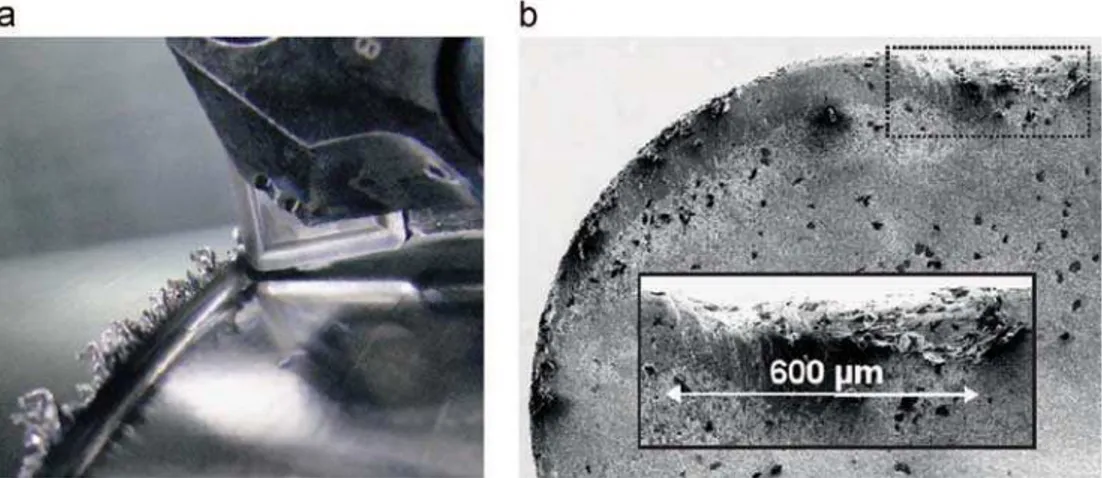
For conventional lubrication conditions, burrs are formed on the work-piece during machining, as shown inFig. 7. At the height corresponding to these burrs, significant notch wear (VBn) is formed. The width of the notch is around 600 μm after 20 min of machining. However, no burrs and no notch wear are visible under high-pressure water jet assistance. The specific effort has a slow and gradual evolution, but it is slightly lower in HPWJA.
4. Roughing tests
Roughing tests were undertaken as per the finishing tests discussed above. Tool wear was measured every 15 s and the tests were continued until a flank wear of 0.3 mm was observed. For conventional lubrication, micro-cracks were noticed on the rake face, and are due to the thermal shock, reflecting the inefficiency of the lubrication. Tool life does not exceed 75 s. Indeed, at the end of this time, the cutting edge collapses completely. Furthermore, the degradation mode is due to plastic deformation of the cutting edge; in fact, it is the result of the combination of high cutting force and high temperature. According to Astakhov [12], plastic deformation of the cutting edge is due to creep deformation at high temperature. This plastic deformation is greater in cobalt because it does not support high creep temperatures. Moreover, this causes the tearing-off of the tungsten carbide grains of the cobalt binder. Fig. 8(b) shows the evolution of creep resistance temperature as a function of stress. When temperature becomes very high in the cutting zone, it creates thermal softening of the tool material so that it can no longer sustain the specific cutting
pressure KC(about 2100 MPa).Fig. 8(a) shows tool rake and flank
faces after 75 s of roughing machining.
The measurement of the cutting force reveals that the average specific pressure is around 2100 MPa in conventional machining.
Fig. 8(b) shows that, to avoid creep in the tool when exposed to a contact pressure of 2100 MPa, the cutting temperature must not exceed 900 1C for the WC and 800 1C for the WC/Co inserts. However, these temperatures correspond to those obtained when machining titanium[13–15]. This result confirms the degradation mode of the cutting edge by creep in conventional machining.
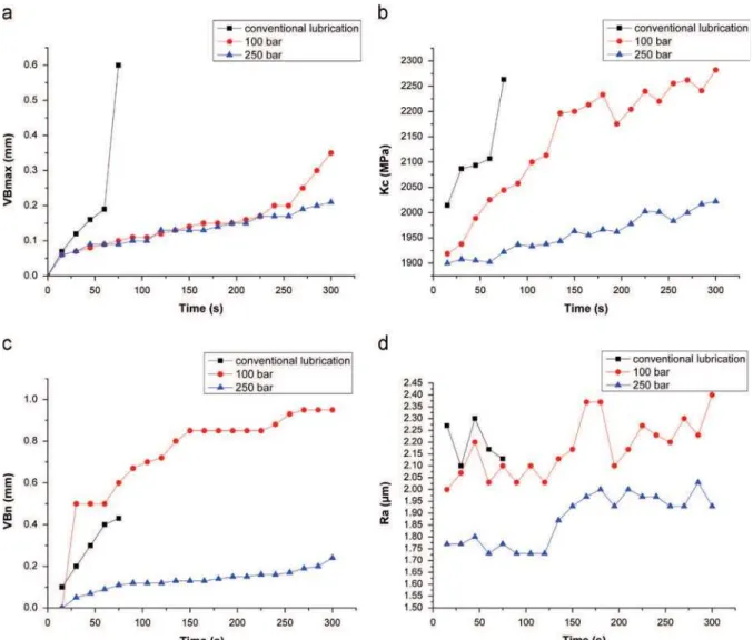
By contrast, for the case of high-pressure water jet assistance, this degradation mode is no longer dominant, the cutting edge does not collapse. This can be explained by the fact that the high-pressure lubrication can greatly reduce the temperature in the cutting zone[16–18]. In addition, the cutting pressure decreases slightly to a value of approximately 1950 MPa.Fig. 9(a) shows that flank wear progresses very quickly under conventional lubrication with rapid collapse of the tool. Under HPWJA, the evolution of flank wear increases slowly and steadily.
This evolution is the same for both assistance pressures. However, from 4 min of machining, wear is accelerated at 100 bars. For a machining time of 5 min, flank wear is around 0.35 mm at 100 bars and around 0.21 mm at 250 bars. For a tool wear criterion set to 0.2 mm, tool life is less than 1 min in conventional machining and about 5 min at 250 bars; so, tool life is multiplied by a factor of 5.
The notch wear, VBn was also observed. Fig. 9(c) shows the evolution of notch wear for the three lubrication configurations in the roughing condition. With conventional lubrication, the notch size increases significantly with machining time. It reaches a value of 0.4 mm when the tool cutting edge collapses. Therefore, the tool degradation mode is the collapse of the cutting edge by plastic deformation, not by notch wear. With water jet assistance at 100 bars, a relatively large notch (0.5 mm) is present from the start of the test and progresses constantly until it reaches 0.95 mm after
Fig. 5. SEM image of the tool rake/flank face after 20 min of machining in the finishing configuration with 100 bars.
5 min of machining. In this case, the water jet pressure does not seem important enough to protect the cutting edge. Conversely, at 250 bars, notch wear is relatively small with a constant increase throughout the test. It reaches only 0.2 mm after 5 min of machining. EDS analysis presented in the section “EDS analysis” shows that the evolution of notch wear is due to the same mechanisms as those of the crater wear.
Fig. 9(b) shows the evolution of the specific cutting pressure versus machining time. The specific cutting pressure seems to increase with increasing tool wear. It can also be noticed that the cutting force under HPWJA is lower than in conventional machin-ing. Indeed, with a pressure of 250 bar, the specific cutting pressure Kc is about 10% lower than in conventional machining
for an unworn tool. This could be due to a decrease in the friction coefficient. Indeed, the lubricant jet is inserted between the chip and the tool, which may change the coefficient of friction. The cooling is mainly localized at the tool and the tool–chip interface. The primary shear zone does not seem significantly cooled.
Fig. 9(d) shows the evolution of the surface roughness. For the three configurations, Ra is generally stable despite a slight tendency to increase over time.
5. Discussion of damage modes and wear 5.1. Phenomena of notch and crater wear
In conventional machining, the chip adheres to the tool rake face and forms deposit layers. The high temperature, coupled with the high contact pressure in this area allows tungsten carbide grains to stick to the underside of the formed coating layer. These adherent layers may protect the rake face from abrasion as well as erosion due
to friction with the chip. But after a period of time, the progressive formation of adherent layers reaches a stagnation level; these layers become unstable and they may even get peeled off. This leads to wear by adhesion. At high-pressure, the jet comes at high speed and pulls out adhering layers, so adhesive wear is strongly activated. Moreover, the tool rake face, which is no longer protected by material deposits, undergoes wear by abrasion and erosion.
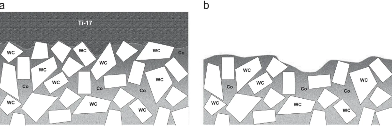
Fig. 10 shows material deposits sticking to tungsten carbide grains. Furthermore, it shows the attrition or loss of carbide grains.
Fig. 11shows that the areas with material deposits are protected and are not subjected to damage.
Fig. 12(a), taken after 4 min of machining, shows layers adher-ing to the notch. After 1 min of additional machinadher-ing, the same notch is observed. Fig. 12(b) shows that the previously observed layers are pulled out, leaving a larger notch. Indeed, significant material loss was noted in the areas where material deposits were located. These observations confirm the wear mechanism by tearing-off of adhering layers.
Xue and Chen[10]observe a similar phenomenon when machin-ing a nickel-based alloy. In fact, the material adheres and sticks to the notch already formed. The accumulation of material results in the instability of the formed material deposits; the sticking material is then pulled out leading to an adhesive wear. In the context of high-pressure water jet assisted machining, stacked layers can be removed by the combination of the jet action and adhesion instability. 5.2. Analysis of material deposits using the EDS technique
To better understand the local phenomena that affects tool wear, the EDS technique was used to examine the material deposits on the tool rake face. For the finishing condition, the analysis was repeated every 5 min of machining. For the roughing
Fig. 7. (a) Formation of burr on the work-piece and (b) notch wear after 20 mm of finishing machining with conventional lubrication.
200 µm
200 µm
Rake face
Flank face
Cutting edge
operation, the control and analysis interval was reduced to 30 s.
Fig. 13shows the results of the qualitative analysis. Three zones can be distinguished.
!
The first is formed by Ti17 layers. This is the sticking andadhesion zone;
!
The second is an area of material abrasion and tearing-off, characterized by localized loss of material (and formation of a crater);!
The last zone is the area that remains intact.In addition, the EDS analyses show the distribution maps of the elements forming the tool and the titanium alloy. The distribution maps of the elements Ti, W, C, Al are presented inFig. 13. It can be seen that increasing the water jet pressure results in a reduction of the adherent layers zone. This reflects a decrease of the zone of strong adhesion and sticking of the chip on the tool rake face. This zone can be related to the tool/chip contact length (LC). Hence, these observations show a decrease in the tool/chip contact length with increasing pressure. The contact length decreases from 180 μm in conventional lubrication, to 74 μm under high-pressure water jet assistance (at 250 bars). In fact, for HPWJA, the fluid infiltrates between the chip and the tool. It has therefore the tendency to separate the chip from the tool rake face, thus decreasing the contact length, LC, and reducing friction between the tool and the chip.
The same measurements have been made for the roughing condition.Fig. 14shows the results of the analysis. Note that for the conventional lubrication condition the results are recorded after 75 s of machining. For both the roughing and the finishing conditions an increase in the jet pressure leads to a decrease in the
Fig. 9. Evolution of (a) flank wear, (b) specific cutting pressure, (c) notch wear, and (d) surface roughness.
Fig. 10. Adherent layers on the tool rake face after 5 min of roughing machining at a pressure of 100 bars.
size of the adherent layers. For example, the percentage of the alloying elements is reduced from 45% for conventional lubrication to 21% at 250 bars for the finishing condition. In all tested conditions, the deposit rate of titanium decreases by about 25% with a pressure of 100 bars and by about 55% with a pressure of 250 bars.
Fig. 15shows the tool rake face of two inserts after 4 min of roughing machining at 100 bars and 250 bars, respectively. It can be seen that the area of the adherent layers becomes smaller when the pressure is increased from 100 bars to 250 bars. In fact, the order of magnitude of the contact length is close to that found in the finishing condition.
Fig. 11. Adherent layers on the tool rake face after 5 min of roughing machining at a pressure of 250 bars.
Fig. 12. Evolution of notch wear in roughing condition: (a) 4 min and (b) 5 min.
5.3. Analysis and discussion
In the finishing condition, catastrophic wear does not appear before 20 min of machining. Flank wear changes slightly. In conventional lubrication, SEM images show a loss of material at the tool nose radius which will lead to local changes in the geometry as well as the nature of the contact. This may explain the degradation of the surface roughness.
Fig. 16illustrates wear by adhesion. In fact, during the tool/chip contact, an interfacial layer of titanium is formed. Combined with the high temperature and high contact pressure, this layer reacts chemically with the tungsten carbide and adheres to the surface of the insert[8,11]. Thus, an increase in the cutting temperature promotes the diffusion between the tool and the chip. This deposed layer seems to protect the tool since the chip is no longer directly in contact with the carbide tungsten. However, after a period of time, the deposit may become unstable and so can be torn off by the chip. In this case, it tears fragments of the tool material leading to wear by adhesion. These findings confirm the results of other studies on adhesive wear of nickel-based alloys. Devillez et al.[19]and Bhatt et al.[11]show via SEM pictures and EDS analysis the formation of a sticky layer; it is to be noted that when this layer is pulled-out, it causes the adhesive wear.
For high-pressure water jet assistance, this phenomenon is accelerated. Some of the material deposits are removed directly by
the water jet. Moreover, when these layers are removed, abrasion wear may occur and erosion by the action of the water jet may be activated. Despite the acceleration of adhesive wear with the high-pressure water jet assistance, flank wear is more stable and only crater wear is accelerated.
This does not affect the global tool life compared to conven-tional lubrication because even if the water jet accelerates crater wear, tool wear is more severe for conventional lubrication. This is due to the lack of lubrication, the higher friction and the higher cutting temperature which leads to the activation of many tool wear mechanisms and causes a higher wear rate.
For the roughing condition, conventional lubrication is not sufficient to cool the cutting zone. In addition, high tempera-tures cause thermal softening of the cutting edge, which is also subjected to very high cutting forces. Under the action of these forces, the cutting edge begins to be deformed by creep. The cutting edge collapses very quickly. However, high-pressure water jet assistance reduces the temperature in the cutting zone. Wear by plastic deformation is avoided, but other mechanisms take place. As in the finishing condition, adhesive wear is accelerated by the action of the water jet. Flank wear is stabilized. This may prevent the deterioration of the surface roughness and the rapid increase in the cutting force. Under these conditions and at a pressure of 250 bars, tool life can be multiplied by a factor of 5. W C Co Ti Al Cr 0 10 20 30 40 50 P e rc e n ta g e ( % ) Elements conventional lubrication 100 bar 250 bar W C Co Ti Al Cr 0 5 10 15 20 25 30 35 40 45 50 55 P e rc e n ta g e ( % ) Elements conventional lubrication 100 bar 250 bar
Fig. 14. Elements percentage: (a) roughing (2 min) and (b) finishing (15 min).
For the finishing and the roughing conditions, the EDS analyses confirm these observations. In fact, the tool/chip contact length decreases when water jet pressure is increased. Moreover, the concentration of alloying elements also decreases. This proves that adherent layers are torn off by the action of the water jet. Furthermore EDS analyses and SEM pictures show that crater wear is more severe when the water jet pressure is increased. The areas where adherent layers still stick to the rake face are not damaged and are not subjected to crater wear.
Like the finishing condition, the acceleration of the crater wear with HPWJA will not reduce tool life compared to conventional lubrication. In fact, in the roughing condition, tool wear is even more severe.
6. Conclusion
This study highlights the impact of high-pressure water jet assistance on tool life for the machining of the Ti17 titanium alloy, for both finishing and roughing conditions. It is seen that under certain conditions, tool life can be multiplied by a factor of five. Basing on EDS analyses and SEM images, different tool wear mechanisms have been identified.
!
Wear by plastic deformation: It dominates when the cutting temperature becomes very high, especially in roughing condi-tions. It is not present under HPWJA;!
Wear by abrasion and adhesion/erosion: It has been observed in all of the machining conditions studied. This type of wear is more present under HPWJA, as titanium deposits are mechanically pulled-out by the action of the water jet and not only by their own instability;!
Notch wear: It was observed for the roughing condition. The main cause of this type of wear is adhesion. Indeed, in the cutting zone, there is a significant release of heat that is favorable to adhesion. Over time, and because of the volatility of the deposits, the notch is formed by tearing-off newly formed adherent layers.In addition, this study shows that the cutting force slightly decreases under HPWJA (approximately 10% at 250 bars for the roughing configuration). This is most probably due to a decrease in the coefficient of friction.
Acknowledgments
The authors would like to thank the French region “Pays de la loire” for funding the project.
References
[1] P. Hartung, B. Kramer, B. von Turkovich, Tool wear in titanium machining, CIRP
Annals 31 (1) (1982) 75–80,http://dx.doi.org/10.1016/S0007-8506(07)63272-7
〈http://www.sciencedirect.com/science/article/pii/S0007850607632727〉. [2] K. Venugopal, S. Paul, A. Chattopadhyay, Tool wear in cryogenic turning of
Ti-6Al-4V alloy, Cryogenics 47 (1) (2007) 12–18, http://dx.doi.org/10.1016/j.
cryogenics.2006.08.011 〈 http://www.sciencedirect.com/science/article/pii/S0-01122750600141X〉.
[3] K. Venugopal, S. Paul, A. Chattopadhyay, Growth of tool wear in turning of Ti-6Al-4V alloy under cryogenic cooling, Wear 262 (9–10) (2007) 1071–1078,
http://dx.doi.org/10.1016/j.wear.2006.11.010 〈http://www.sciencedirect.com/ science/article/pii/S004316480600439X〉.
[4] P. Wanigarathne, A. Kardekar, O. Dillon, G. Poulachon, I. Jawahir, Progressive tool-wear in machining with coated grooved tools and its correlation with
cutting temperature, Wear 259 (7–12) (2005) 1215–1224,http://dx.doi.org/
10.1016/j.wear.2005.01.046〈http://www.sciencedirect.com/science/article/pii/ S0043164805000992〉.
[5]A. Machado, J. Wallbank, I. Pashby, E. Ezugwu, Tool performance and chip control when machining Ti-6Al-4V and inconel901 using high pressure cool-ant supply, Machining Science and Technology (1998) 1–12.
[6]E. Ezugwu, J. Bonney, Effect of high-pressure coolant supply when machining nickel-base inconel 718, alloy with coated carbide tools, Journal of Materials Processing Technology (2004) 1045–1050.
[7]T.B. Bouchnak, Etude du comportement en sollicitations extrêmes et de l'usinabilité d'un nouvel alliage de titane aeronautique: le ti55-3, Ph.D. Thesis, Arts et Métiers Paristech, 2010.
[8]T. Childs, K. Maekawa, T. Obikawa, Y. Yamane, Metal Machining Theory and Applications, Arnold, 2000.
[9]B. Li, A review of tool wear estimation using theoretical analysis and numerical simulation technologies, International Journal of Refractory Metals and Hard Materials 35 (2012) 143–151.
[10] C. Xue, W. Chen, Adhering layer formation and its effect on the wear of coated carbide tools during turning of a nickel-based alloy, Wear 270 (11–12) (2011)
895–902,http://dx.doi.org/10.1016/j.wear.2011.02.018〈http://www.sciencedir
ect.com/science/article/pii/S0043164811000706〉.
[11] A. Bhatt, H. Attia, R. Vargas, V. Thomson, Wear mechanisms of WC coated and uncoated tools in finish turning of inconel 718, Tribology International 43 (5–6)
(2010) 1113–1121, http://dx.doi.org/10.1016/j.triboint.2009.12.053〈http://www.
sciencedirect.com/science/article/pii/S0301679X09003909〉.
[12] V.P. Astakhov, The assessment of cutting tool wear, International Journal of
Machine Tools and Manufacture 44 (6) (2004) 637–647, http://dx.doi.org/
10.1016/j.ijmachtools.2003.11.006 〈http://www.sciencedirect.com/science/arti cle/pii/S0890695503003122〉.
[13] R.R. Rashid, S. Sun, G. Wang, M. Dargusch, An investigation of cutting forces and cutting temperatures during laser-assisted machining of the Ti-6Cr-5Mo-5V-4Al beta titanium alloy, International Journal of Machine Tools and Manufacture 63 (0)
(2012) 58–69, http://dx.doi.org/10.1016/j.ijmachtools.2012.06.004 〈http://www.
sciencedirect.com/science/article/pii/S0890695512001113〉.
[14] M.B. da Silva, J. Wallbank, Cutting temperature: prediction and measurement methods – a review, Journal of Materials Processing Technology 88 (1–3)
(1999) 195–202, http://dx.doi.org/10.1016/S0924-0136(98)00395-1 〈http://
www.sciencedirect.com/science/article/pii/S0924013698003951〉.
[15]M. Kikuchi, The use of cutting temperature to evaluate the machinability of titanium alloys, Acta Biomaterialia 5 (2) (2009) 770–775.
[16] J. Kaminski, B. Alvelid, Temperature reduction in the cutting zone in water-jet assisted turning, Journal of Materials Processing Technology 106 (1–3) (2000)
68–73, http://dx.doi.org/10.1016/S0924-0136(00)00640-3 〈http://www.scien
cedirect.com/science/article/pii/S0924013600006403〉.
[17] C. Courbon, V. Sajn, D. Kramar, J. Rech, F. Kosel, J. Kopac, Investigation of machining performance in high pressure jet assisted turning of inconel 718: a numerical model, Journal of Materials Processing Technology 211 (11) (2011) 1834–1851. Co Co Co Co WC WC WC WC WC WC WC WC WC WC Co Ti-17 Co Co WC WC WC WC WC WC Co
[18] S.Y. Hong, Y. Ding, Cooling approaches and cutting temperatures in cryo-genic machining of Ti-6Al-4V, International Journal of Machine Tools
and Manufacture 41 (10) (2001) 1417–1437, http://dx.doi.org/10.1016/
S0890-6955(01)00026-8 〈http://www.sciencedirect.com/science/article/pii/ S0890695501000268〉.
[19] A. Devillez, F. Schneider, S. Dominiak, D. Dudzinski, D. Larrouquere, Cutting forces and wear in dry machining of inconel 718 with coated carbide
tools, Wear 262 (7–8) (2007) 931–942, http://dx.doi.org/10.1016/j.
wear.2006.10.009 〈 http://www.sciencedirect.com/science/article/pii/S00431-64806003553〉.
![Fig. 1. Types of wear [9].](https://thumb-eu.123doks.com/thumbv2/123doknet/8116797.272389/4.892.212.707.818.1105/fig-types-of-wear.webp)