HAL Id: hal-00162563
https://hal.archives-ouvertes.fr/hal-00162563
Submitted on 13 Jul 2007
HAL is a multi-disciplinary open access
archive for the deposit and dissemination of
sci-entific research documents, whether they are
pub-lished or not. The documents may come from
teaching and research institutions in France or
abroad, or from public or private research centers.
L’archive ouverte pluridisciplinaire HAL, est
destinée au dépôt et à la diffusion de documents
scientifiques de niveau recherche, publiés ou non,
émanant des établissements d’enseignement et de
recherche français ou étrangers, des laboratoires
publics ou privés.
Workspace and Assembly modes in Fully-Parallel
Manipulators : A Descriptive Study
Philippe Wenger, Damien Chablat
To cite this version:
Philippe Wenger, Damien Chablat. Workspace and Assembly modes in Fully-Parallel Manipulators :
A Descriptive Study. ARK, 1998, Austria. pp.117-126. �hal-00162563�
hal-00162563, version 1 - 13 Jul 2007
WORKSPACE AND ASSEMBLY MODES IN
FULLY-PARALLEL MANIPULATORS: A DESCRIPTIVE STUDY
Ph. WENGER AND D. CHABLAT
Institut de Recherche en Cybern´etique de Nantes 1, rue de la No¨e, 44321 Nantes, France
email: [email protected]
Abstract : The goal of this paper is to explain, using a typical example, the
dis-tribution of the different assembly modes in the workspace and their effective role in the execution of trajectories. The singular and non-singular changes of assem-bly mode are described and compared to each other. The non-singular change of assembly mode is more deeply analysed and discussed in the context of trajectory planning. In particular, it is shown that, according to the location of the initial and final configurations with respect to the uniqueness domains in the workspace, there are three different cases to consider before planning a linking trajectory.
Key Words : Parallel Manipulator, Aspects, Singularities, Trajectory Planning,
Assembly Modes, Uniqueness Domains.
1 Introduction
Most of the active research work carried out word wide in the field of parallel ma-nipulators have focused on a particularly challenging problem, namely, solving the forward kinematic problem, or, in other words, finding the different poses of the mobile platform (the assembly modes) in function of the positions of the actuated joints. A second interesting problem has been the evaluation and optimization of the workspace of parallel manipulators (Merlet, 97) and (Gosselin, 88). It is worth noting that the forward kinematic problem and the workspace analysis are most often treated separately, although they are closely linked to each other. It is well known that parallel manipulators have singularities in their workspace where stiffness is lost (Gosselin, 90). These singularities coincide with the set of config-urations in the workspace where two direct kinematic solutions meet (Hunt, 93). On the other hand, it was recently shown that the change of assembly mode could also be accomplished without passing through a singularity (Innocenti, 92). This result gave rise five years later to a theoretical work with the concepts of character-istic surfaces and uniqueness domains in the workspace (Wenger, 97). However, no result has been provided as to the practical interest of these concepts, especially in trajectory planning purposes. The goal of this paper is to explain, using a typical example, the distribution of the different assembly modes in the workspace and
their effective role in the execution of trajectories. The singular and non-singular changes of assembly mode are described and compared to each other. The non-singular change of assembly mode is more deeply analysed and discussed in the context of trajectory planning. This paper is organized as follows. Section 2 recalls the necessary definitions. Section 3 develops the descriptive analysis of this work. A 3-DOF planar manipulator is used as illustrative example all along this study. The 3-D workspace is evaluated and depicted using octree structures. Schematic diagrams are additionally used to improve the legibility of the explanations. Sec-tion 4 yields some ideas on how to use the results of secSec-tion 3 and the uniqueness domains in the purpose of trajectory planning. Section 5 concludes this paper.
2 Preliminaries
In this paragraph, some definitions permitting to understand this paper are quoted.
2.1 FULLY PARALLEL MANIPULATORS
Definition 1 A fully parallel manipulator is a mechanism that includes as many
elementary kinematic chains as the mobile platform does admit degrees of freedom. Moreover, every elementary kinematic chain possesses only one actuated joint. Besides, no segment of an elementary kinematic chain can be linked to more than two bodies (Merlet, 97).
In this study, kinematic chains, or legs (Angeles, 97), are always independent. 2.2 KINEMATIC RELATIONS AND SINGULARITIES
For a manipulator, the relation permitting the connection of input values (q) with output values (X) is the following
F(X, q) = 0 (1)
qis the vector of actuated joints and X is the vector of configurations of the output
link (mobile platform). The set of all admissible q will be referred to as the joint space and the set of all reachable X is the workspace. Differentiating equation (1) with respect to time leads to the velocity model
At+ B ˙q = 0 (2)
Moreover, A and B are respectively the direct-kinematics and the inverse-kinematics matrices of the manipulator. A singularity occurs whenever A or B, (or both) that can no longer be inverted. Three types of singularities exist in general (Gosselin, 90): det(A) = 0 or det(B) = 0 or det(A) = 0 and det(B) = 0.
In this study, only the singularities for which det(A) = 0 (referred to as par-allel singularities (Wenger, 97)), will be of interest. The corresponding singular configurations are located inside the workspace. They are particularly undesirable because the manipulator can not resist any effort.
2.3 NOTION OF ASPECT FOR FULLY PARALLEL MANIPULATORS The notion of aspect was introduced by (Borrel,86) to cope with the existence of multiple inverse kinematic solutions in serial manipulators. In this paper, we will use the notion of aspect defined in (Wenger, 97) for parallel manipulators with only one inverse kinematic solution, which are the object of this study.
Definition 2 The aspects WAi are defined as the maximal sets such that
• WAi⊂ W;
• WAi is connected;
• ∀X ∈ WAi, Det(A) 6= 0
In other words, the aspects WAi are the maximal singularity-free regions in the
workspace.
3 Descriptive Analysis
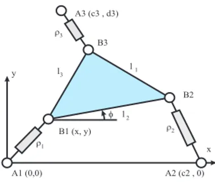
3.1 MANIPULATOR EXAMPLE USED The 3 − RP R parallel manipulator shown
y x A1 (0,0) A2 (c2 , 0) B2 B3 B1 (x, y) A3 (c3 , d3) r3 r1 r2 l3 l1 l2 f
Figure 1: A 3 - RPR parallel ma-nipulator
in figure 1 has been frequently studied (see for instance (Gosselin, 88) and (Innocenti, 92)). The input joint variables are the three pris-matic joints. The output variables are the po-sition and the orientation of the platform in the plane. The passive joints will always be
assumed unlimited in this study. The
lim-its of the prismatic actuated joints are those chosen in (Innocenti, 92) and (Wenger, 97)
(10.0 ≤ ρi ≤ 32.0). The dimensions of the
platform are the same as in (Merlet, 97) and in (Innocenti, 92):
• A1= ( 0.0 ; 0.0) B1B2= 17.04;
• A2= (15.91; 0.0) B1B2= 16.54;
• A3= ( 0.0 ; 10.0) B1B2= 20.84;
3.2 WORKSPACE, SINGULARITIES AND ASPECTS
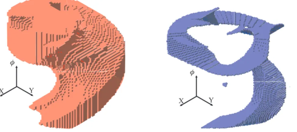
The workspace of the manipulator at hand is 3-dimensional. A 3-D represen-tation can be made in which the vertical axis represents the orienrepresen-tation of the output link in the (x,y)-plane. The workspace is usually analysed in position only (see (Merlet, 98) for instance) and without consideration of the assembly modes. Figure 2 shows the full 3-D workspace modelled with octree structures. Octrees
have nice interesting properties like the existence of an implicit adjacency graph which enables simple connectivity analyses (Wenger, 97) (Samet,79). An efficient calculation technique using octrees has been developed by the authors (Chablat, 97) but is not reported here for lack of space. The dimensions and the displace-ment ranges of the linear actuators are such that the dextrous workspace is non zero. That is, the output link can admit any orientation. In other words, the upper and lower sides of the workspace actually coincide (the workspace has the structure of a torus). Another important feature is that a singular surface lies in-side this workspace and divides it into two adjacent aspects (Sefrioui, 92). When the manipulator output link lies on this singular surface, the manipulator is in a configuration such that the axes on the linear actuators intersect at a common point. Figure 3 shows the singular surface and the two aspects are depicted in
X Y
f
Figure 2: Workspace
X Y
f
Figure 3: The singularity surface
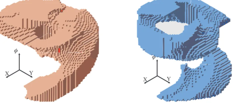
figure 4 and 5, respectively. It is well known that our manipulator admits up to 6 direct kinematic solutions (Gosselin, 92). It was shown in (Wenger, 97) that there are 3 solutions in each aspect. In other words, up to 3 assembly modes are available in a same singularity-free region of the workspace.
3.3 CHANGING ASSEMBLY MODE AND THE STRUCTURE OF THE WORKSPACE
An assembly mode is associated with a solution to the forward kinematics. Changing assembly mode means going from one solution to another. In practice, a change of assembly mode may occur during the execution of a trajectory between two configurations in the workspace which are not necessarily associated with the same input.
Both singular and non-singular assembly mode changes are possible for the ma-nipulator studied. We begin the analysis with the non-singular change of assembly mode. Then, since it was shown recently that it was possible for a parallel ma-nipulator to make it go through a singularity (Nenchev, 97), singular change of assembly mode will be also discussed in this section.
X Y f
Figure 4: First aspect in the Workspace WA1
X Y
f
Figure 5: Second aspect in the Workspace WA2
3.3.1 Non-singular change of assembly mode
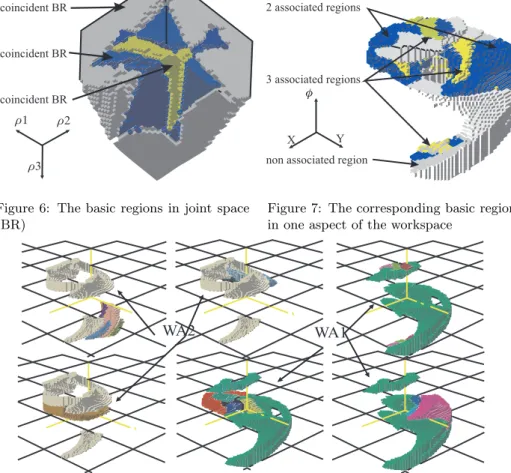
For the purpose of trajectory planning, it is interesting to investigate more deeply when and how a parallel manipulator changes assembly mode without crossing singularities. To begin with, let us examine the topological structure of the workspace. The singularities divide the workspace into aspects and the characteristic surfaces induce a partition of each aspect into a set of regions (the basic regions, see (Wenger, 97)). On the other hand, the singularities also divide the joint space into several regions. Each region of the joint space is characterized by a number, say p, of direct kinematic solutions (or assembly modes) and can be interpreted as being composed of a stack of p coincident basic components. These coincident p basic components are separated under the action of the direct kine-matics to form p disjoint and non adjacent basic regions in the workspace. Such basic regions will be called associated regions and are physically associated to the different admissible assembly modes in one aspect. In figure 6, the joint space is composed of one region with 6 coincident basic components, four regions with 4 coincident basic components and one region with 2 coincident basic components.
In the workspace, the basic components are separated and equally distributed in the two aspects to form, in each aspect, one set of 3 associated regions, one set of 2 associated regions and one basic region which is not associated with another region in the same aspect (figure 7). The uniqueness domains are composed of regions which are not associated. By definition, there is a one-to-one correspon-dence between one uniqueness domain and the joint space. Figure 8 shows the different uniqueness domains obtained for the manipulator studied: there are, in
this case, 3 uniqueness domains in each aspect (WA1and WA2). The important
property of a uniqueness domain is that any displacement of the output link can be accomplished in a whole uniqueness domain while never changing assembly mode. Since the uniqueness domains are, by definition, the maximal sets associated with one assembly mode, it can be claimed that, consequently, the uniqueness domains are the maximal regions of the workspace where all the displacements of the output link can be accomplished while never changing assembly mode.
r3 r1 r2 2 coincident BR
6 coincident BR 4 coincident BR
Figure 6: The basic regions in joint space (BR)
X Y
f
non associated region 2 associated regions
3 associated regions
Figure 7: The corresponding basic regions in one aspect of the workspace
WA1 WA2
Figure 8: The uniqueness domains in the workspace
In contrast, the associated regions are those regions which cannot be linked without changing assembly mode. This means that if the output link must move between two configurations lying in two associated regions, the only way to perform this task is to execute a non-singular assembly mode changing trajectory. Is it always possible to move between two associated regions? The answer is yes if and only if the two regions belong to a same path-connected component of the workspace. As a matter of fact, it is clear that for a motion to exist between two configurations in the workspace, these configurations should belong to a same connected component. Conversely, if it is so, there is a continuous path in the workspace which maps uniquely onto a continuous path in the joint space because the inverse kinematics is continuous and admits only one solution.
We can set the following important result: Each singularity-free domain (or aspect) of the workspace is composed of several uniqueness domains which are associated with one unique assembly mode. Given two points in an aspect, it is
always possible to move between these points if they belong to a same connected component. These points can always be linked without changing assembly mode if they belong to a same uniqueness domain. In contrast, a non-singular assembly mode trajectory will have to be executed if the two points belong to the associated regions of two distinct uniqueness domains.
This result is of primary importance since according to the location of con-figurations in the workspace, the trajectory planning will not have to be equally treated. In the case of two configurations lying in a same uniqueness domain, any continuous trajectory is feasible in this domain since, by definition, there is a one-to-one correspondence between the uniqueness domain and the joint space. On the other hand, if the two points belong to two distinct uniqueness domains (that is, in two associated regions), the problem is different since the trajectory will have to enable a change of assembly mode. Now, we will explain how a non-singular change of assembly mode can be realised. When a motion is prescribed between two associated regions, a specific trajectory must be executed in the joint space. This trajectory must link the two coincident basic components of the joint space corresponding to the two associated regions in the workspace. It can be shown, using a similar analysis as for cuspidal serial manipulators (Wenger, 96), that the coincident basic components are not directly connected by their boundaries, but through an adjacent component where the number of direct kinematic solutions is lower. Thus, a typical non-singular assembly mode changing trajectory is not a straightforward path inside the joint space. Instead, it will be a trajectory that will leave the initial basic component through a boundary surface, transits through an intermediate adjacent component and finally enters the goal basic component (which is actually coincident to the initial one) by crossing a different boundary surface. In the workspace, a non-singular assembly mode changing trajectory al-ways crosses at least two characteristic surfaces (which are associated with the boundary surfaces crossed in the joint space) and a basic region which is not as-sociated with the initial and final regions. Such a manoeuver is illustrated in solid lines in figure 9. In the same figure, the dotted lines show the path in the workspace that would result from a direct trajectory in the joint space. This path starts from the initial prescribed configuration but does not reach the desired goal configuration since the assembly mode has not changed. From a practical point of view, this means that trajectories should be planned in the workspace rather than in the joint space. We will come back on this point in section 3.4.
3.3.2 Singular change of assembly mode
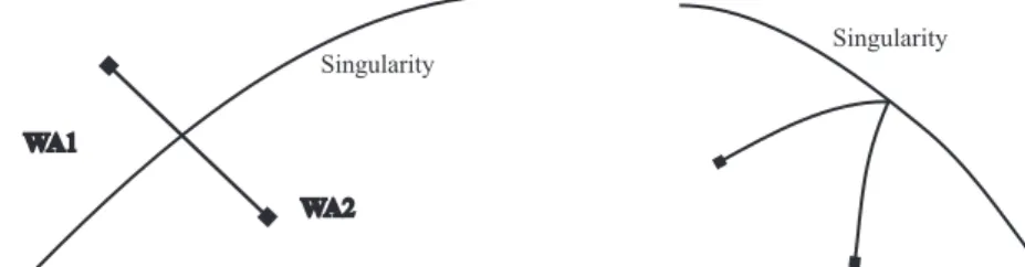
A singular change of assembly mode implies going through a singularity where the manipulator looses stiffness. For a long time, it has been commonly argued that such a manoeuver was not possible in practice because of the lost of control at the singularity. However, Nenchev et al have shown recently that it was possible to control the motion of a parallel manipulator through a singularity under certain conditions on the instantaneous direction of motion of the output link (Nenchev, 97). A singular change of assembly mode will be necessary when the two con-figurations to be linked are located in two distinct aspects in the workspace, like
2 DK solutions 1 DK solution
3 DK solutions
Joint space
Workspace
Figure 9: Right (solid) and wrong (dotted) trajectories (scheme)
in figure 10. When the output link crosses a singularity, it can be shown that the corresponding joint trajectory “reflects back” against a boundary in the joint space, which is the image of the singularity crossed in the workspace (figure 11). As a matter of fact, given a vector of actuated joint position near a singular-ity, (Innocenti, 92) has shown that there are two “related configurations” in the workspace which are symmetrically located with respect to the singularity in the workspace and these two related configurations merge at the singularity. Thus, in contrast with 3.3.1, a singular assembly mode changing trajectory gives rise to a joint trajectory which links two coincident basic components directly by their boundary. This joint trajectory is analogous to the cartesian singular change of posture trajectory of a “Puma” serial manipulator when it switches from “elbow up” to “elbow down”.
Singularity
WA1
WA2
Figure 10: Two configurations in two dis-tinct aspects in workspace
Singularity
Figure 11: Singular assembly mode chang-ing joint trajectory
3.3.3 Application to the trajectory planning
This section only provides some key ideas on how the previous analysis and the octree model of spaces can be applied to the trajectory planning. We assume here for more simplicity that there is no collision so that the aspects and the uniqueness domains are connected (Wenger, 97). However, we know that the workspace is not necessarily connected even if all motions are free of collisions. So, the first thing to do is to verify whether the two configurations belong to the same connected component of the workspace. This test can be done easily with the octree model of the workspace using a path-connectivity analysis algorithm (Samet, 79). If the two configurations are not in a same connected component, no trajectory can be
found. If yes, according to the preceding analysis, there are three main cases to consider:
• 1. the two configurations are in two distinct aspects
• 2. the two configurations are in a same aspect but in two distinct uniqueness
domains
• 3. the two configurations are in a same uniqueness domain.
All cases can be easily checked using the octree models of the aspects and of the uniqueness domains. In the first case, we are in a situation where a singular change of assembly mode is necessary. In this case, the analysis of (Nenchev, 97) should be used to build a path which permits a feasible control law. In the second case, a non-singular change of assembly mode will have to be executed. A path must be constructed in the workspace. For the calculation of the corresponding path in the joint space, a simple method is to compute the inverse kinematics for a series of configurations by discretisation of the workspace path, without omitting those configurations where the output link crosses the characteristic surfaces. The last case is the nicest situation since we can remain in a same uniqueness domain and the kinematics is one-to-one between the joint space and the uniqueness domain. In this case, it is possible to compute a feasible trajectory directly in the joint space, which is more convenient for optimizing certain criteria (like the actuator torques or the cycle time for instance). Under all circumstances, the search for a feasible path can be achieved with classical tools using the octree structures (see (Faverjon, 84) for instance). The well-known A* algorithm can be used, together with a path cost estimation procedure (on the basis of a chosen relevant criteria).
4 Conclusion
The descriptive study provided in this paper has shown the interest of defining and calculating the aspects and the uniqueness domains in the workspace for trajectory planning. A change of assembly mode will be necessary when and only when the initial and goal configurations are not in a same uniqueness domain. Such manoeuvres are possible if and only if the two configurations are in a same connected component of the workspace. A non-singular change of assembly mode will occur between two configurations which are in two distinct uniqueness domains but in a same aspect while a singular change of assembly mode is only necessary when the configurations are in two distinct aspects. It is of interest to know in advance whether two given configurations will be linked with or without a change of assembly mode. It is more desirable to plan trajectories that keep the same assembly mode since such trajectories will generally lead to smoother displacements of the actuated joints. That is, the working configurations should be located in a same uniqueness domains, which could be garanteed by a proper placement and/or design of the manipulator. This work brings also some new ideas for the optimal design of parallel manipulators: it is more convenient to have a
manipulator with large uniqueness domains rather than with a large workspace since a large workspace can be composed of many small uniqueness domains. A planar manipulator has been used to illustrate this work but the tools developed with octree structures permit to treat any 3-DOF fully-parallel manipulators like spatial positioning manipulators. Work is under development to take into account the effects of collisions (between legs and with obstacles) in the calculation of the uniqueness domains.
5 References
Angeles, J., (1997), Fundamentals of Robotic Mechanical Systems, SPRINGER. Borrel, P., (1986), A study of manipulator inverse kinematic solutions with applica-tion to trajectory planning and workspace determinaapplica-tion, Proceeding IEEE Internaapplica-tional Conference on Robotic And Automation, pp 1180-1185.
Chablat, D., and Wenger, Ph., (1997) Domaines d’unicit´e des manipulateurs par-all`eles, IRCyN Internal Report, N◦96.13, Nantes.
Faverjon, B., (1998), Obstacle avoidance using an octree in the configuration space of a manipulator, 1st I.E.E. Conference on Robotics and Automation, Atlanta, pp. 504-512. Gosselin, C., and Angeles, J., (1988), The Optimum Kinematic Design of a Planar Three-Degree-of-Freedom Parallel Manipulator, ASME, Journal of Mechanisms, Trans-missions, and Automation in Design, Vol. 110, March.
Gosselin, C., and Angeles, J., (1990), Singularity analysis of closed-loop kinematic chains, IEEE Transactions On Robotics And Automation, Vol. 6, No. 3.
Gosselin, C., Sefroui, J., and Richard M. J., (1992), Solutions polynomiales au probl`eme de la cin´ematique directe des manipulateurs plans `a trois degr´es de libert´e, Mechanical and Machine Therory, Vol. 27, No. 2, pp 107-119.
Hunt, K. H., and Primrose, E. J. F., (1993), Mechanical and Machine Theory, Vol. 28, No 1, pp. 31-42.
Innocenti C., and Parenti-Castelli V., (1992), Singularity-free evolution from one con-figuration to another in serial and fully-parallel manipulators, Proceeding ASME Design Technical Conferences, DE-Vol. 45, Robotics, Spatial Mechanisms and Mechanical Sys-tems, pp. 553-560, ASME.
Merlet, J-P., (1997), Les robots parall`eles, HERMES, seconde ´edition, Paris.
Merlet, J-P., Gosselin, C., and Mouly, N., (1998), Workspaces of Planar Parallel Manipulators, Mechanical and Machine Theory, Vol. 33, No. 1/2, pp 7-20.
Nenchev, D.N., Bhattacharya, S., and Uchiyama, M., (1997), Dynamic Analysis of Parallel Manipulators under the Singularity-Consistent Parameterization, Robotica, Vol. 15, pp. 375-384.
Samet, H., (1979), Connected component labeling using quadtrees, Computer Science Department, University of Maryland, College Park.
Sefrioui, J., and Gosselin, C., (1992), Singularity Analysis and representation of planar parallel manipulators” Robotic and Autonomous Systemes 10, pp. 209-224.
Wenger, Ph., and Chablat, D., (1997), Uniqueness Domains in the Workspace of Parallel Manipulators, IFAC-SYROCO, Vol. 2, pp 431-436, 3-5 Sept., Nantes.
Wenger, Ph., and El Omri J., (1996), Changing Posture for Cuspidal Robot Manipu-lators, International Conference on Robotics and Automation, Minneapolis, Minnesota, pp. 3173-3178.