HAL Id: hal-01065275
https://hal.archives-ouvertes.fr/hal-01065275
Submitted on 18 Sep 2014
HAL is a multi-disciplinary open access
archive for the deposit and dissemination of
sci-entific research documents, whether they are
pub-lished or not. The documents may come from
teaching and research institutions in France or
abroad, or from public or private research centers.
L’archive ouverte pluridisciplinaire HAL, est
destinée au dépôt et à la diffusion de documents
scientifiques de niveau recherche, publiés ou non,
émanant des établissements d’enseignement et de
recherche français ou étrangers, des laboratoires
publics ou privés.
Optimal control strategies of a double stator permanent
magnet generator applied in tidal current energy
extracting
Jian Zhang, Luc Moreau, Mohamed Machmoum
To cite this version:
Jian Zhang, Luc Moreau, Mohamed Machmoum. Optimal control strategies of a double stator
per-manent magnet generator applied in tidal current energy extracting. Symposium de Génie Électrique
2014, Jul 2014, Cachan, France. �hal-01065275�
SYMPOSIUM DEGÉNIEÉLECTRIQUE(SGE’14) : EF-EPF-MGE 2014, 8–10JUILLET2014, ENS CACHAN, FRANCE
Optimal control strategies of a double stator
permanent magnet generator applied in tidal current
energy extracting
Jian ZHANG, Luc MOREAU, Mohamed MACHMOUM
IREENA, Université de Nantes, Boulevard de l’Université, 44602 Saint-Nazaire, France
ABSTRACT – This paper investigates the efficiency difference of a double stator permanent magnet generator controlled by three vector current control strategies (maximum torque per ampere control, unity power factor control and constant flux control) in a direct drive tidal energy system. The work will focus on the tidal speed below its rated value. The rotational speed of turbine is proportional with tidal speed to maximize the power coefficient. For the same rotational speed, the generator power loss (including converter loss) is different when it is controlled by different control strategy. Through calculating the generator efficiency under the three control condition, an optimal control strategy can be chosen for special turbine rotational speed or tidal current speed.
KEY-WORDS – Vector current control, double stator permanent magnet generator, converter power loss, tidal energy
1. INTRODUCTION
The most important characteristics for resource used for ge-nerating electricity are sustainability and predictability. An as-sessment of exploitable sites in Europe with strong tidal currents yielded a total energy potential of about 105 TWh/year. This potential is mainly in the United Kingdom (50 TWh/year) and France (44 TWh/year). The global tidal energy potential is about 5∼10 times the European potential [1]. The tidal current energy resource has a major advantage over other renewable energy re-sources, as it is predictable over long time scales. Further more, tidal current turbine farms have little visual impact since tidal current turbines and the auxiliary facilities have their main parts submerged underwater. The method to harness tidal current po-wer is based on the technologies of wind turbine and ship pro-pellers which are relatively mature [2]. However, the investment of tidal power plant construction is much higher than wind po-wer even though some tidal projects have already reached a rela-tively mature stage in the last decade. Therefore, improving the cost performance is a valuable research subject for tidal plant projects.
Direct drive permanent magnet generator with fully rated po-wer electronics interface system has been proven as a good se-lection in the long run in terms of low maintenance cost and po-wer output quality enhancement. Moreover, fully variable speed operation has benefit of increasing tidal farm efficiency [3]. In order to increase the power system efficiency, the permanent magnet generator should be designed in a optimized way and be controlled with a optimal strategy. In the paper [4], authors provide a machine optimization methodology which includes the power loss of machine and converter over a torque speed operating profile for wave energy application. Attempts to
mini-mize the power loss on PM synchronous motor drives through control strategies are researched in [5–7]. An effort to specify the loss minimization control for surface and interior PM syn-chronous motor drives is presented in [5]. However, the realiza-tion of this method strongly depends on the machine parameter. Consequently, the suggested method is implemented by using a lookup table where a number of costly and time-consuming measurements for each motor are required. Such measurements are practically impossible on motors already in operation and, therefore, the method is not widely applicable. Through control the machine power factor equal to around one, the author saved energy [6]. However, this method needs to adjust the machine frequency to realize the implementation. On the other hand, converter power losses are neglect in their research. For a mega-watt rate machine, the converter losses should be considered for optimal machine design and control [4]. In order to take account of converter loss model to choose the control strategies, this pa-per will only discuss three special control strategies which redu-ced the complexity of the power factor calculation.
This paper will mainly research the efficiency of a double stator permanent magnet generator including the losses of the AC/DC PWM rectifier when the tidal speed is under the rated value (0.6m/s∼2.7m/s). A 1MW fixed pitch control tidal tur-bine model is discussed in the first part. Then the generator and converter losses model are given. Comparison of generator ef-ficiency under three control strategies is fulfilled. The results confirm that by only changing the control strategy of rectifier we can improve the system efficiency.
2. TIDAL TURBINE MODELING
The technologies used to extract most of renewable energy are closely dependent on the characteristics of the resource. Un-doubtedly, some basic understanding of the tidal resource dyna-mics is therefore one of the first steps to be considered before exploiting it.
The energy contained in the tidal current is in the form of kinetic energy like wind power. Therefore, the output power of a tidal current turbine has a similar dependence as a wind turbine and is expressed by the following equation [8] :
P = 1
2ρCpπRb
2
v3t (1)
Where ρ is the fluid density, Rbis the turbine blade radius and vt
is the tidal current velocity. Cpis known as the power coefficient
from the tidal current stream and is explained by Betz’law. The power coefficient Cpis a function of tip speed ratio λ and
tur-bine blades pitch adjustment angle β. For a fixed pitch turtur-bine, β keeps constant as 0. The tip speed ratio is defined as :
λ = Rbωm vt
(2) Where ωm(rad/s) is the mechanical rotational speed of rotor.
Through controlling the value of tip speed ratio λ and turbine blades pitch angle β, the power coefficient Cp can be
regula-ted. For wind generators, Cp has typical values in the range
0.25∼0.5. The upper limit is for highly efficient machines with low mechanical losses. For marine turbines, Cpis estimated to
be in the range 0.35∼0.5 [9]. Each tidal current speed has a re-lative turbine rotational speed to achieve maximum energy ex-tracting as Fig. 1 shown.
Fig. 1. Optimal operating point
Fig. 2 presents the power harnessed by turbine for the variable tidal current velocities. The power between cut in speed Viand
rated speed Vrfollows the optimal operating points
characteris-tic. There is no cut out speed for tidal current turbines, since the tidal current speed is predictable. Secondly, even the most ex-treme currents caused by storm surges imposed on the highest spring tides are normally not that much greater than the monthly maximum spring tidal currents. In the contrary, the wind turbine must be designed to handle the 100 year peak wind speed which is several times greater than typical monthly maximum wind speed.
Fig. 2. Power curve of tidal turbine
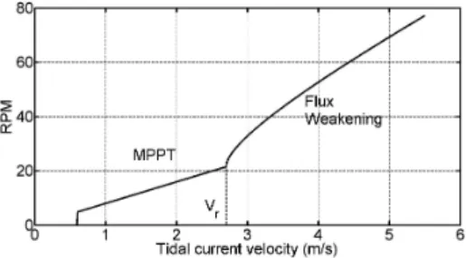
When the tidal speed is under the rated value, the turbine ro-tational speed is controlled in proportional manner with tidal speed to keep tip speed ratio value as constant. This value is considered as the optimal tip speed ratio (λopt) for realizing
maximum power point tracking (MPPT) under rated tidal cur-rent speeds. Through control the tip speed ratio equal to opti-mal value, maximum power is extracted from the tidal kinetic energy. When tidal speed is over the rated speed, for a fixed pitch turbine, the current used method to realize the power
limi-tation is flux weakening control [10]. In this speed region, the power coefficient of tidal turbine Cpwill decrease as the turbine
rotational speed increase. The rotational speed and torque cha-racteristic of turbine are showed in Fig. 3 and Fig. 4 respectively.
Fig. 3. Turbine rotational speed curve
Fig. 4. Torque characteristic of a fixed pitch turbine
3. GENERATOR AND POWER LOSS MODEL
Double Stator Surface Mounted Permanent Magnet Genera-tor (DSSMPMG) has been designed to serve as the integrated starter generator for HEVs and wind energy application, which is claimed to offer much higher power volume density than tra-ditional PMSG. In tidal energy or wind energy system, volume of generator is an very important issue for the project designer. It may cause problem of transportation and installation. Big ge-nerator volume may reduce the power extracting as it is fixed be-hind the turbine blades. After the tidal or wind current flowing through the blades, generator nacelle prevent the current pas-sing smoothly. It reduces the current speed and so as to power extracting. Actually, DSSMPMG has much more merits such as smaller cogging torque, smaller rotor inertia and higher redun-dancy comparing with traditional PMSG [11]. Based on those advantages, DSSMPMG can be well suited for tidal current energy extracting. Fig. 5 shows one possible system topology of DSSMPMG [12]. The cup shape rotor is in the middle of the inner and outer stator. Permanent magnets are mounted on the surface of two sides of rotor. The two stators are connected to two back-to-back converters and are controlled in parallel. The total torque of the generator is the superposition of the torque of inner and outer stator. DSSMPMG also can be controlled in se-ries using one back-to-back converter with the two stators phase winding connected in series.
The permanent magnet can be surface mounted on the cup rotor or interior buried in the rotor. In [13], the authors quantita-tively compared both steady and dynamic performances among the double stator surface mounted PM generator, double stator interior PM generator and traditional single stator PM genera-tor. The comparison results confirms that double stator surface
Fig. 5. Two stators controlled in parallel
mounted PM generator has better performance. In the mecha-nical point of view, interior PM generator is suitable for high rotational speed application. However, in the tidal current tur-bine application which normally rotated in low speed, surface mounted PM generator is robust enough.
3.1. Generator model
The polarization direction of the magnet can be reversed (N-N type) or in the same direction (N-S type). In our case, in order to control the two stators independently, N-N type surface mounted permanent magnet double stator generator are designed. In this double stator generator topology, in the Fig. 6, the flux paths are in parallel between the two stator. Magnetic flux will travel from single side of stators, namely through the same side air-gap and the rotor core, and then return to the initial stator. And the two flux paths will pass inside of the rotor core. There is no mutual flux between the two set stator windings. Therefore, the double stator generator model can be regarded as the superposition of two traditional PM machine.
Fig. 6. Flux line with load in two stator (N-N type).
The generator is analyzed in synchronously rotating d-q refe-rence frame : vdx= Rsxidx− ωeLqxiqx+ Ldx didx dt (3) vqx= Rsxiqx+ ωe(Ldxidx+ ψrx) + Lqx diqx dt (4)
In the equation above, the subscript x can be replaced by o and i which mean outer stator and inner stator respectively. idxand
iqxare the stator currents, Rsxis the stator winding resistance,
Ldxand Lqxare the stator direct and quadrature inductances, ωe
is the stator electrical rotational speed and ψrxis the excitation
flux linkage of PM. Inner stator inductance is slightly bigger than that of the outer stator since the leakage inductance of inner stator is bigger than that of outer stator. The electric torque of stators can be given as :
Tex=
3
2piqx[idx(Ldx− Lqx) + ψrx] (5) The total torque of the generator can be expressed as :
Ttot= Tei+ Teo (6)
For surface mounted permanent magnet generator, the d-q axis inductance is equal. Therefore, Eq. 6 can be rewritten as :
Ttot=
3
2p(ψroiqo+ ψriiqi) (7)
3.2. Generator and converter power losses model 3.2.1. Generator power losses
The generator outer and inner stator power losses model are the same. The total copper loss in one stator is :
Pculoss= 3Is2Rcu (8)
The resistance Rcu of one phase is determined from the set of
geometric parameters. Copper resistivity is set at 115◦.
For the iron losses, we will apply the principle of separa-tion of losses, including both hysteresis losses and eddy current losses. Additional losses due to magnetic anomalies, metallur-gical and manufacturing processes have been taken into account by introducing a factor of additional core losses (Kad) [14].
Ma-gnetic losses will be calculated using the following classical for-mula :
Piron= Kad(kecp2ωm2 + khpωm)Vol(y or t)Bp(y or t)2 (9)
where kec and kh are the specific loss coefficients for eddy
currents and hysteresis, respectively. Losses in both the yoke (Pironyoke) and teeth (Pironteeth) are separately considered. ωm
is the mechanical rotational speed in rad/s. p is the number of pole pairs. Vol(y or t)and Bp(y or t)are the iron volume and
si-nusoidal peak flux density for a specific part (teeth or york) res-pectively. The orthoradial component of the peak flux density in the yoke Bpyand the radial component in the teeth Bptare
cal-culated depending on the geometry of the machine and air gap peak flux density value Bp. Bpcan be approximately calculated
as : Bp= √ 2V ωmNskbDL (10) Where V is the phase terminal voltage. Ns is the number of
turns of winding and kb is the winding factor. D and L are the
generator bore diameter and length. 3.2.2. Converter power loss
Power Losses in the electronic power converter (PWM AC/DC rectifier) are composed of the sum of conduction loss
(Eq. 11) and switching loss Eq. 12 both in diodes and IGBT. Pcond,k= V0,kIav,k+ Rd,kIRM S,k2 (11)
where k is the component under consideration (diode or IGBT), V0,k the threshold voltage of the device k and Rd,k its
dyna-mic resistance. Iav,k and IRM S,k are respectively the average
and RMS current passing through the device k. They depend on not only the RMS current per phase Isand terminal voltage V
but also on the phase difference between these two quantities. Further more, they also depend on the modulation ratio.
Switching losses are assumed to be proportional to the swit-ched current :
Psw=
√
2fsw(Bsw,rec)IRM S/π (12)
where Bsw,recis the switching and recovery losses coefficient
in the IGBT and diode. The hypothesis will be adopted whereby for a given maximum voltage rating (here 3300V ), this coeffi-cient remain independent of the maximum current rating of the switch.
Observations from manufacturers’ documentation enable de-ducing, for a given maximum voltage rating (here 3300V ), the scale law as a function of the maximum current rating of the two components :
Rd,k= rd,k/(
√
2Irated) (13)
Table 1. Constant parameters used in the power losses model [4][14] Symbol Description Value
Kad factor of additional core losses 15
kec Eddy current loss coefficient 6.5×10⁻³W s2/m3T2
kh Hysteresis loss coefficients 15W s2/m3T2
L Length of the generator 0.578m p Number of pole pairs 40 V0,IGBT Threshold voltage of IGBT 2V
V0,diode Threshold voltage of diode 1.7V
rd,IGBT Dynamic resistance of IGBT 1500mΩ/A
rd,diode Dynamic resistance of diode 1000mΩ/A
fsw Switching frequency 2kHz
Bsw, rec Switching and recovery losses coefficient
3mJ/A
4. VECTOR CURRENT CONTROL STRATEGIES
Vector current control is commonly used in direct drive per-manent magnet generator system [15]. The quadrature axis cur-rent reference is obtain by speed controller output, but the direct axis current reference can be modified in different manners so the generator has different characteristics.
There are three vector current control strategies which are usually chosen for controlling the permanent magnet generator as Fig. 7 shown. Each strategy has advantages and disadvan-tages due to generator working condition and delivered power. The first strategy is maximum torque per ampere control shown in Fig. 7(a). The phase current in this control strategy is the lo-west current produced compared with the other strategies, which gives minimum copper loss at stator windings. But, the terminal voltage is always higher than the EMF which leads to higher core loss. The second strategy is unity power factor control. In this strategy we maximize the power factor to one that will give
(a) Maximum torque per ampere control
(b) Unity power factor control
(c) Constant flux control Fig. 7. Vector current control strategies
us the highest current among these three strategies which will affect generator’s copper loss. At the same time, from vector analysis, this strategy will always has lower terminal voltage than EMF that will give us the lowest core losses among other strategies. The third strategy is constant flux control, which is a compromise of the other two strategies. The terminal voltage is at the same value with EMF and the phase current is control-led at the middle between them. The resistive voltage drop is neglected in the vector diagram.
5. RESULT
Our results will mainly focus on the low tidal speed region. For the speed above the rated value, flux weakening control is a solution to keep the generator operated at nominal power for a fixed pitch control turbine. Two stators are separately controlled in the same manner.
Fig. 8. Three control method efficiency
Fig. 8 shows the efficiency curves of generator which ope-rates under three different vector current control strategies. We
can see that in the speed region 0.6m/s∼1.84m/s, unity power factor control method can obtain maximum efficiency. Then, constant flux control is the best method in the speed interval of 1.84m/s∼2.6m/s. However, the most commonly used and simple control strategy id = 0 or maximum torque per ampere
control has the best performance only in a small interval near the rated tidal speed (2.7m/s). From the enlarged figure we can see that if we select the control method of generator appropriately, we can improve the system efficiency almost 1% in a wide tidal speed range. The total power loss varies about 10% between the control strategies.
Table 2. Optimal control strategy for different tidal speed region
Tidal current speed (m/s) 0.6∼1.84 1.84∼2.6 2.6∼2.7 Optimal control strategy Unity power factor control Constant flux control Maximum torque control
Fig. 9. Power losses variation
Table. 2 states that there is a optimal control strategy to achieve a better system efficiency for a special tidal current speed range. The details of power losses information for each control strategy region are given in Fig. 9. When the speed is between 0.6m/s∼1.84m/s, iron loss is the main part of power losses. The unity power factor control strategy which can de-crease the iron loss will improve the efficiency of the generator. On the contrary, in high speed region 2.6m/s∼2.7m/s, copper loss is the main part of power losses. Maximum torque per am-pere control is priority compared with other two strategies even it increases the iron loss because of that it reduces the copper loss sharply. The choice of constant flux control in speed range 1.84m/s∼2.6m/s is a compromised result of iron loss and cop-per loss. Switching loss and conduction loss of converter has a little impact on the selection of control strategy.
6. CONCLUSION
This paper presents the efficiency difference of a DSSMPMG with two stators controlled in parallel under three vector cur-rent control strategies condition. For the same turbine delive-red power and rotational speed, there is an optimal control stra-tegy to obtain a better system efficiency. The generator side converter power loss has been taken into account. The results show that unity power factor control and constant flux control are the best choice for tidal speed region 0.6m/s∼1.84m/s and 1.84m/s∼2.6m/s respectively in our case. However, the most simple and frequently used control method in laboratory id= 0
or maximum torque per ampere control has the best perfor-mance only in a small speed interval 2.6m/s∼2.7m/s. Through only changing the control strategy of the generator based on the tidal speed, the system can deliver more power to the grid. Fu-ture work will focus on the dimensioning and dynamic control model of DSSMPMG.
7. REFERENCES
[1] T.J. Hammons, « Tidal power in the UK and worldwide to reduce green-house gas emissions », International Journal of Engineering Business Ma-nagement, May 2011.
[2] S. Benelghali, M.E.H. Benbouzid, J.F. Charpentier, « Marine tidal current electric power generation technology : state of the art and current status », Electric Machines & Drives Conference, IEMDC’07. IEEE International, vol.2, no., pp.1407–1412, May 2007.
[3] A. Blavette, « Grid integration of wave energy and generic modelling of ocean devices for power system studies », PhD Dissertation of University College Cork, 2013.
[4] J. Aubry, H.B. Ahmed, B. Multon, « Sizing Optimization Methodology of a Surface Permanent Magnet Machine-Converter System over a Torque-Speed Operating Profile : Application to a Wave Energy Converter », IEEE Transactions on Industrial Electronics, 2011.
[5] S. Morimoto, Y. Tong, Y. Takeda, and T. Hirasa, « Loss minimization control of permanent magnet synchronous motor drives », IEEE Trans. Ind. Electron., vol. 41, pp. 511–517, Oct. 1994.
[6] Y. Nakamura, T. Kudo, F. Ishibashi, and S. Hibino, « High-efficiency drive due to power factor control of a permanent magnet synchronous motor », IEEE Trans. Power Electron., vol. 10, pp. 247–253, Mar. 1995.
[7] C. Mademlis, J. Xypteras, N. Margaris, « Loss minimization in surface permanent-magnet synchronous motor drives », IEEE Transactions on In-dustrial Electronics, vol.47, no.1, pp.115,122, Feb 2000
[8] B. Whitby, C.E. Ugalde-Loo, « Performance of pitch and stall regulated tidal stream turbines », IEEE Transactions on Sustainable Energy, vol. 5, no. 1, January 2014.
[9] S. Benelghali, « On multiphysics modeling and control of marine cur-rent turbine systems », Thése de Université De Bretagne Occidentale, Dé-cembre 2009.
[10] Z.B. Zhou, F. Scuiller, J.F. Charpentier, M. Benbouzid, T.H. Tang, « Po-wer limitation control for a PMSG-based marine current turbine at high tidal speed and strong sea state », Electric Machines & Drives Conference (IEMDC), 2013 IEEE International , vol., no., pp.75,80, 12-15 May 2013 [11] S.X. Niu, « Design, control and application of double-stator permanent magnet brushless machines », PhD dissertation of the university of Hong Kong, 2009.
[12] J. Zhang, L. Moreau, M. Machmoum, P.E. Guillerm, «State of the Art in Tidal Current Energy Extracting Technologies », International Conference on Green Energy, March 2014.
[13] S.X. Niu, K.T. Chau, and C. Yu, « Quantitative comparison of double sta-tor and traditional permanent magnet brushless machines », American Ins-titute of Physics, 2009.
[14] N. Bernard, F. Martin, M.E. Zaim. « Design methodology of a permanent magnet synchronous machine for a screwdriver application », IEEE Tran-sactions on Energy Conversion, Sept 2012.
[15] R. Krishnan, « Permanent magnet synchronous and brushless DC motor drives », Taylor & Francis Group, 2010.