PHYSICAL METALLURGY OF A HSS MATERIAL FOR HOT ROLLING MILL ROLLS Jacqueline LECOMTE-BECKERS 1
Jerome TCHOUFANG TCHUINDJANG1
Eric PIRARD2
Jean-Pierre BREYER3
ABSTRACT
High Speed Steel (HSS) cast rolls are used in front finishing stands of hot strip mills. Good wear resistance and hardness at high temperatures, are defining features of HSS.
Many types of carbides are present in these alloys, each having different effect upon their final properties. As a result, nature, morphology and amount of these carbides are factors of important concern.
Identification and characterisation of carbides were realised. MC, M2C, M7C3 carbides were found. Some
relationships with mechanical properties were obtained especially in the field of the solidification sequence that affects grain size and carbides dispersion.
Key words: carbides, microscopic identification, HSS.
1. INTRODUCTION.
In order to adapt to severe hot rolling conditions of a Hot Strip Mill, a rolling mill roll with much higher resistance to wear and surface roughening has always been searched. In the beginning of the 1990’s a challenge was launched to rollmakers to develop a product capable of better satisfying the ever-increasing requirements for rolling mills with regards to strip’s surface quality appearance and for better productivity of the rolling mills. The work roll performance in the Finishing Mill has a direct impact on the following major cost aspects:
• Strip surface quality, rolled-in scale which may be caused by the rough surface of the rolls
• Plant utilisation, lengths of rolling programs which is influenced by the frequency of rolls change causing lost of rolling time
• Productivity of rolls in ton/mm, controlled by roll wear and minimum dressing required after each roll campaign
• Workload in the Roll Shop, number of work rolls changes resulting in excessive workload in the roll shop.
A compound roll with the outer layer made of high alloyed steel corresponding to the family of alloys used for cutting tools, which is called HSS rolls was developed and High Speed Steels (HSS) rolls were introduced into hot strip mills in Japan in the early nineties. This new roll has spread all over the mills in Japan quite quickly, even over many mills such in Europe and USA, to replace the Hi-Cr rolls used in the first Finishing Stands. Unfortunately, problems were encountered with the use of HSS rolls initially. Peeling led to rolled-in scale on the strip and higher rolling forces were often noticed. The spalling resistance was at times very poor compared to High Chromium (Hi-Cr) iron rolls (6). In Front Stands, a 20-30 % higher rolling force comparing with conventional Hi-Cr iron rolls was observed, which is due to higher friction between rolls and strip. This gives rise to large consumption of electricity, strip scale defects, and even in case of thins gauge or hard materials, lack of mill motor power.
1
University of Liège/ASMA Department/Metallurgy and Materials Science/ IMGC, 1 Chemin des Chevreuils, Bât. B52/3, 4000 Liège - BELGIUM
2
University of Liège/GEOMAC Department/MICA Laboratory/Bât. D2 – 45 Avenue des Tilleuls, 4000 Liège - BELGIUM
3
The Hi-Cr cast iron possesses good wear resistance due to the presence of hard chromium carbides: the iron martensitic matrix contains 25 to 30 % M7C3 carbides. The challenge was both to develop a higher wear-resistant
roll that could also face the problems described and could be manufactured by the centrifugal casting process. Metallurgical studies were carried on the relations between alloying elements, casting conditions, microstructure and wear conditions, when using high-alloyed steels such as High Speed Steels.
For the improvement of the HSS roll, Marichal Ketin from Belgium produced different grades by the vertical spin casting process: they are named chronologically HSS1, HSS2…HSS7. The main advantage of the spin casting process
is
a very clean and fine structure free of inclusions. A good bonding zone between the shell and the core material is obtained by adequate pouring conditions. For the core, spheroidal graphite (SG) iron is always used due to its good mechanical and thermal characteristics. Retention of wear resistance and hardness at high temperatures are defining characteristics of High Speed Steels used for shell material. The chemistry together with the appropriate heat treatment determines those physical properties, which are important for rolls (i.e. structure, oxide formation, hardness, coefficient of expansion, thermal conductivity, thermal diffusivity).2. DEVELOPMENT OF HSS ROLLS.
High Speed Steels are ferrous-based alloys of the Fe-C-X multicomponent system where X represents a group of alloying elements including mainly Cr, W, Mo, V, and Co. These steels are mainly used for cutting tools, since they are characterised by their capacity to retain a high level of hardness while cutting metals at high speed. The as-cast microstructure of High Speed Steels consists of dendrites surrounded by a more or less continuous interdendritic network of eutectic carbides. These are observed even under rapid cooling, at rates as high as 106 K s-1. The main features of the cast microstructure are the distribution and morphology of eutectic carbides, owing to their direct influence on mechanical properties, and on the service performance of High Speed Steels. The idea of using these alloys for the manufacture of work rolls for hot strip mills resulted from an insight into the requirements involved in this type of application: fundamentally, the capacity to retain a high level of hardness even when submitted to high temperatures, and also wear resistance. Classical High Speed Steels fulfil both.
The composition of the alloy is an important parameter as the most significant change lays on the type, morphology, and volume fraction of the eutectics carbides. The amount and morphology of these carbides is a factor of important concern as it influences deeply the wear resistance of the roll.
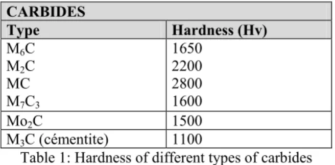
In the HSS quality based on high carbon, medium chromium content and addition of strong carbides forming elements like Mo, W, V, different types of carbides can be founded: MC, M2C, M6C, M7C3.
Table 1 gives the hardness of those carbides. Good wear resistance must be achieved with an adequate combination of them. CARBIDES Type Hardness (Hv) M6C M2C MC M7C3 1650 2200 2800 1600 Mo2C 1500 M3C (cémentite) 1100
Table 1: Hardness of different types of carbides
This microstructure optimisation was focused on the main requirements needed for developing a new grade: - High wear resistance
- Low friction coefficient
- Good resistance to rolling incidents - Good oxidation and thermal behaviour.
For HSS development, the main purpose is to optimise the amount of very hard MC carbides, M7C3 and M2C,
which can be refined and dispersed. Precipitation of the low hardness and brittle M3C carbides is avoided. To
obtain the desired amount and morphology of those carbides, Marichal Ketin uses Vanadium, Tungsten and Molybdenum (2).
A. Metallurgical factors determining wear resistance
When using those rolls, it was found that the wear resistance of the roll for hot rolling was significantly improved by the VC type fine granular carbides, which dispersed uniformly in the matrix while the other metallurgical factors had little effect (4).
Unfortunately, consideration of the solidification process in centrifugally cast roll indicates that in the case of the centrifugal cast roll, VC carbides with a small specific gravity segregate in the inner surface side of the equiaxed grain region owing to the centrifugal force. This phenomenon can be explained in terms of the difference in specific gravity between the primary crystal and the residual molten steel (4). To prevent this carbide segregation, it is necessary to decrease this difference by adjusting the composition.
The MC precipitation temperature rises with increasing vanadium content but the eutectic temperature is practically constant (8). As the vanadium content is decreased, that ∆T decreases and moreover the MC carbides becomes correspondingly finer (8). A lower Vanadium content will give finer carbides arising at lower temperature and leading to smaller segregation.
B. Metallurgical factors determining friction coefficient
Experimental results show that the friction coefficient of a set of HSS rolls type I is above 0.5, which is twice the friction coefficient of Hi-Cr iron rolls (6).
Theses HSS rolls of the first type contain large amount of primary VC carbides embedded in a tempered martensitic matrix. These VC carbides have a high hardness (3000 HV) so they induce good wear resistance. Unfortunately, the surrounding matrix hardness is between 500 and 1000HV, and its wear resistance is weak compared to that of VC carbides. The matrix is worn and the hard carbides project the roll surface, where they act as "spikes" making scratches on the roll matrix. A higher friction coefficient was then observed (6).
To decrease the friction coefficient of the HSS rolls, the hardness difference between the carbides and the matrix must be lowered. To reach this target, either the matrix hardness may be increased or softer carbides may be used.
The effect of additional 5 % cobalt on the properties of HSS alloy has also been investigated (7). It was found that the strength parameters are not improved by cobalt. Hot hardness above 400°C was however found slightly higher, which certainly induces lower wear. Consequently cobalt has probably hindered the wear of the matrix, and therefore decreases the friction coefficient. However, cobalt is very expensive, and its price is volatile on the international market (6).
In order to suppress the micro-sized scratches, the amount of VC carbides must be limited. The use of softer carbides like M2C and M7C3 can decrease the friction coefficient, especially the M2C that can keep high wear
resistance due to its high hardness necessary to compensate the decrease of the amount of VC carbides (3). C. Metallurgical factors determining the good resistance to rolling incident.
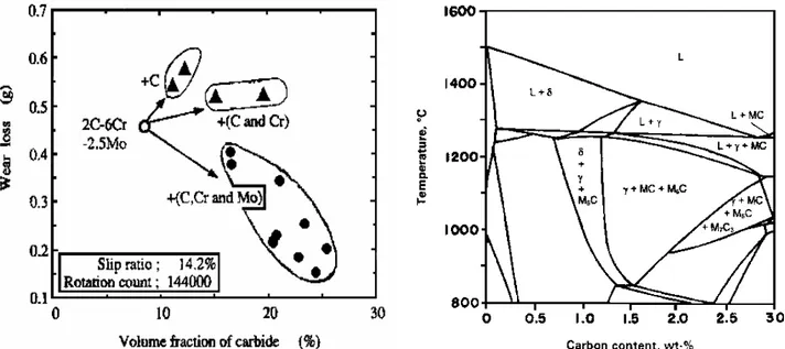
Moreover, in order to make the roll surface smooth during hot rolling, an increasing number of eutectic carbides M2C and M7C3 hard but not so hard as MC is needed. It was proved that the addition of suitable amounts of Cr
and Mo improve the toughness of carbides as seen in figure 1 (4). Rolls having such tough carbides combined with suitable amounts of Cr and Mo are expected to provide higher wear resistance than ordinary HSS rolls (4). On the other hand, the amount of M2C carbides need to be limited to prevent the forming of networks of brittle
particles which could increase sensitivity to crack propagation and reduce spalling resistance in case of rolling mill incidents (5).
It has been shown that the HSS rolls containing high amount of Mo and W have a poorer spalling resistance than Hi-Cr iron rolls. The study of cracks formation in these rolls shows that the cracks follow the eutectic M2Ccarbides. These hexagonal rods like carbides are too brittle, so they are easily split by the crack (6). This
observation led to the reduction in the amount of eutectic M2C carbides in the structure by a reduction in the
Molybdenum and Tungsten content.
D. Metallurgical factors determining oxide film formation
Kinetics of the oxide film formation and its adherence to the roll surface differed greatly between the HSS roll grades and Hi-Cr grades as shown in table 2 (2).
Oxidation behaviour Roll Type
Oxidation kinetics Oxide adherence Hi-Cr Iron with high amount of M7C3 Weak to Low Very good to very high
HSS3 with high amount of MC and M2C carbidesand low amount of M7C3
Very good to very high Weak to Low Standard HSS4 with high amount of
MC, maximized M2C and low amount
of M7C3
Good to very good Weak HSS5 with high amount of MC and
M2C carbides with increased Cr
content
Good Good
Table 2: Roll oxidation performance characteristics (2).
Three types of HSS was studied. The HSS3 rolls shows the fastest oxide formation but the least adherence to the roll surface. The HSS4 rolls shows a slower oxide formation which was more adherent to the roll surface. The HSS5 shows the slowest oxide formation but the best adherence to the roll surface (2). This indicates that the amount of chromium content is an important factor.
3. OPTIMISATION OF HSS ROLLS.
In many mills, the poor reaction to incidents of the HSS remains today an important obstacle to a more intensive use. The roll maker must optimise more the structure of the metal according to the great influence of carbides morphology, the cohesion between the matrix and carbides and the types of carbides found in the spreading of cracks. Even here, the chemical composition and the choice of a more appropriate heat treatment will contribute to a reduction in these risks.
Hence Marichal Ketin developed a suitable grade that gives the best compromise between a low friction coefficient and a high crack propagation and wear resistance. The choice of the composition is based on the considerations developed in the previous chapter.
The microstructure of this HSS grade named HSS7 is based on hard well dispersed primary and eutectic carbides embedded in a tough tempered martensite matrix. This latest grade is achieved to give promising results in several hot strip mills.
4. HSS7 ROLLS CHARACTERISATION.
The composition of HSS7 rolls is shown in table 3. In addition to classical alloying elements (C, Cr, Mn, Si, Ni), it contains Vanadium, Molybdenum and Tungsten.
C Cr Mo V W
1.5-2 5.0-7.0 3.0-4.0 4.0-5.0 1.5-2.5
Table 3: Composition of HSS7
The samples analysed correspond to industrial conditions: the rolls were manufactured by centrifugal vertical spin casting process and a double tempering heat treatment was realised. Samples were then cut off from the roll to obtain samples corresponding to different depths of the working layer of the roll. They were used for microstructure characterisation and mechanical testing.
The characterisation of the microstructure was done using various techniques: -Differential thermal analysis for solidification sequence
-Optical and electron scanning microscopy to determine the analysis of carbides -Image analysis to quantify the volume fraction of carbides and the grain size And some correlations were made with corresponding mechanical properties.
Figure 1: Relationship between Volume fraction of carbides and Wear Loss (4)
Figure 2: Isopleth Fe-5Cr-5W-5Mo-5V-C (wt-%) calculated using Thermocalc (1)
5. SOLIDIFICATION SEQUENCE OF HSS7.
The alloy design of High Speed Steels for rolls is based on the composition of the M2 steel, the main changes being the higher carbon and vanadium contents. Thus, though the roll makers have developed alloys specifically designed to the operational conditions of each hot strip mill plant, their chemical compositions often fall into the following ranges: 1.5-2.0 C; up to 5 % W; up to 5 % Mo; 3-7 % Cr, and 4-8 % V which is the case for the alloy studied here.
Figure 2 shows the calculated isopleths Fe-5Cr-5W-5Mo-5V-C (wt-%), a typical diagram for this composition. It shows that the solidification sequence is rather complex and needs some investigations.
Some studies have done on the solidification of the HSS7. The differential thermal analysis technique (DTA) was used to investigate the solidification sequence and especially the carbides precipitation. Differential thermal analysis (DTA) is a technique in which the sample is heated (or cooled) following a temperature schedule and which can detect any endothermic or exothermic type transformation. Any phase change leads to variations in the sample temperature. The difference in temperature between the sample and the programmed temperature is monitored against time. With the DTA method, any transformation even the small one, can be detected (fusion, solidification, decomposition...).
The figure 3 and 4 illustrate the curve obtained during heating and cooling modes. For carbon between 1.7 and 2.0 %, the solidification sequence can be described by the following reactions:
1) Primary crystallisation of austenite
2) Eutectic decomposition of the residual interdendritic liquid: liquid →austenite + carbides; this reaction moves down a eutectic trough with continuously changing phase compositions, so as to form different eutectic carbides according to the decreasing temperature.
The residual interdendritic liquid decomposes through different eutectic reactions as it moves down a eutectic trough, leading to the formation of up to three eutectics: γ + MC, γ + M6C or γ + M2C and γ + M7C3. Although
the isopleths in Fig. 2 predicts the formation of the γ + M6C eutectic, this eutectic seldom forms since the
solidification normally occurs under non-equilibrium conditions and the formation of the metastable γ + M2C
eutectic is favoured. The γ + MC eutectic always precipitates first, owing to the high vanadium content of these alloys. The sequence by which γ + M2C and γ + M7C3 precipitate depends on the overall chemical composition,
the former being favoured by high W, Mo or V contents and the latter by high Cr or C contents.
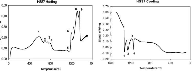
In our ATD experiments, we observed different peaks at high temperatures as described in tables 4 and 5 and figures 3 and 4.
The experimental conditions were: heating from the room up to 1500°C with a 10°C/min rate, and cooling from 1500°C down to room temperature at 10°C/min.
Beginning Peak maximum End
1 387 582 655 2 670 699 728 3 739 749 763 4 772 792 851 5 1065 1105 1139 6 1184 1196 1201 7 1201 1206 1218 8 1249 1314 1330 9 1337 1354 1368
Table 4: Temperatures of peak transformation in HSS7 during heating
Beginning Peak maximum End
1 1337 1329 1314
2 1283 1260 1275
3 1164 1160 1159
4 1159 1152 1141
Table 5: Temperatures of peak transformation in HSS7 during cooling HSS7 Heating 0,00 0,10 0,20 0,30 0,40 0,50 0 400 800 1200 1600 Température °C S ig n a l m W /m g 1 2 34 5 6 7 8 9 HSS7 Cooling -0,20 -0,10 0,00 0,10 0,20 0,30 0,40 0,50 0,60 0,70 0 400 800 1200 1600 Température °C S ig n a l m W /m g 1 2 3 4
Figure 3: DTA curve during heating Figure 4: DTA curve during cooling During heating, we have the reverse austenitic transformation (peaks 1,2,3,4), the dissolution of the carbides M23C6 formed in the tempered matrix (peak 5), the dissolution of the eutectics carbides (peaks 6,7,8) and fusion
of austenitic matrix (peak 9). During cooling, due to cooling rate, we observed only the solidification peak of the austenite (peak 1) and the peaks corresponding to eutectics reactions (peaks 2,3,4).
The eutectic reaction with MC (peak 8 on heating and peak 2 on cooling) is well defined. The two peaks corresponding to γ + M2C and γ + M7C3 are overlapping: it is difficult to separate them. But due to the fact that
the volume fraction of M2C is lower than that of M7C3 as it will be shown latter, we can assume that peak 7 on
heating and related peak 3 on cooling correspond to the transformation of eutectic γ + M2C; the peak 6 on
heating and related peak 4 on cooling correspond to the transformation of eutectic γ + M7C3.
6. CARBIDES IN HSS7
The HSS7 microstructure contains a matrix with the products of austenite decomposition (tempered martensite); globular secondary carbides precipitated in the matrix and eutectic carbides distributed both in the interdendritic or intercellular region.
The nature and morphology of the carbides are influenced by chemical composition. In conventional High Speed Steels, MC carbide dissolves mainly Vanadium. M2C carbides are rich in Molybdenum and Tungsten and can
dissolve Chromium, M7C3 are rich in Chromium.
4
The characterisation of carbides that precipitated in the HSS7 indicates the presence of MC, M6C, M2C and
M7C3. The identification of carbides was made using optical microscopy with selective etching and electron
microscopy (SEM) with EDAX microanalyses.
Figure 5: Cluster of M7C3, M2C and MC Figure 6: EDX on figure 5
Five types of carbides were founded after SEM/EDX analyses: MC, M2C, M7C3, M6C, and M23C6. MC, M2C,
M7C3, M6C are eutectic carbides, which means that they precipitate from the liquid. MC is V-rich and its
morphology is often globular. M2C is Mo/W-rich, with an acicular shape (Cluster of rod-like particles). M7C3 are
Cr-rich, and they are located at grains boundaries and distributed as a continuous network. M6C are Fe/Mo-rich,
and they appear to be located only on the first five millimetres of the shell (higher cooling rates), whereas others carbides types are present on the full shell thickness. M23C6 are Cr-rich fine secondary carbides fully dispersed
within the matrix. Hence, M23C6 appear during tempering.
In HSS7 we found both divorced and complex regular MC carbides. Figures 5 and 7 illustrate the microstructure. MC carbides are present in the full shell thickness of the roll. Their shape is globular; they form clusters inside the matrix, or they are associated to M7C3 carbides in the interdendric region. These MC carbides
are rich in vanadium but dissolve Cr, Mo, a little W and very few Fe elements as shown in the EDAX mapping of Figure 6.
M7C3 carbides are also present in the full shell thickness of the roll. They possess a complex fan-shaped
morphology. M7C3 are rich in Cr but dissolve also Mo, V, a little Fe and very few W as shown in the EDAX
mapping of Figure 8.
M23C6 M
C
CC
M7C3Mo (L
αααα
)
V (K
αααα
)
Cr (K
αααα
)
Fe (K
αααα
)
W (M
αααα
)
Mo (L
αααα
)
V (K
αααα
)
Cr (K
ββββ
)
Mn (K
αααα
) Fe (K
αααα
) Ni (K
αααα
)
Most of M2C carbides possess an acicular form as shown in Figure 7 where they appear light. They are generally
associated to M7C3 and MC. M2C carbides are rich in Mo and dissolve W and V but very few Fe as shown in the
EDAX mapping of Figure 8.
Complex clusters of carbides could give an idea on the precipitation sequence of carbides. BSE (backscattered electron image) have been used for further analyses on carbides. In fact, variation in the BSE contrast of MC carbides is the result of chemical segregations related to solidification sequence. MCs that are located at the top of cluster ends appear to be the first eutectic carbide to precipitate. As the solidification goes ahead, the V content of the residual liquid is lowered, and that allows others carbides types such as M7C3, to precipitate in the
cluster centre (Fig.9). Here we observed the presence of M6C carbides since the analysed zone is close to the
surface (5 mm depth inside the shell). It must be pointed that in the industrial roll the first 10mm of the as-cast roll are removed before putting the roll in operation. These M6C are not present during mill operation.
Figure 9: Cluster of carbides (BSE Image)
DENSITY OF CARBIDES
The total volume fraction of eutectic carbides and the volume fraction of each eutectic carbide depend mainly on the chemical composition, the effect of the cooling rate being less significant (1). The total volume fraction of eutectic carbides in High Speed Steels for rolls ranges from 9% to more than 15%, which is one of their main characteristics (1).
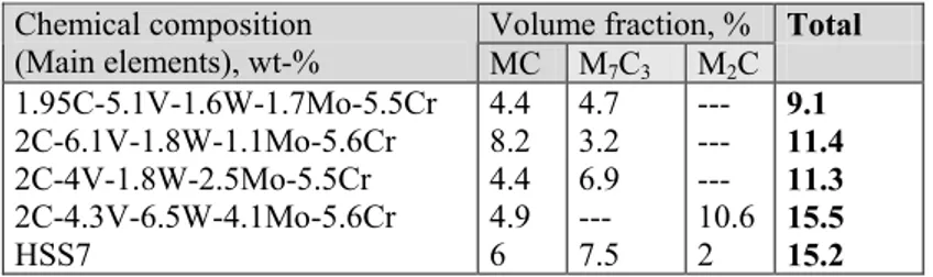
Table 6 gives the volume fraction of the MC, M7C3 and M2C eutectic carbides in HSS7 as obtained in our image
analysis study compared to other high speed steels for rolls (1). The total volume fraction of HSS7 carbides equals to 15%.
Volume fraction, % Total Chemical composition (Main elements), wt-% MC M7C3 M2C 1.95C-5.1V-1.6W-1.7Mo-5.5Cr 2C-6.1V-1.8W-1.1Mo-5.6Cr 2C-4V-1.8W-2.5Mo-5.5Cr 2C-4.3V-6.5W-4.1Mo-5.6Cr HSS7 4.4 8.2 4.4 4.9 6 4.7 3.2 6.9 --- 7.5 --- --- --- 10.6 2 9.1 11.4 11.3 15.5 15.2
Table 6: Volume fractions of MC, M7C3 and M2C eutectic carbides in High Speed Steels for rolling mill rolls
DENDRITE SPACING
The as-cast dendrite microstructure is defined in a quantitative basis by the primary and secondary dendrite spacing, the latter being more widely used as a parameter for correlating process variables and microstructure, since the primary dendrite spacing intervenes only in the case of directional solidification.
The effects of the liquid phase thermal gradient, dendrite growth rate, and coarsening/coalescence phenomena on the secondary dendrite arm spacing (simply designated hereafter as the dendrite arm spacing, DAS) have been well characterised experimentally (1).
M7C3
M6C
MC
It is generally admitted that the effects of the liquid phase thermal gradient G and dendrite growth rate V (which are independently controlled in directional solidification experiments) on the DAS are related by an empirical relationship where both variables are lumped into one single parameter, namely the cooling rate, as dT/dt = GV
DAS = A(dT/dt)-b
where A and b are material-specific parameters. Figure 10 shows experimental curves, DAS versus DT/dt for M2 (1). In the MK Spin Casting Process, a cooling rate ranging from 5 and 10°C/min is observed, leading to an average DAS around 23 to 35µm.
Figure 10 (1)
Figure 11: Grain Size in depth
In HSS7, solidification is equiaxed from the surface to a depth of 10mm of the shell. Then the solidification becomes columnar till the bonding zone between shell and core. Nevertheless one can observed, near that bonding zone, areas where columnar zone are mixed to equiaxed zone.
Carbides are distributed in the interdendritic space. In the columnar region, carbides are aligned along the dendrites arms with a majority of MC carbides. MC carbides are aligned and they converge on the M7C3 carbides
that are positioned as final central nodules (Figure 9).
Grain size measurement is also obtained from Image Analysis. The M7C3 carbides network outlines grains
boundaries. As a result, we found that there is an increase of the grain size from the shell (50 µm) to the core (70 to 100 µm) (Figure 11).
MECHANICAL PROPERTIES
Figures 12 and 13 indicate the properties of HHS7 compared to Hi-Cr. The samples were taken at different locations from the outer part of the shell to the bonding zone between shell and core to study the evolution of those properties through the working layer of the roll.
Mechanical properties of HHS7 are better than those of Hi-Cr. The decrease in tensile strength in the shell depth is to be related to the corresponding increase of the grain size. Nevertheless at the roll end of life the mechanical properties are still comparable to Hi-Cr (Figure 13).
Figure 12 gives the average hardness of HSS7 compared to Hi-Cr. Both of them show no hardness decrease in depth, whereas HSS7 hardness is always above Hi-Cr one.
150 250 350 450 550 650 750 0 10 20 30 40 50 60 70 80
Distance to roll surface (mm)
H ar dn es s ( H V )
Start of the roll life End of the roll life
Hi- Cr
Tensile Strength in depth
0 200 400 600 800 1000 1200 0 10 20 30 40 50
Distance to the roll surface (mm)
T e n si le st re n g th ( M p a ) Hi Cr
Start of the roll life End of the roll life
Figure 12: Hardness in depth (Hi-Cr/HSS) Figure 13: Tensile Strength in depth (Hi-Cr/HSS) Dendrite Arm Spacing (DAS) versus dT/dt
0 ,1 1 1 0 1 0 0 D T/ dt ( K/ s e c ) DA S ( µm ) 5 10 25 50 75 100 125 0 10 20 30 40 50 60 70 Shell depth (mm) In te rc ep t L en gt h ( µ m )
CONCLUSIONS
A recent development makes use of cast highly alloyed high speed steels are the material for the outer shell of centrifugally cast or continuously poured composite (CPC) Hot Strip Mill rolls. These materials were developed with compositions near that of M2 tool steel, but with higher carbon and vanadium contents. For carbon levels between 1.7 % and 2.0 %, their solidification sequence can be described by the following reactions: (a) primary crystallisation of austenite; (b) eutectic decomposition of residual interdendritic liquid, leading to the formation of up to three eutectics: γ + MC; γ + M6C or γ + M2C; and γ + M7C3. The total volume fraction of eutectic
carbides in high speed steels designed for rolls ranges from 9 % to more than 15 %, which is one of their main characteristics. However, some Japanese publications mention carbides content higher than 20%.
HSS7 was developed on this basis with emphasis on optimisation of carbides proportion. For HSS improvement, the main purpose is to optimise the amount of MC (very hard) carbides, M7C3 and M2C that can be refined and
dispersed. To obtain the optimised amount and morphology of carbides Marichal Ketin uses Vanadium, Tungsten and Molybdenum (2).
Marichal Ketin developed a suitable grade that gives a good compromise between a low friction coefficient and high crack propagation and wear resistance.
The microstructure of this HSS grade is based on hard well dispersed primary and eutectic carbides embedded in a tough tempered martensitc matrix. This latest grade is achieved to give promising results in several Hot Strip Mills. HSS rolls containing mainly hard MC carbides have a high friction coefficient, which is detrimental for the rolling power consumption and for the strip surface quality. On the other hand, HSS rolls containing eutectic rod shaped carbides are brittle and more susceptible to spalling. To overcome these problems, a roll with well-dispersed hard carbides, and non-interconnected eutectic carbides has been developed. This alloy contains small VC carbides improving wear resistance, and well dispersed eutectic carbides. These eutectic carbides are a mixture of M2C and M7C3, hindering crack propagation.
The total volume fraction of carbides in HSS7 is around 15%.
BIBLIOGRAPHY
(1) M. Boccalini and H. Goldstein,” Solidification of high speed steel”, International Materials Reviews, 2001, Vol.46, N°2,p.92.
(2) R.J. Sckoczinsky, “High speed steel roll trials and their performance at Iscor”, Saruc 96 p. 31.
(3) T. Hattori et al, new high Speed Steel Rolls for Hot Strip Mills, 7th International Conference on Steel Rolling, 1998, Chiba, Japan.
(4) K. Ichino et al, Development of Centrifugal Cast Roll with High Wear Resistance for Finishing Stands of Hot Strip Mill, Kawasaki Steel Technical Report, N°37, October 1997.
(5) R.J. Sckoczinsky et al, Improvement of the Work Roll performance on 2050 mm hot Strip Mill at Iscor Vanderbijlpark, 42nd MWSP Conf. Proc., ISS, 2000.
(6) J. P. Breyer et al, Off-line Analysis of the HSS roll Behaviour in the Hot Strip Mill by the Use of a Rolling Load Prediction Model, SARUC 97 p.19.
(7) J.Lecomte-Beckers, L.Terziev
report of scientific cooperation between Bulgaria and community Wallony-Bruxelles and Walloon Region( DRI) “study of precipitation cinetic in foundry alloy for rolls type chromium iron and HSS” – 2002.