SHERBROOKE
Faculte de genie
Departement de genie civil
Developpement et performance des
betons autopla^ants fibres pour les
applications de reparation
(Development and performance of fiber-
reinforced self-consolidating concrete for repair
applications)
These de doctorat es sciences appliquees
Speciality: genie civil
Fodhil KASSIMI
1+1
Published Heritage Branch Direction du Patrimoine de I'edition 395 Wellington Street Ottawa ON K 1A0N 4 Canada 395, rue Wellington Ottawa ON K1A 0N4 CanadaYour file Votre reference ISBN: 978-0-499-00403-1 Our file Notre reference ISBN: 978-0-499-00403-1
NOTICE:
The author has granted a non
exclusive license allowing Library and Archives Canada to reproduce, publish, archive, preserve, conserve, communicate to the public by
telecomm unication or on the Internet, loan, distrbute and sell theses
worldwide, for commercial or non commercial purposes, in microform, paper, electronic and/or any other formats.
AVIS:
L'auteur a accorde une licence non exclusive permettant a la Bibliotheque et Archives Canada de reproduire, publier, archiver, sauvegarder, conserver, transmettre au public par telecomm unication ou par I'lnternet, preter, distribuer et vendre des theses partout dans le monde, a des fins com merciales ou autres, sur support microforme, papier, electronique et/ou autres formats.
The author retains copyright ownership and moral rights in this thesis. Neither the thesis nor substantial extracts from it may be printed or otherwise reproduced without the author's permission.
L'auteur conserve la propriete du droit d'auteur et des droits moraux qui protege cette these. Ni la these ni des extraits substantiels de celle-ci ne doivent etre imprimes ou autrement
reproduits sans son autorisation.
In compliance with the Canadian Privacy A ct some supporting forms may have been removed from this thesis.
W hile these forms may be included in the document page count, their removal does not represent any loss of content from the thesis.
Conform em ent a la loi canadienne sur la protection de la vie privee, quelques
form ulaires secondaires ont ete enleves de cette these.
Bien que ces form ulaires aient inclus dans la pagination, il n'y aura aucun contenu manquant.
The use o f self-consolidating concrete (SCC) in the concrete industry in cast-in-place applications, including repair applications, is grow ing given the various advantages offered in both fresh and hardened states. The present study deals with the design and perform ance o f fiber-reinforced self-consolidating concrete (FR-SCC) as a repair material o f concrete infrastructure. The study also considers the use o f various steel and synthetic fibers (five fibers in total) that were used to produce FR-SCC and fiber-reinforced self-consolidating m ortar (FR-SCM ) that can be em ployed for structural and non-structural repair applications. The study evaluates the effect o f material properties and m ixture com position o f the fibrous concrete and m ortar on w orkability, m echanical, visco-elastic, durability, and structural behavior. The investigation that is presented in this thesis included the testing o f 28 full-scale beam s under four-point flexural loading. The m ajority o f these beam s were repaired by casting concrete to fill a relatively thin section along the tension zone o f the beams. The repair technique w as based on the FR-SCC characteristics including the m axim um fiber volum e and length. This technique required m ixtures o f high range o f fluidity. The optim ized FR-SCC and FR-SCM m ixtures exhibited excellent flow characteristics along the 3.2-m long beam s w ithout blockage, segregation, nor debonding at the interface o f repair-substrate concrete. Based on the structural characteristics o f the com posite beams, the overall perform ance o f the beam s repaired using the FR-SCC and FR-SCM w as sim ilar or higher (up to 2.6 tim es) than that o f m onolithic beam s m ade w ith conventional vibrated concrete (CVC). The use o f optim ized FR- SCC m ixtures enabled the replacem ent o f 50% o f the tension steel reinforcem ent in repair sections; i.e., the num ber o f bars in the tension zone decreased from three bars to two bars with the addition o f fibers in the SCC w ithout m itigating structural perform ance. The degree o f prediction o f crack width, cracking load/m om ent, ultimate loads, and deflection o f various FR-SCC and FR-SCM m ixture was evaluated using several design and code models. The results indicate that these code m odels can provide safe predictions for crack and ultim ate loads, as well as crack w idth o f FR-SCC. The deflection o f FR-SCC is unsafe but predictable by these code models.
In total, 18 large-scale beams w ere tested in four-point for flexural creep. FR-SCC incorporating steel fibers com bined w ith expansive agent provided overall perform ance up to
constant load w as reduced by 60% to 80% using self-consolidating fibrous m ixtures made w ith or w ithout expansion agents, com pared to SCC w ithout fibers.
The best com bination to reduce the cracking potential when the restrained shrinkage ring test w as em ployed w as obtained with SCC m ixtures m ade with steel fibers and expansive agent. M odels were elaborated to predict the tim e-to-cracking for FR-SCC and FR-SCM m ixtures based on m ixture modulus o f elasticity and drying and autogenous shrinkages.
The project involved extensive testing o f highly flowable fibrous m aterials to determ ine drying shrinkage (nearly 260 prisms), m odulus o f rupture (nearly 180 prism s), as well as com pressive and splitting tensile strengths and elastic modulus (nearly 2100 cylinders). Based on the results, m odels were proposed to predict these key material properties that affect the perform ance o f FR-SCC and FR-SCM used in repair applications.
In addition to FR-SCC, the investigation also w as set to evaluate the feasibility o f using fiber- reinforced superw orkable concrete (FR-SW C) in construction and repair applications. Such highly flow able concrete that requires lim ited vibration consolidation can represent some advantages over FR-SCC (lower adm ixtures dem and, low er risk o f segregation, greater robustness, low er form w ork pressure, etc.). The energy needed to ensure proper consolidation, using either vibration or rodding, applied on sam ples m ade with FR-SW C w as determined. The energy requirem ent took into consideration the developm ent o f m echanical properties, the resistance to segregation, and the developm ent o f proper surface quality. The study also dem onstrated the higher overall structural perform ance o f optim ized FR-SW C com pared to the corresponding FR-SCC mixtures.
The findings o f the thesis on the design and perform ance o f highly w orkable fiber-reinforced cem entitious m aterials should facilitate the acceptance o f such novel high-perform ance material in infrastructure construction and repair applications.
Keywords:
Beam, blockage, consolidation, concrete, construction, cracking, flexural creep, fibers, rehabilitation, repair, restrained shrinkage, rheology, segregation, self-consolidating concrete, self-consolidating mortar, superw orkable concrete, viscosity, workability.
L ’utilisation du beton autopla9ant (BAP) dans l’industrie du beton dans les applications du
coulage sur place incluant les applications de la reparation, est en croissance vu les divers avantages offerts a l’etat frais et a l’etat durci. La presente etude traite de la conception et la perform ance des betons autopla9ants fibres (BA PF) en tant que m ateriau de reparation des
infrastructures en beton. L ’etude considere egalem ent l’usage de differentes fibres m etalliques et synthetiques (cinq fibres au total) qui ont ete utilisees pour produire des BAPF et des mortiers autopla9ants fibres (M APF) pour des applications de reparations structurales et non
structurales. L ’etude evalue l’effet des proprietes du materiau et la com position des betons et mortiers fibres sur l’ouvrabilite, les proprietes m ecaniques, viscoelastiques, de durability et le com portem ent structural. L ’etude presentee dans cette these a inclus 28 poutres a grande echelle testees sous un chargem ent flexionnel a quatre points. La m ajorite de ces poutres a ete reparee par le coulage du beton pour rem plir une section relativem ent m ince tout au long de la zone tendue des poutres. La technique de reparation a ete basee sur les caracteristiques des BAPF incluant le volum e m aximal et la longueur m axim ale de fibres. Cette technique a requis des melanges de haut niveau de fluidite. Les BAPF et M APF ont exhibe d ’excellentes caracteristiques d ’ecoulem ent le long de 3,2 m, la longueur de la poutre, sans blocage, segregation, ni decollem ent a 1’interface entre le beton de base et le beton de reparation. En se basant sur les caracteristiques structurales des poutres com posites, la perform ance globale des poutres reparees en utilisant les BAPF et les M APF etait sim ilaire ou superieure (jusqu’a 2,6 fois) que celle des poutres m onolithiques fabriquees d ’un beton conventionnel vibre (BCV). L ’utilisation des m elanges de BAPF optim ises a perm is de rem placer 50% du ferraillage tendu dans les sections de reparation; c ’est-a-dire que le nom bre des barres d ’arm atures dans la zone tendue a reduit de trois barres a deux barres avec l’addition de fibres dans le BAP sans m itiger la perform ance structurale. Le degre de prediction de la largeur de fissures, charge de fissuration, charge ultime et deflexion de differents melanges de BAPF et M APF a ete evalue en utilisant quelques designs et modeles de codes. Les resultats ont m ontre que ces m odeles ont pu foum ir de predictions securitaires pour les charges de fissuration et ultim e, ainsi que la fissuration des BAPF. La deflexion des BAPF est non securitaire m ais reste predictible par ces modeles de codes.
BAPF contenant des fibres m etalliques com binees avec un agent expansif ont foum i une perform ance globale ju sq u ’a 10 fois celle obtenue avec un BCV contenant le meme type et volum e de fibres. La fissuration sous une charge constante a ete reduite de 60% a 80% en utilisant des m elanges autoplasants fibres fabriques avec ou sans agents expansifs, par rapport au BAP sans fibres.
La m eilleure com binaison pour reduire le potentiel de fissuration avec l’essai du retrait restreint a ete obtenue avec des m elanges de BAP contenant de fibres d ’acier et un agent expansif. Des m odeles ont ete elabores pour predire le tem ps de fissuration des m elanges de BAPF et M APF bases sur le module d ’elasticite du melange et les retraits de sechage et endogene.
Le projet com portait de nom breux essais sur les melanges fibres de haute fluidite a savoir la determ ination du retrait de sechage (pres de 260 prismes), le m odule de rupture (pres de 180 prism es), ainsi que la resistance en com pression, la resistance en traction et le m odule d ’elasticite (plus de 2100 cylindres). En se basant sur les resultats, des m odeles ont ete proposes pour predire ces proprietes cles qui affectent la perform ance des BAPF et M APF destines aux applications de reparation.
En plus des BAPF, l’etude a aussi ete faite pour evaluer la faisabilite de l’utilisation des betons sem i-fluides fibres (BSFF) dans les applications de construction et de reparation. Tels betons de haute fluidite requerant une consolidation lim itee peuvent presenter certains avantages par rapport aux BAPF (plus faible dem ande en adjuvants, plus faible risque de segregation, robustesse superieure, plus faible pression sur les coffrages, etc.). L ’energie necessaire pour assurer une propre consolidation, en utilisant soit la vibration ou le piquage, appliquee sur des echantillons de BSFF a ete determinee. Les exigences de cette energie considerent le developpem ent des proprietes m ecaniques, la resistance a la segregation et la propre qualite de surface. L ’etude a aussi dem ontre une perform ance structurale globale superieure des BSFF optim ises par rapport aux melanges de BAPF correspondant.
Les conclusions de la these sur le design et la perform ance des m ateriaux cim entaires renforces de fibres et de haute fluidite devraient faciliter l’acceptation de tels nouveaux
infrastructures.
Mots cles:
Beton, beton autoplafant, beton semi-fluide, blocage, consolidation, construction, fibres, fissuration, fluage flexionnel, mortier autopla5ant, ouvrabilite, poutre, rehabilitation,
First of all, praise to God, Lord o f the Worlds for giving me the power and patience to accomplish this challenging project.
The author has been working for his Ph.D. since 2008 on development o f fiber-reinforced self- consolidating concrete and mortar for repair applications and evaluation o f their performance in fresh and hardened states. This work was a continuation o f the M.Sc. project.
The author would like to thank gratefully Professor Kamal Khayat for his high-quality supervision, guidance, advices, help, kindness, and availability, leading to a successful work that required considerable physical and moral energies and financial support. His corrections that enhanced the quality of the thesis and papers are appreciated.
The author also wishes to acknowledge the Universite de Sherbrooke and the NSERC as well as the 19 industrial partners participating in funding the program o f the Industrial Research Chair on “High-Performance Flowable Concrete with Adapted Rheology”, managed by Professor Kamal Khayat. This thesis was a part o f the first phase of this chair undertaken between 2008 and 2013. The chair partners were: Canadian Cement Association (Ciment Quebec, Lafarge Canada, and St-Lawrence Cement), Euclid Canada, exp, Grace, Groupe SM International, Handy Chemicals, Holcim, Hydro-Quebec, Inspec-sol, Laboratoires ABS, Laboratoires Shermont, LVM-Technisol, Ministere des Transports du Quebec, Omya Canada, Qualitas, Saramac, Sika Canada, SNC-Lavalin, and Ville de Montreal. The author thanks BASF, Bekaert, and Propex Concrete Systems for their supply o f materials for this projet. The author is greatly thankful to the members of dissertation committes, including Professors Ammar Yahia, Radhouane Masmoudi, and Liberato Ferrara for their availability and acceptation to evaluate this work in a short time. Special thanks go to Professors Habib Mesbah, Parviz Goddousi, Ammar Yahia, and Ahmed El-Sayed for their contribution in putting the cornerstone o f this project. Professor Ammar and Soo-Duck Hwang are also acknowledged for their comments and corrections.
The author is grateful to all professors, research assistants (including Ahmed Omran and Olivier Bonneau), post-docs (including Ahmed Farghali), technicians (including Denis Bolduc,
collaborated in this project. The help and kindness of Professor Jean Proulx are acknowledged. This work is decicated to the author’s parents for their countless sacrifices, to his wife for her encouragment, support, and patience, to his beloved daughter, and to his brothers and sisters.
ABSTR AC T ... i
SO M M AIRE... iii
ACKNOW LEDGEM ENT... vii
TABLE OF CONTENTS... ix
LIST OF FIGURES... xviii
LIST OF TABLES...xxv
NOM ENCLATURE... xxix
CHAPTER I INTRODUCTION... 1
1.1 B ack g ro u n d ... 1
1.2 O b jectiv es... 3
1.3 O rganization o f thesis...4
CHAPTER 2 DEGRADATION AND REPAIR OF CONCRETE... 6
2.1 D urability and degradation o f co n crete...6
2.1.1 Intro du ction...6
2.1.2 Causes o f degradation o f concrete...6
2.1.3 D egradation o f concrete by transport o f flu ids... 7
2.1.4 Effect o f continuity in pore s y s te m ... 8
2.1.5 Perm eability and porosity...8
2.1.6 A ir entrainm ent... 9
2.1.7 Effects on de-icing s a lts ... 9
2.1.8 Concrete pathology... 9
2.1.9 Reinforcem ent co rro sio n ... 10
2.2 Repair o f concrete structures... 12
2.2.1 M ain surface repair m aterials... 13
A) Portland cem ent m o rtar... 13
B) Epoxy m o rtar...13
C) Expansive m ortar and g r o u t... 14
D) Conventional vibrated concrete... 14
E) Latex concrete and m o rta r...14
F) Polym er c o n c re te ...15
G) Conventional concretes w ith epoxy resin-based link la y er... 15
H) Fiber-reinforced co n crete...15
2.2.2 Procedures for repair o f c o n c re te ... 15
A) Use o f pre-slabs as perm anent form works for repair o f bridge s la b s ...16
B) Use o f precast FRC in construction and repair o f p arap ets...17
CHAPTER 3 FIBERS AND SELF-CONSOLIDATING CONCRETE...18
3.1 F ib ers... 18
3.1.1 D efinition, properties, roles, and advantages o f fib ers...18
3.1.2 A pplication are a s...18
3.1.3 Effect o f fibers on fresh properties o f con crete... ... 18
A) Effect o f fiber le n g th ... 22
B) Effect o f fiber aspect ra tio ... 22
C) Effect o f fiber fa c to r... 22
D) Effect o f fiber geo m etry ... 24
E) Effect o f fiber ty p e...25
F) Effect concrete ty p e ...25
G) Fibers-aggregates in teractio n ... 25
H) Effect o f fibers on spacing betw een reinforcing bars... 27
I) Effect o f w /c and adm ixture content on fluidity and stability o f F R -S C C ... 28
J) Effect o f fibers on air volum e o f fresh concrete... 29
K) Effect o f fibers on density o f fresh co n cre te ... 29
3.1.4 Effect o f fibers on hardened p ro p erties... 30
A) Effect o f fiber v o lu m e... 30
B) Effect o f fiber le n g th ... 35
C) Effect o f aspect ratio and fiber g eo m etry ...37
D) Effect o f fiber facto r... 39
E) Effect o f fiber ty p e...40
F) Effect o f m atrix properties... 40
3.1.5 Toughness and average residual stren gth ...41
3.1.6 O rientation and distribution o f fib e rs...42
A) 1 -D o rien tatio n ...45
B) 2-D o rie n ta tio n ...45
C) 3-D o rie n ta tio n ...46
3.2 Self-consolidating co n cre te ...48
3.2.1 Definition, roles and advantages o f S C C ...48
3.2.2 Limits o f acceptance o f SCC for repair ap p licatio n s... 49
3.2.3 Fibers in S C C ... 52
3.2.4 Rheological properties o f FR -SC C ... 52
3.2.5 Fiber-reinforced self-consolidating m o r ta r ... 53
3.2.6 Cost o f FR -SC M ... 53
3.2.7 FR-SCM characterization d evices...54
3.2.8 A pplications and advantages o f F R -S C M ...56
4.1 Intro du ctio n ... 58
4.2 Drying sh rin k ag e... 58
4.2.1 Drying shrinkage and com patibility betw een substrate and repair co n crete... 58
4.2.2 Drying shrinkage for dim ensional com patibility... 58
4.2.3 Prediction m odels o f drying shrinkage... 59
A) A A SH TO LFRD [2007] m odel... 59 B) A C I 209 [1992] m o d e l... 60 C) B3 [1995] m od el... 62 D) CEB-FIP [1990] m o d e l...65 E) GL [2000] m o d e l... 67 F) KL [2010] m o d e l... 68 G) SAKATA [1993] m o d e l...68
4.2.4 W hy m odify drying shrinkage m o d e ls? ... 69
4.2.5 Com parison between m odels...70
4.3 C r e e p ... 72 4.3.1 M odeling o f c r e e p ... 72 A) A ASH TO LRFD [2007] m odel... 72 B) ACI 209R [1992] m o d el... 73 C) CEB-FIP [1990] m o d e l... 73 D) GL [2000] m o del... 74 E) SAKATA [1 99 3]m od el... 75
CHAPTER 5 MATERIALS, MIXTURE PROPORTIONS, MIXING, AND TEST METHODS... 76 5.1 M aterials... 76 5.1.1 A g g reg ate ... 76 5.1.2 C em ent...76 5.1.3 A d m ixtures...78 5.1.4 F ib ers... 79
5.2 M ixture pro po rtioning... 82
5.2.1 Conventional vibrated concrete... 82
5.2.2 Self-consolidating co n cre te... 82
5.2.3 Fiber-reinforced self-consolidating concrete and fiber-reinforced superw orkable c o n c re te ...82
5.2.4 Fiber-reinforced self-consolidating m o r ta r ... 83
5.2.5 A ir entrainm ent in freshly prepared m ix tu re s... 84
5.3 M ixing sequence...84
5.3.1 Conventional vibrated m ix tu re s... 85
5.3.2 Self-consolidating m ixtures... 85
5.4.3 M odified V-funnel te s t...92
5.4.4 M odified L-box te s t...93
5.4.5 Caisson filling capacity te st...93
5.4.6 Rheom eter te s t...94
5.4.7 Surface settlem ent te s t... 95
5.5 Sam pling and co n so lid atio n ...95
5.6 C u rin g ...96
5.6.1 C y lin d e rs... 96
5.6.2 P rism s...96
5.6.3 R ings... 99
5.7 M ixtures nom enclature... 99
CHAPTER 6 MECHANICAL PROPERTIES...100
6.1 In tro du ction... 100
6.2 Typical test results on mechanical properties... 100
6.4 Prediction m odels for mechanical p ro p erties... 104
6.5 Prediction results and d iscu ssio n s...112
6.6 M odification o f existing m odels and proposition o f new prediction m odels for mechanical properties... 119
6.7 C onsideration o f m ixtures with com m on param eters... 122
6.8 C o n clu sio n s...132
CHAPTER 7 DRYING SHRINKAGE... 134
7.1 A b stra c t... 134
7.2 In trod uction ...135
7.3 M aterials and m ixture proportioning... 136
7.4 M ixing and c u rin g ... 137
7.5 Results and discussion... 137
7.6 C o n clu sio n s...145
CHAPTER 8 RESTRAINED SHRINKAGE... 146
8.1 A b stra c t...146
8.2 In tro d u ctio n ...147
8.3 Experim ental pro g ram ... 148
8.4 Experim ental results and discussion... 154
8.4.1 Fresh state... 154
8.4.2 M echanical p ro p e rtie s... 155
8.4.3 V isco-elastic p ro p erties... 155
8.5 Prediction o f tim e-to-cracking...159
8.6 C o n clu sio n s...160
CHAPTER 9 FLEXURAL RESPONSE AND DURABILITY...162
9.1 Intro du ction ...162
9.2 Difficulties and contradictory situ a tio n s... 165
9.3 Design o f beam e le m e n ts ...165
9.4 Beam -rupture m o d e ...168
9.4.1 Beam w ith 2*20M b a r s ... 169
9.4.2 Beam with 3><20M b a r s ... 170
9.5 D iscussion on thickness o f repair la y er...170
9.6 Sim ulation prior to re p a ir ... 171
9.7 General preparation o f beam s...176
9.8 Preparation o f m onolithic beam s... 178
9.8.1 Casting and sam p lin g ... 178
9.8.2 Dem olding and cu rin g ... 179
A) B eam s... 179
B) C y lin d e rs ... 180
C) P rism s... 180
9.9 Preparation o f repaired b eam s...180
9.9.1 Prelim inary p rep aratio n s...180
9.9.2 Casting o f su b strate ...183
9.9.3 Interm ediary preparations, dem olding, and curing o f sub strate... 183
9.9.4 Casting o f re p a ir...185
9.9.5 D em olding and curing o f repaired b e a m s ...187
9.10 Loading and strain-control sy stem s... 188
9.11 Cores for in-situ com pressive stren gth... 193
9.12 Rapid chloride-ion perm eability...194
9.13 M ercury-intrusion p o ro sim e try ... 194
9.14 Drying sh rin k ag e... 195
A) Com pressive stren g th ... 198
B) Cores for com pression...202
C) Splitting tensile strength... 203
D) M odulus o f rupture... 205
E) M odulus o f e la stic ity ...206
9.17.3 D urability... 206
A) P o ro sity ...206
B) Perm eability... 206
9.17.4 V isco-elastic p ro p erties... 207
A) Drying sh rink age...207
9.17.5 Flexural behavior...211
A) Load-deflection resp o n se... 212
B) Crack load... 212
C) Yield lo a d ... 213
D) Ultimate lo a d ...213
E) Reinforcem ent and concrete strain s...217
F) Crack w id th ... 225
G) Cracking p a tte rn ... 231
El) Flexural to u g h n e ss... 237
I) S tiffn e ss...237
J) Debonding at substrate-repair interface... 238
K) Com parison o f overall structural p e rfo rm a n ce... 238
L) Cost-efficiency aspect...245
9.18 C o n clu sio n s...246
9.18.1 W orkability o f concrete... 246
9.18.2 Repair technique...247
9.18.3 M echanical p ro p erties... 247
9.18.4 In-situ com pressive strength... 247
9.18.5 Porosity, RCP, and drying shrinkage o f beam concrete... 248
9.18.6 Structural p ro p erties... 248
9.18.7 Cost efficiency o f beam c o n cre te...249
CHAPTER 10 STRUCTURAL PREDICTIONS IN FLEXURE... 250
10.1 In tro du ction...250
10.2 Prediction o f crack lo ad ... 250
10.2.1 ACI 318 [2011] and C S A A 23.3 [2004] C o d e s...250
10.2.2 ACI 544 [2011] C o d e ...251
10.3 Prediction o f ultim ate lo a d ... 256
10.4 Prediction o f crack w id th ... 259
10.4.1 CSA A23.3 [2004] C o d e ...259
10.7 C o n clu sio n s... 269
10.7.1 Prediction o f crack load... 269
10.7.2 Prediction o f ultim ate lo a d ...269
10.7.3 Prediction o f crack w id th ...269
10.7.4 Prediction o f d eflectio n ... 270
CHAPTER 11 FLEXURAL CREEP AND RELAXATION...271
11.1 Introduction and o b je ctiv e s... 271
11.2 Investigated m ixtures...271
11.3 Casting o f creep beam s... 272
11.4 Test m ethods and sam p lin g ... 274
11.5 C u rin g... 274
11.6 Flexural creep beam testing... 274
11.7 Prelim inary p rep aratio n s... 275
11.7.1 D escription o f creep fra m e s ... 275
11.7.2 Calibration o f fram es...279
11.7.3 Load and strain-control systems for flexural creep te s tin g ... 282
1 1.8 Structural calculation...284
11.9 Procedure for creep and relaxation m easurem ents... 285
11.10 Reference beam s...285
11.11 Test results and d iscu ssio n ... 287
11.11.1 Fresh p ro p erties...287
11.11.2 M echanical properties and drying shrinkage... 288
11.11.3 Flexural creep and rela x atio n ...288
A) D eflection...288
B) Concrete and reinforcem ent strain s...289
C) Crack w id th ... 292
D) Overall perform ance under flexural c re e p ... 293
11.12 Com parison with instantaneous bending test results on reference beam s...295
11.13 Com parison with full-scale beam tests...298
11.14 Com parison w ith ring test resu lts...299
11.15 C o n clu sio n s...300
CHAPTER 12 CONSOLIDATION OF FR-SW C... 302
12.1 A b stra c t... •...303
12.3.1 M aterials...304
12.3.2 Test procedures... 305
12.4 Experim ental results and discussion... 307
12.5 C o n clu sio n s...311
CHAPTER 13 CONCLUSIONS AND RECOMMENDATIONS...314
13.1 General characteristics o f FR-SCC for r e p a ir... 314
13.2 M echanical p ro p e rtie s... 315
13.3 Drying sh rin k ag e...316
13.4 Restrained sh rin k a g e ...316
13.5 R epair tech niq ue...318
13.6 Flexural response and d u rab ility ... 318
13.7 Predictions o f structural p erfo rm an ce... 320
13.8 Flexural c re e p ... 321
13.9 C onsolidation o f F R -S W C ... 322
13.10 Perspectives and recom m endations... 324
CHAPTER 14 CONCLUSIONS ET RECOMMANDATIONS (FR A N C A IS)...326
14.1 Caracteristiques generates des BAPF pour rep aratio n ... 326
14.2 Proprietes m ecaniques... 327
14.3 Retrait de sechage...328
14.4 Retrait restrein t... 329
14.5 Technique de rep aratio n ... 330
14.6 Reponse en flexion et durability... 330
14.7 Predictions structurales... 332
14.8 Fluage flex io nn el...334
14.9 C onsolidation des B S F F ... 335
14.10 Perspectives et recom m andations...337
APPENDIX A DRYING SHRINKAGE... 339
A .l Predicted and m odified shrinkage m odels vs. experim ental shrinkage o f FR -SC C 340 A.2 Predicted and m odified shrinkage m odels vs. experim ental shrinkage o f FR -S C M 343 APPENDIX B RESTRAINED SHRINKAGE...346
APPENDIX D STRUCTURAL PREDICTIONS IN FLEXURE... 351
APPENDIX E CONSOLIDATION OF FR-SW C ...359
REFERENCES... 362
Chapter 1
Fig. 1.1 Diagram o f the thesis o rg an izatio n ...5
Chapter 2 Fig. 2.1 D egradation o f concrete du to alkali-aggregate reaction [KHAYAT, 2 0 0 6 ]... 10
Fig. 2.2 Steel reinforcing corrosion on surface o f wall [KHAYAT, 2 0 0 6 ] ...10
Fig. 2.3 Relative volum e o f iron oxidation products [M ETHA, 20 0 6 ]...11
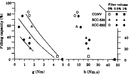
Chapter 3 Fig. 3.1 Com parison o f filling capacity w ith the rheological param eters g et h [K HAYAT et al., 20 00] 20 Fig. 3.2 Effect o f fibers on fresh and hardened properties o f FR-SCC [KHAYAT et al., 2000] 21 Fig. 3.3 Effect o f E/and L /(slum p flow = 600 mm) [G RUN EW A LD et al., 2 0 0 1 ]... 21
Fig. 3.4 Effect o f R I o n (a): slump flow and (b): V-funnel [G RUNEW ALD et al., 2 0 0 1 ]...23
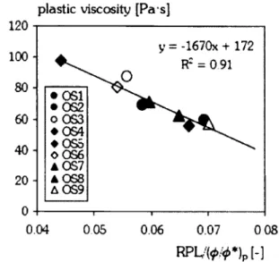
Fig. 3.5 Effect o f the relative paste layer thickness (RPL) on plastic viscosity (PV) [GRUNEW ALD, 2004]... 24
Fig. 3.6 The RPL divided by the norm alized paste content com pared with the PV [GRUN EW A LD , 2004]... 24
Fig. 3.7 Effect o f carbon fiber surface specific on paste [GRUN EW A LD , 2004]...25
Fig. 3.8 Effect o f the aggregate size on the fiber distribution [GRUN EW A LD , 2004 after JO H N STO N , 19 96]...26
Fig. 3.9 Effect o f the coarse aggregate content on the m axim um content o f steel fibers [SW AM Y, 1975]... 27
Fig. 3.10 Relation between the d jo f the steel fibers and the blocking diam eter [G RUN EW A LD , 2004]... 28
Fig. 3.11 Influence o f V jo n concrete density [GAO et al., 1997]...30
Fig. 3.12 Effect o f f /a n d L f d j on the flexural toughness [GAO et al., 1 9 9 7 ]...31
Fig. 3.13 Influence o f m icro fibers dosage on f ’c [BANTHIA et al., 1995]...33
Fig. 3.14 Com pressive toughness o f fibrous and non-fibrous concretes [G RUN EW A LD , 2004] ...33
Fig. 3.15 Effect o f P /on com pressive stress-strain chart o f m ortars [ACI 544, 2 0 1 1 ]...33
Fig. 3.16 f ’c according to steel f/[P A R K et al., 2004]... 34
Fig. 3.17 f ’c according to polypropylene f/[P A R K et al., 2 00 4]...34
Fig. 3.18 Effect o f Vj on reduction o f post-crack load [ACI 544, 2 0 1 1 ]... 35
Fig. 3.19 Effect o f L f on the toughness index {h o ) at 14 d [ZHANG et al., 1997]...35
Fig. 3.20 Effect o f Z,/on the residual strength factor (Rio,20) at 14 d [ZHANG et al., 1997] ....36
Fig. 3.21 Effect o f L /o n the flexural toughness index {h o ) at 91 d [ZHANG et al., 1 9 9 7 ]...36
Fig. 3.22 Flexural perform ance o f non-fibrous and fibrous concretes o f different forms [KOOIM AN, 2000] reported by [G RUN EW A LD , 2 0 0 4 ]... 37
Fig. 3.23 Effect o f E/and Lj/df o n f c [GAO et al., 1997]... 38
Fig. 3.24 Influence o f the aspect ratio o f fibers on the m ortar com pressive stress-strain curve [ACI 544, 2 0 1 1 ] ...38
Fig. 3.25 Typical effect o f fiber type on the stress-strain curve o f SIFCON in com pression [ACI 544; 2 0 1 1 ] ...39
Fig. 3.28 Fiber orientation in ID according to LI et al. [2001], reported by CH ALM ERS [n.d.]
...45
Fig. 3.29 Fiber orientation in 2 D ...46
Fig. 3.30 Fiber orientation in 3 D ...47
Fig. 3.31 A verage fiber efficiency f a c t o r y as a function o f beam geo m etry...47
Fig. 3.32 Em placem ent o f rheological properties o f FR-SCC [KHAYAT, 2 006]...52
Fig. 3.33 Em placem ent o f rheological properties o f FR-SCC [KHAYAT, 2 009]...52
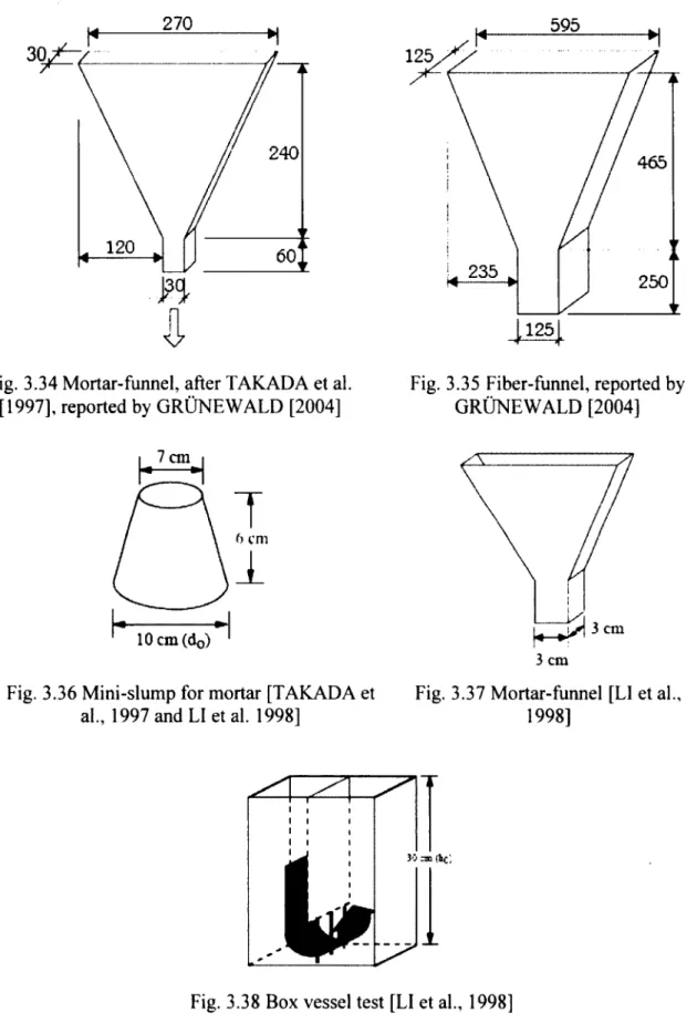
Fig. 3.34 M ortar-funnel, after TA K A D A et al. [1997], reported by G RU N EW A LD [2004]...55
Fig. 3.35 Fiber-funnel, reported by G RU N EW ALD [2004]...55
Fig. 3.36 M ini-slum p for m ortar [TAKADA et al., 1997 and LI et al. 1998]...55
Fig. 3.37 M ortar-funnel [LI et al., 1998]... 55
Fig. 3.38 Box vessel test [LI et al., 1 9 9 8 ]... 55
Fig. 3.39 Prestressed sheet piles cast with self-com pacting fiber-reinforced m ortar (left) and conventional concrete (right) [GRUN EW A LD , 2 0 0 4 ]... 57
Chapter 5 Fig. 5.1 G rain-size distribution o f 2.5-10 mm coarse aggregate (typical resu lts)... 77
Fig. 5.2 G rain-size distribution o f 5-20 mm coarse aggregate (typical resu lts)... 78
Fig. 5.3 Fiber M O -S ...80
Fig. 5.4 Fiber M U -S ...80
Fig. 5.5 Fiber M I-M A ... 80
Fig. 5.6 Fiber S T -P P ...80
Fig. 5.7 Fiber ST ...80
Fig. 5.8 Drum 80-liter capacity m ix er...87
Fig. 5.9 Drum 1 10-liter capacity m ix er...87
Fig. 5.10 open-pan 400-liter capacity m ix e r... 87
Fig. 5.11 M ixing procedure o f self-consolidating m ix tu res... 87
Fig. 5.12 Slum p flow diam eter for reference S C C ... 91
Fig. 5.13 M odified J-Ring setup with 8 b a rs ... 92
Fig. 5.14 V-funnel setup [EFNARQ, 2 0 0 2 ]... 92
Fig. 5.15 M odified L-box setup with 1 b a r ...93
Fig. 5.16 D im ensions o f caisson filling capacity setu p ... 94
Fig. 5.17 M odified co-axial Tattersall M K III viscom eter for concrete... 94
Fig. 5.18 G eom etry o f the vane determ ining the rheological flow curves [YAHIA et al., 2006] ...94
Fig. 5.19 Colum n for volum e static stability... 95
Fig. 5.20 D im ensions o f the colum n for volum e static stability test [HW ANG, 2 00 6 ]...95
Chapter 7 Fig. 7.1 D ivergence between predicted and m odified shrinkage (M O-S 0.3% m ixture)... 141
Fig. 7.2 Shrinkage prediction o f FR-SCC m ixtures using the original CEB-FIP m o d e l...143
Fig. 7.3 Shrinkage prediction o f FR-SCC m ixtures using the m odified CEB-FIP m o d e l... 144
Fig. 7.4 Shrinkage prediction o f FR-SCC m ixtures using the seven original m o d e ls ... 144
20 08]... 153 Fig. 8.2 Cracked ring concrete sp ecim en ... 153 Fig. 8.3 Sealed and unsealed concrete prism sp ecim ens...153 Fig. 8.4 D evelopm ent o f strains in the inner ring due to concrete co n tractio n...155 Fig. 8.5 Tim e for cracking o f the investigated m ix tu re s...156 Fig. 8.6 Crack w idth as function o f tim e-to-cracking for fiber-reinforced m ix tu re s... 158 Fig. 8.7 C ontour diagram s o f cracking potential o f SCC and FR-SCC m ixtures as function o f 7-d eu and 3-d Ec...160 Chapter 9
Fig. 9.1 Scope o f work for 13 m onolithic b e a m s... 163 Fig. 9.2 Scope o f work for 15 repaired b e a m ... 164 Fig. 9.3 Section view for beam e le m e n ts... 166 Fig. 9.4 Stress-strain curve from direct tension test on 20M b ars...166 Fig. 9.5 Stress-strain curve from direct tension test on 10M b ars...167 Fig. 9.6 Flexural loading system for beam elem ents...169 Fig. 9.7 M odified large L-box setup for repair-casting sim ulation... 173 Fig. 9.8 D im ensions o f modified large L-box apparatus...174 Fig. 9.9 Section A-A o f the horizontal part o f the large L -b o x ... 174 Fig. 9.10 FR-SCM (ST 1.6 %) in the large L-box...175 Fig. 9.11 P-3500 portable strain in dicator... 177 Fig. 9.12 Laterally transparent form work and holes at bottom for supports... 178 Fig. 9.13 Casting o f m onolithic beam s o f SCC and FR-SCC m ix tu res...179 Fig. 9.14 Curing under w et burlap covered by tarpaulin (or plastic sheeting) for 14 d ... 180 Fig. 9.15 A ir-drying in the labo rato ry...180 Fig. 9.16 Position o f holes, supports, and load p o in ts... 181 Fig. 9.17 Schem atic o f com posite beam sp e c im e n ...181 Fig. 9.18 C overing all reinforcem ent o f the repaired zone w ith adhesive duct ta p e ... 182 Fig. 9.19 Placing o f the PVC holes in the inverted reinforcem ent... 182 Fig. 9.20 Interm ediary h o le ... 182 Fig. 9.21 Edge ho le... 182 Fig. 9.22 Closure o f h o le s ... 183 Fig. 9.23 Fixation o f s u p p o rts...183 Fig. 9.24 Substrate casting (o f the 2A upper beam height) in inverted position...183 Fig. 9.25 Spraying the substrate w ith a set retardant liq u id ...184 Fig. 9.26 A pplication o f w ater-flash on the substrate surface... 184 Fig. 9.27 Before and after c lean in g ... 185 Fig. 9.28 Interface cleaned and duct tape rem o v ed ...185 Fig. 9.29 Lifting o f inverted and partially cast b e a m ... 185 Fig. 9.30 Rem oval o f the PVC m o ld s ...185 Fig. 9.31 M echanically roughened h o le ... 185 Fig. 9.32 O-funnel used for repair casting...186 Fig. 9.33 D im ensions o f O -funnel...186 Fig. 9.34 Casting o f the repaired zon e...187
Fig. 9.36 H andling o f repaired beam with great cau tio n ...188 Fig. 9.37 Setup scheme o f the flexural test [EL-SAYED, 2006, w ith some m odifications]... 189
Fig. 9.38 MTS 5000 data acquisition sy stem ... 189
Fig. 9.39 Recording o f data during loading... 189 Fig. 9.40 Loading and strain-control system s (dim ensions in m m )... 190 Fig. 9.41 One LV D T at m id-span and two small LV D T for m ajor c ra c k s... 191 Fig. 9.42 Small LVDT for m onitoring o f m ajor c ra c k ... 191 Fig. 9.43 Two LVDT for quality control and one small LVDT for bond con trol... 191 Fig. 9.44 Strain gauges on upper surface o f beam m id -sp a n ...192 Fig. 9.45 Strain gauges o f lateral side o f beam m id -sp a n ... 192 Fig. 9.46 M onitoring o f first crack appearance...192 Fig. 9.47 Hand m icroscope for m icro-crack m easu rem en t... 192 Fig. 9.48 M onitoring o f crack n e tw o rk ... 193 Fig. 9.49 Sam pling location on the b e a m s ... 193 Fig. 9.50 Cored b e a m ... 194 Fig. 9.51 Core for co m pression ... 194 Fig. 9.52 Test setup for shrinkage m easurem ent... 195 Fig. 9.53 In-place f c test results on cylinders cored from different types o f m onolithic beams
... 204 Fig. 9.54 In-place f ’c test results on cylinders cored from substrate concrete o f repair beam s
... 204 Fig. 9.55 In-place f ’c test results on cylinders cored from self-consolidating m ixtures used to repair b e a m s ... 205 Fig. 9.56 Rapid-chloride perm eability test results from cylinders prepared o f m ixtures used for casting o f b e a m s... 209 Fig. 9.57 D rying shrinkage and porosity test results from specim ens prepared o f m ixtures used for casting o f b e a m s ... 210 Fig. 9.58 D eflection o f self-consolidating m onolithic b eam ... 214 Fig. 9.59 D eflection o f self-consolidating vs. conventional vibrated m onolithic b eam s...214 Fig. 9.60 D eflection o f FR-SW C vs. FR-SCC m onolithic beam s... 215 Fig. 9.61 D eflection o f self-consolidating repair beam w ith synthetic fibers vs. reference m onolithic beam o f C V C ... 215 Fig. 9.62 D eflection o f self-consolidating repair beam s with hybrid and steel fibers vs.
reference m onolithic beam o f C V C ...216 Fig. 9.63 D eflection o f repair beams vs. m onolithic beam s... 216 Fig. 9.64 D eflection o f FR-SCC vs. SCC with 50% additional steel reinforcem ent in repair beam s...217 Fig. 9.65 Strains o f steel reinforcem ent and concrete o f self-consolidating m onolithic beam s
...218 Fig. 9.66 Strains o f steel reinforcem ent and concrete o f self-consolidating vs. conventional vibrated m onolithic b e a m s ...219 Fig. 9.67 Strains o f steel reinforcem ent and concrete o f FR-SW C vs. FR-SCC m onolithic beam s...220 Fig. 9.68 Strains o f steel reinforcem ent and concrete o f self-consolidating repair beam s with synthetic fibers vs. reference m onolithic beam o f C V C ... 221
Fig. 9.70 Strains o f steel reinforcem ent and concrete o f repair beam s vs. m onolithic beam s 223 Fig. 9.71 Strains o f steel reinforcem ent and concrete o f FR-SCC vs. SCC with 50% additional steel reinforcem ent in repair beam s... 224 Fig. 9.72 Crack w idth o f self-consolidating m onolithic b e a m s ...225 Fig. 9.73 Crack width o f self-consolidating vs. conventional vibrated m onolithic b e a m s 226 Fig. 9.74 Crack w idth o f FR-SW C vs. FR-SCC m onolithic beam s... 226 Fig. 9.75 Crack w idth o f self-consolidating repair beam s with synthetic fibers vs. reference m onolithic beam o f C V C ... 227 Fig. 9.76 Crack w idth o f self-consolidating repair beam s with hybrid and steel fibers vs.
reference m onolithic beam o f C V C ... 227 Fig. 9.77 Crack w idth o f repair beam s vs. m onolithic b eam s...228 Fig. 9.78 Crack w idth o f FR-SCC vs. SCC with 50% additional steel reinforcem ent in repair b eam s...228 Fig. 9.79 Crack patterns o f m onolithic beam s...233 Fig. 9.80 Crack patterns o f repaired b eam s... 236 Fig. 9.81 Beam pattern at service lo a d ... 236 Fig. 9.82 Beam pattern at failu re...237 Fig. 9.83 Relative overall perform ance o f m ixtures com pared to reference m onolithic beam m ade w ith C V C ... 240 Fig. 9.84 Relative cost-efficiency values o f m onolithic beam s com pared to reference
m onolithic beam o f C V C ... 245 Fig. 9.85 Relative cost-efficiency values o f repair beam s com pared to reference m onolithic beam o f C V C ... 246 Chapter 10
Fig. 10.1 N eutral axis positions in m onolithic and repaired b e a m s ...251 Fig. 10.2 Stress and strain variation in FR-SCC repaired beam s (ACI 544 w ith some
m odifications)...256 Fig. 0.3 Loading sy ste m ...262 Fig. 10.4 Typical correlations between experim ental and theoretical deflections o f reference m onolithic beam s o f C V C ... 266 Chapter 11
Fig. 11.1 M ixtures prepared for flexural creep te s t...272 Fig. 11.2 Beam s, cylinders, and prism s in controlled room (23 ± 2°C and 50% ± 4% R H )...273 Fig. 11.3 Form w ork used to cast beam s for flexural c re e p ...273 Fig. 11.4 Four-point concrete flexural c re e p ... 275 Fig. 11.5 Beam reinforcem ent... 275 Fig. 11.6 Four-point concrete flexural creep in m irror fashion...277 Fig. 11.7 Representation o f the applied loads on tested pair o f b e a m s...278 Fig. 11.8 Roller supports betw een the frame co m p o n en ts...278 Fig. 11.9 A djustm ent o f the principal lever... 278 Fig. 11.10 A djustm ent o f the secondary lever...278 Fig. 11.11 Tightening o f the bolt and ball on the principal le v er... 279 Fig. 11.12 Long-term deflection under sustained loading... 279
relation betw een the sustained load (kg) and load applied on the concrete beam s (kN) w hich is here replaced by a load cell during the calibration... 280 Fig. 11.15 Uniaxial com pressive load-voltage graph o f the load cell determ ined using an MTS loading m a c h in e ... 280 Fig. 11.16 Typical calibration graphs o f (a) fram e 1 (b) frame 2 ... 281 Fig. 11.17 Strain and deflection control sy stem ... 282 Fig. 11.18 Strain gauges on top surface o f beam at m id-span... 283 Fig. 11.19 C alibration o f the strain gauge indicator using unloaded reference steel b a r ... 283 Fig. 11.20 Pin glued to one side o f the beam at m id -sp a n ...284 Fig. 11.21 M easurem ent o f m id-span deflection... 284 Fig. 11.22 Free beam s w hitew ashed near the loaded beam s before the bending t e s t ...286 Fig. 11.23 Controlled-load bending test on reference beam s designated for creep te s t... 286 Fig. 11.24 Load-controlled loading sy stem ... 286 Fig. 11.25 Loading and strain-control systems for bending test on reference b e a m s...287 Fig. 11.26 Drying shrinkage kinetics o f m ixtures prepared for flexural c re e p ... 289 Fig. 11.27 D eflection at 1.4 M cr o f beam s m ade w ith SCM ST 0 .8 % ... 291 Fig. 11.28 Long-term steel reinforcem ent strain response under flexural creep te s t ...292 Fig. 11.29 Long-term concrete strain response under flexural creep t e s t ... 292 Fig. 11.30 Long-term crack w idth response under flexural creep te s t... 293 Fig. 11.31 Overall perform ance under flexural c re e p ...295 Fig. 11.32 Load-deflection response under four-point bending t e s t ...296 Fig. 11.33 Load-strain response under four-point bending t e s t ...296 Fig. 11.34 Load-crack w idth response under four-point bending te st... 296 Fig. 11.35 Crack pattern o f the reference beam s under four-point bending te s t... 298 Fig. 11.36 O verall perform ance under four-point bending te st...299 Fig. 11.37 Com parison with perform ance under flexure on larger-scale beam s in C hapter 929 9 Fig. 11.38 Com parison w ith overall perform ance under restrained sh rin k ag e ... 300 Chapter 12
Fig. 12.1 Exam ple o f saw -cut cylinder... 309 Fig. 12.2 D istribution o f coarse aggregate along cylinder h e ig h t... 309 Fig. 12.3 Effect o f consolidation level on segregation o f different concrete ty p e s... 312 Fig. 12.4 Effect o f consolidation level on segregation front o f different concrete ty p e s... 312 Fig. 12.5 Effect o f consolidation on com pressive strength o f different concrete ty p e s ... 312 Fig. 12.6 Effect o f consolidation level on splitting tensile strength o f different concrete types
... '... 313 Fig. 12.7 Effect o f consolidation energy on mean honeycom b surface ratios o f different concrete ty p e s... 313 Appendix A
Fig. A .l Predicted ACI 209 shrinkage model vs. experim ental shrinkage for F R -S C C ... 340 Fig. A.2 M odified ACI 209 shrinkage m odel vs. experim ental shrinkage for F R -S C C ... 340 Fig. A .3 Predicted A ASHTO LFRD shrinkage model vs. experim ental shrinkage for FR-SCC
Fig. A.5 Predicted CEB-FIP shrinkage model vs. experim ental shrinkage for F R -S C C ...341 Fig. A .6 M odified CEB-FIP shrinkage m odel vs. experim ental shrinkage for F R -S C C ...341 Fig. A .7 Predicted G L2000 shrinkage model vs. experim ental shrinkage for F R -S C C ...341 Fig. A .8 M odified G L2000 shrinkage model vs. experim ental shrinkage for FR -SC C... 341 Fig. A .9 Predicted B3 shrinkage model vs. experim ental shrinkage for F R -S C C ... 342 Fig. A. 10 M odified B3 shrinkage model vs. experim ental shrinkage for F R -S C C ... 342 Fig. A .l 1 Predicted ACI 209 shrinkage model vs. experim ental shrinkage for F R -S C M ...343 Fig. A. 12 M odified ACI 209 shrinkage model vs. experim ental shrinkage for F R -S C M ...343 Fig. A. 13 Predicted A ASHTO LFRD shrinkage m odel vs. experim ental shrinkage for FR-S C M ... 343 Fig. A. 14 M odified A ASH TO LFRD shrinkage m odel vs. experim ental shrinkage for FR-S C M ... 343 Fig. A. 15 Predicted CEB-FIP shrinkage model vs. experim ental shrinkage for F R -S C M ...344 Fig. A. 16 M odified CEB-FIP shrinkage model vs. experim ental shrinkage for F R -S C M ...344 Fig. A. 17 Predicted G L2000 shrinkage model vs. experim ental shrinkage for F R -S C M ...344 Fig. A. 18 M odified G L2000 shrinkage model vs. experim ental shrinkage for FR -S C M ...344 Fig. A. 19 Predicted B3 shrinkage model vs. experim ental shrinkage for F R -S C M ... 345 Fig. A .20 M odified B3 shrinkage model vs. experim ental shrinkage for F R -S C M ... 345 Fig. A .21 All Predicted shrinkage m odels vs. experim ental shrinkage for F R -S C M ...345 Fig. A.22 All modified shrinkage m odels vs. experim ental shrinkage for F R -S C M ... 345 Appendix C
Fig. C .l Relative f ’c for FR-CV C/CV C and (FR-SCC + FR -SC M )/SC C ... 347 Fig. C.2 Relative f ’c for FR -SW C /FR -SC C ...347 Fig. C.3 Relative f ' sp for FR-CV C/CV C and (FR-SCC + FR -SC M )/SC C ...348 Fig. C.4 Relative f ' sp for F R -S W C /F R -S C C ...348 Fig. C.5 Relative f r for FR-CVC/CVC and (FR-SCC + F R -S C M )/S C C ...349 Fig. C.6 Relative f r for FR -SW C /FR -SC C ... 349 Fig. C . l Relative £ c for FR-CV C/CV C and (FR-SCC + F R -S C M )/SC C ... 350 Fig. C.8 Relative E c for FR -SW C /FR -SC C ... 350
Chapter 3
Table 3.1 R ecom m endation on the norm alized bar spacing between devices [GROTH, 2000b] ...27 Table 3.2 Bridging probability density functions and efficiency factors [LI et al., 2001],
reported by CH ALM ERS [n .d .]...45 Table 3.3 Typical properties o f SCC for repair [KHAYAT, 2 0 0 6 ]... 49 Table 3.4 Fresh properties o f SCC used for reaction wall at the U nivesite de Sherbrooke
[KHAYAT, 2 0 0 6 ]... 50 Table 3.5 W orkability characteristics, test methods, and recom m ended values [HW ANG et al., 20 06]... 51 Chapter 4
Table 4.1 Shrinkage correction factors for initial m oist curing [ACI 2 0 9 ,1 9 9 2 ]...61 Table 4.2 Param eters considered in various prediction m o d e ls... 70 Chapter 5
Table 5.1 G rain-size distribution o f coarse and fine ag g reg ates... 77 Table 5.2 Physico-chem ical properties o f the used cem ent ty p e s ...78 Table 5.3 Properties o f adm ixtures u s e d ... 79 Table 5.4 G eom etric, physical, and mechanical properties o f fibers u se d ...81 Table 5.5 Typical com position o f concrete m ix tu res... 86 Table 5.6 W orkability properties and test m ethods for SCC, FR-SCC, and F R -C E M ...90 Table 5.7 Fiber volum es used for different m ixture ty p e s ... 90 Table 5.8 Blocking assessm en t... 92 Table 5.9 Samples for tests in hardened s ta te ... 97 Table 5.10 M echanical consolidation m ethods for sam pling sp ecim en s... 98 Chapter 6
Table 6.1 M ixture proportions and fresh properties o f typical m ixtures prepared for
determ ination o f mechanical p ro p erties... 102 Table 6.2 M echanical properties o f typical m ix tu res...103 Table 6.3 V olum e o f fibers used for various types o f m ix tu res... 104 Table 6.4 Total num ber o f specim ens tested for m echanical properties p redictio n...105 Table 6.5 Prediction m odels for mechanical properties w ith consideration o f fib ers... 107 Table 6.6 Prediction m odels for mechanical properties w ithout consideration o f fibers... 108 Table 6.7 Prediction m odels for f ’c and E c with respect to tim e... 111 Table 6.8 f cjexP /fcfih e o o f the investigated m ixtures using m odels considering fib e rs ...114 Table 6.9 f c{t) exp / f c{t) ,heo and f c/ t ) exp/ f c/ t ) ,heo o f the investigated m ixtures... 114 Table 6.10 T h e / , p exp / f sp ltteo and f spfexP / f s Pftheo o f the investigated m ix tu res...115 Table 6.11 f rexp / f , the,, andfrfexp / fr/theo o f the investigated m ixtures... 115 Table 6.12 E c exp / E c ,heo and E c/ exp / E cf,h eo o f the investigated m ixtures...117 Table 6.13 E c exp / E c ,heo for £ c(t) = f[£ c(28)] and £ c/ t ) exp / E c/ t ) lheo for E cj (t) = f[£ c/(28)] o f the investigated m ixtures...118
Table 6.15 Param eter com binations considered in calculation to propose prediction m odels for
f ’cfx) and E cf t ) ... 121
Table 6.16 Proposed prediction m odels for mechanical properties o f FR-SCC m ix tu res 123
Table 6.17 Proposed prediction m odels for mechanical properties o f SCC m ix tu re s 124
Table 6.18 Proposed prediction m odels for mechanical properties o f FR-SCM m ix tu re s.... 125 Table 6.19 f cf exp/ f c/theo o f the investigated m ixtures using m odels considering fibers for
selected m ix tu res...127 Table 6 . 2 0 / c(t) exp/ f c(t) theo f o r / c(t) = f ] / c(28)] o f the selected m ix tu res...127 Table 6.21 The f sp e x p /fs p theo o f selected m ix tu res... 128 Table 6.22 f rexp/ f r ,heo o f selected m ix tu res...129 Table 6.23 E c exp / E c ,heo o f selected m ix tu res... 130 Table 6.24 E j(t) exp / E c(t) ,heo for E c(i) = E c(28) o f selected m ixtu res... 131 Table 6.25 Difference in prediction accuracy between all m ixtures o f different param eters and mixtures o f com m on p aram eters... 132 Chapter 7
Table 7.1 Com position o f investigated m ixtures...138 Table 7.2 Properties o f the investigated fib e rs... 139 Table 7.3 D rying shrinkage results o f investigated m ix tu res...139 Table 7.4 O riginal shrinkage m o d e ls ... 140 Table 7.5 Predicted vs. m easured shrinkage values determ ined using various m odels before and after m odifications o f the drying shrinkage m o d e ls ...143 Chapter 8
Table 8.1 M ixture proportioning o f investigate repair m a te ria ls ... 149 Table 8.2 Test results in fresh s ta te ... 150 Table 8.3 M echanical p ro p erties... 150 Table 8.4 V isco-elastic pro p erties...151 Chapter 9
Table 9.1 M ixture proportions, fresh properties, and m odified L-box test results o f m ixtures used for sim u lation... 175 Table 9.2 Difference between the sim ulated casting and actual beam characteristics... 176 Table 9.3 Characteristics o f strain gauges used for steel reinforcem ent and concrete... 176 Table 9.4 N um ber o f specim ens sam pled w ith each beam -m ixture ty p e... 178 Table 9.5 RCP rating [ASTM C 1202]...194 Table 9.6 M ixture proportions o f concretes used for casting m onolithic beam s and repair sectio n s... 196 Table 9.7 Fresh test results o f m ixtures used for casting o f b eam s... 199 Table 9.8 M echanical properties o f various m ixtures used for casting m onolithic and repair beam elem en ts...200 Table 9.9 Sum m ary o f durability and visco-elastic properties test results o f beam concrete .208 Table 9.10 D ifferent structural perform ance param eters o f m onolithic b e a m s ... 229 Table 9.11 D ifferent structural perform ance param eters o f repaired beam s...230 Table 9.12 Com parison o f structural properties between different m ixture ty p e s... 243
m onolithic beam m ade w ith C V C ... 244 Chapter 10
Table 10.1 Prediction results o f crack load according to ACI 318 code (m onolithic vs. repair b e a m s)... 253 Table 10.2 Prediction results o f crack load according to ACI 544 code (m onolithic vs. repair b e a m s )...254 Table 10.3 Prediction results o f crack load according to CSA A23.3 (m onolithic vs. repair b e a m s )... 255
Table 10.4 Sum m ary o f crack load prediction values from different code equations 256
Table 10.5 Prediction results o f ultim ate load o f the investigated b eam s... 258 Table 10.6 Prediction o f crack w idth using ACI 318 and CSA A23.3 codes (m onolithic vs. repair b e a m s)... 261 Table 10.7 Prediction o f deflection using different codes (M -Bs vs. R -B s)... 267 Chapter 11
Table 11.1 Proportions o f the investigated m ixtures for flexural c re e p ...272 Table 11.2 Specim ens prepared per m ix tu re... 274 Table 11.3 Characteristics o f steel and concrete strain gauges used for flexural creep testing
... 283 Table 11.4 Load levels o f creep/relaxation process over tim e ... 285 Table 11.5 Fresh properties o f the investigated m ix tu re s ... 287 Table 11.6 Test method results in hardened s ta te ...290 Table 11.7 Flexural creep param eter values... 294 Table 11.8 Range o f perform ance in flexural creep o f investigated m ix tu re s... 294 Chapter 12
Table 12.1 M ixture proportions o f SW C m ixtures...305 Table 12.2 Test results in fresh state o f SW C and FR-SW C m ix tu re s ... 308 Appendix A
Table A. 1 Proposed and m odified factor correction values for all m ixtures according to each m o d e l... 339 Appendix B
Table B. 1 Effect o f param eters on eu, t cr and w cr o f different m ixture ty p es...346 Appendix D
Table D .l Prediction results o f crack load according to ACI 318 code (non-fibrous vs. fibrous b e a m s )...352 Table D.2 Prediction results o f crack load according to ACI 544 code (non-fibrous vs. fibrous b e a m s )... 353 Table D.3 Prediction results o f crack load according to CSA A23.3 code (non-fibrous vs. fibrous b e a m s)...354
Table D.5 Prediction o f crack width using ACI 318 and CSA A23.3 codes (non-fibrous beams vs. fibrous beam s)...356 Table D.6 Prediction o f deflection using different codes (plain vs. fibrous b eam s)... 357 Appendix E
Table E .l Protocol o f m echanical consolidation o f FR -SW C ... 359 Table E.2 Segregation results by im age analysis o f S W C /F R -S W C ... 360 Table E.3 Effect o f consolidation energy on mechanical properties o f SWC and F R -S W C . 361 Table E.4 Effect o f consolidation energy on honeycom b surface ratio (%) o f SWC and FR- S W C ...361
Mp To AEA CA CVC (FR-CVC) CEM (FR-CEM ) EA E c, Ef, E s f c f r f s p H RW RA (SP) L / d f M-B MIP R-B RCP RH R I SCC (FR-SCC) SCM (FR-SCM ) SWC (FR-SW C) SRA ter VEA (VM A) Vf VSI w/b = w /c - w/cm Wrr plastic viscosity dynam ic yield stress air-entraining adm ixture coarse aggregate
conventional vibrated concrete (fiber-reinforced - )
concrete equivalent m ortar, derived from CVC (fiber-reinforced - ) expansive agent
elastic m odulus o f concrete, fiber, and steel reinforcem ent, respectively com pressive strength o f concrete
m odulus o f rupture o f concrete splitting tensile strength o f concrete
high-range w ater-reducer adm ixture (superplasticizer) Fiber aspect ratio
m onolithic beam
mercury intrusion porosity Repaired beam
rapid-chloride perm eability relative hum idity
reinforcem ent index (fiber factor) = (Vf. L / d j )
self-consolidating concrete (fiber-reinforced - )
self-consolidating m ortar derived from SCC (fiber-reinforced - ) superw orkable concrete (fiber-reinforced - )
shrinkage-reducing adm ixture tim e-to-cracking
viscosity-enhancing adm ixture (viscosity-m odifying adm ixture) fiber volume
visual stability index
w ater-to-binder ratio = w ater-to-cem ent = w ater-to-cem entitious m aterials ratio, by mass
CHAPTER I INTRODUCTION
1.1 Background
M any infrastructures across the world , exist in advanced state o f degradation because o f m echanical and physical factors such as surface degradation (abrasion, erosion, cavitation, impact, and scaling), internal cracking (crystallization, perm anent or excessive structural loading), and exposure to extrem e tem peratures (such as fire and freezing). V iaducts, parking and many other structures are threatened by unexpected collapse at any tim e w ithout being able to predict tim e o f their collapse though the use o f very sophisticated destructive and nondestructive apparatus. Thus, this results in heavy human losses and material dam ages. The loss o f infrastructure also leads to painful econom ic dam age. Thus, a partial repair that can shorten the duration o f rehabilitation w ould be better than a total dem olition and reconstruction.
The partial repair procedure can be processed to extend the structure lifespan with ensuring at least the same mechanical and durability properties than those o f the existing concrete. In this repair, a total dem olition and the associated expansive econom ic consequences can be avoided. The repair efficiency depends on the quality o f the repair material and its capacity to fill the section to be repaired and to cover the reinforcem ent. The efficiency also varies w ith the repair method and the com patibility betw een the substrate and the repair m aterial to ensure a long term total bond between the two materials. In addition, the capacity o f the repair m aterial to com pletely fill the restrained spacing is function o f its capacity to flow, type o f repair material (concrete, mortar, grout, etc.), w idth o f the repair zone, and steel reinforcem ent density in this zone.
Until now adays and though their adequate mechanical strengths, the existing m aterials including concretes w ith/w ithout fibers used for repair o f concrete infrastructures are expensive in term s o f required labor and equipm ents (vibration, pum ping, etc.), placing, and execution time. On one hand, the difficulty in placem ent o f these concretes accom panied by blockage in the highly reinforced or narrow areas (including repair o f dam aged structural elem ents) results in a lacuna. On the other hand, m ost materials are applicable only for the thin repair layers; the application o f others requires special precautions for placem ent (protection from air, sunlight, high tem peratures, etc.) and curing (qualified labor, m ore material needs,
and supplem entary costs). In addition, the m ajority o f these m aterials are not designated for the structural purposes; their role is restricted in the protection o f reinforcing steel bars, filling, or esthetic purposes. Besides, the placem ent o f m aterials having adequate mechanical strengths w hich are necessary for the repair (such as CVC w ith or w ithout fibers) is often difficult given their low w orkability; for exam ple, the repair in the restricted zones w here the consolidation o f concrete cannot be done by vibration. Therefore, it is necessary to use more flow able m ixtures to ensure good filling capacity. The choice o f highly flow able repair material also requires a special attention on its stability. Indeed, the m ixture instability can increase the risk o f blockage during flow on the first hand, and decrease the bond strength between the repair material and both substrate and reinforcing bars due to the bleeding. Therefore, good stability and high filling capacity o f the repair m aterials are the m ain key requirem ents for the successful repair work, especially in the case o f beams.
The use o f high-strength concrete strength is often not sufficient if the ruin behavior occurs in brittle manner. Indeed, high strength, long lifespan, and ductile response o f concrete make a priority and efficient solution in the concrete industry. In addition, easy o f placem ent, short execution tim e, and econom ic m aterials are required in some situations such as confined areas or highly reinforced sections. For repair, the use o f w orkable and stable m aterials is also recom m ended to prevent blockage and increase the bond quality between the repair material with both substrate and steel reinforcem ent. G iven the high w orkability, adequate mechanical properties, and high durability, self-consolidating concrete (SCC) can be used in such construction and repair applications. A ctually, SCC is increasingly used for m any applications throughout the world. In some cases, SCC or self-consolidating m ortar (SCM ) containing high paste volum e do not satisfy all required criteria and can engender early-age cracking due to drying shrinkage. In this case, the use o f fibers in SCC can be a good solution on these problem s and offer better absorption o f cracking energy, higher ductility, and higher tensile strengths than non-fibrous concretes. In addition, steel fibers increase shear capacity (strength) o f the structural elem ents such as beams. The incorporation o f fibers has an influence on both w orkability and m echanical properties o f SCC, w hich depends on the physical, m echanical, and geom etrical fiber characteristics. It is im portant to select an adequate volum e o f fibers to ensure all the benefits m entioned above and yet high workability.
The com bination o f both the benefits o f using SCC (high w orkability, good stability, ease o f placing, minimal blockage during casting, high strengths, econom y, etc.) and those o f fibers (high ductility, good tensile strength, m inim um shrinkage and cracking, etc.) can m eet m ost o f all the needs for successful rehabilitation o f concrete infrastructures. In other w ords, the singular properties o f both SCC and fibers, nam ely fiber-reinforced self-consolidating concrete (FR-SCC) can have a synergetic effect on both fresh and hardened properties. Similarly, fiber-reinforced self-consolidating m ortar (FR-SCM ) can also be used for the repair o f structural and non-structural concrete elements.
For the construction o f concrete infrastructures, the FR-SCCs are not required to be used with high w orkability in most cases for many considerations. The use o f fibers tends to increase dosage o f chem ical adm ixtures. Casting o f FR-SCC with high fiber volum e can be carried out w ithout risk o f blockage if a certain level o f consolidated is applied. The mechanical
consolidation o f fibrous sem i-flowable concrete, also know n as fiber-reinforced
superw orkable concrete (FR-SW C) can be considered to be econom ical com pared to SCC in term s o f low er risk o f segregation, form work pressure characteristics, and requirem ents for chem ical adm ixtures; greater robustness, surface quality, and m echanical properties.
M any test m ethods, w hich use standard and m odified devices adapted to the nature o f these fibrous m ixtures, were carried out to optim ize the best FR-SCC m ixture proportioning. In this study, full-scale beam s were chosen as a frequently met in -s itu model o f a structural elem ent exposed to concrete degradation and loaded in flexure.
1.2 Objectives
The overall objectives o f the experim ental program undertaken in this thesis were to acquire sufficient know ledge on the main properties o f FR-SCC and FR-SCM designated for the repair o f concrete infrastructures as well as fiber-reinforced superw orkable concrete (FR- SW C) for infrastructure construction. The m ain investigated properties include workability, mechanical properties, durability, visco-elastic properties (flexural creep, drying and restrained shrinkages), structural perform ance in flexure, and a protocol o f m echanical consolidation o f FR-SW C. This study provided a great vision on the advantages o f these repair
m aterials and their possible applications and prom oted their more often use in the concrete industry.
The specific objectives are as follows:
1. To investigate on the influence o f concrete type, fiber type, and fiber volum e (as study param eters) on fresh, hardened and structural properties o f FR-SCC, FR-SW C, and FR-SCM.
2. To develop and optim ize FR-SCC, FR-SW C, and FR-SCM providing high w orkability and high stability in presence o f m edium and high fiber volumes. N ew concept o f mix design m ethod w as used to m aintain high fluidity o f these fiber-reinforced m ixtures by incorporating a certain volum e o f fibers replacing a certain volum e o f coarse aggregate in a way that the m ortar layer covering both com ponents m ust be m aintained. This relationship is based on both the coarse aggregate and fiber characteristics.
3. To perform full characterization o f the FR-SCC.
4. To develop and validate a new sim ple and econom ic technique for the repair o f concrete infrastructure adapted to the fluidity range o f FR-SCC and FR-SCM mixtures.
To predict m ost investigated properties to contribute in developm ent o f
recom m endations, guidelines, and perform ance specifications o f FR-SCC and FR- SCM.
1.3 Organization o f thesis
This thesis is divided into 14 chapters including introduction (Chapter 1), literature review (Chapters 2 to 4), and 10 other chapters for the experim ental program , test results, discussion, predictions, and conclusions, as shown in diagram o f Fig. 1.1; each chapter describes in details the m ixtures used for each m ixture, test param eters, preparation procedures, and the necessary setup used for each test m ethod to investigate a given property. In m ost chapters 6 to 12, w orkability and rheological param eters were asseced. The m ain properties o f FR-SCCs were investigated. The SCC, SCM, FR-SCM , CVC, fiber-reinforced conventional vibrated concrete (FR-CVC), and fiber-reinforced concrete-equivalent m ortar (FR-CEM ) were used as reference mixtures.
x> u 00 © O ' X! Chap. 3: Fibers and SCC Experimental program Chap. 1: Introduction oo JS <N Chap. 2: D egradation and repair o f concrete Chap. 4: M odeling o f drying shrinkage and creep
Chap. 13: Conclusions and recom m endations
Chap. 14: Conclusions et recom m andations (Francais) W orkability and rheology (com m on properties)
Chap. 5: M aterials, m ixture proportions, m ixing, and test m ethods Background and literature review
![Fig. 3.2 Effect o f fibers on fresh and hardened properties o f FR-SCC [KHAYAT et al., 2000]](https://thumb-eu.123doks.com/thumbv2/123doknet/2903416.75017/52.920.184.740.92.605/fig-effect-fibers-fresh-hardened-properties-scc-khayat.webp)
![Fig. 3.4 Effect o f R I on (a): slum p flow and (b): V -funnel [G RUN EW A LD et al., 2001]](https://thumb-eu.123doks.com/thumbv2/123doknet/2903416.75017/54.918.166.776.152.391/fig-effect-slum-flow-funnel-run-ew-ld.webp)
![Fig. 3.9 Effect o f the coarse aggregate content on the m axim um content o f steel fibers [SW AM Y, 1975]](https://thumb-eu.123doks.com/thumbv2/123doknet/2903416.75017/58.918.196.756.95.406/fig-effect-coarse-aggregate-content-content-steel-fibers.webp)
![Fig. 3.24 Influence o f the aspect ratio o f fibers on the m ortar com pressive stress-strain curve [ACI 544, 2011]](https://thumb-eu.123doks.com/thumbv2/123doknet/2903416.75017/69.919.191.771.630.905/influence-aspect-ratio-fibers-pressive-stress-strain-curve.webp)
![Fig. 3.25 Typical effect o f fiber type on the stress-strain curve o f SIFCON in com pression [ACI 544, 2011]](https://thumb-eu.123doks.com/thumbv2/123doknet/2903416.75017/70.918.222.720.220.535/typical-effect-fiber-stress-strain-curve-sifcon-pression.webp)
![Table 3.4 Fresh properties o f SCC used for reaction wall at the Univesite de Sherbrooke [KHAYAT, 2006]](https://thumb-eu.123doks.com/thumbv2/123doknet/2903416.75017/81.918.200.726.133.439/table-fresh-properties-scc-reaction-univesite-sherbrooke-khayat.webp)