Pépite | Développement de l'indentation multicyclique à l'étude des matériaux massifs, revêtus et hétérogènes
152
0
0
Texte intégral
(2) Thèse de Alberto Mejias, Lille 1, 2016. © 2016 Tous droits réservés.. lilliad.univ-lille.fr.
(3) Thèse de Alberto Mejias, Lille 1, 2016. N° d’ordre :. 42023. UNIVERSITE DE LILLE I Co-tutorial Ph.D. Thesis presented by. Alberto MEJIAS to obtain the degree of:. Ph.D. IN MECHANICAL, ENERGY AND MATERIALS OF THE UNIVERSITY OF LILLE I And Ph.D. IN ENGINEERING OF THE UNIVERSITY OF CARABOBO On the subject:. DEVELOPMENT OF MULTICYCLE INDENTATION TO STUDY SOLID, COATED AND HETEROGENEOUS MATERIALS Defended on July 7, 2016 in front of the jury: Directors: Referees: Examiners:. © 2016 Tous droits réservés.. Didier CHICOT, Professor, Université de Lille I Alberto PERTUZ, Professor, Universidad Central de Venezuela (Venezuela) Eric LE BOURHIS, Professor, Université Poitiers Gérard MAUVOISIN, Lecturer HDR, Université Rennes I Olivier BARTIER, Maître de Conférences, Université de Rennes I Francine ROUDET, Lecturer HDR, Université de Lille I Alain IOST, Professor, Arts et Métiers ParisTech Puchi CABRERA, Professor, Universidad Central de Venezuela (Venezuela) Mariana H. STAIA, Professor, Universidad Central de Venezuela (Venezuela). lilliad.univ-lille.fr.
(4) Thèse de Alberto Mejias, Lille 1, 2016. © 2016 Tous droits réservés.. lilliad.univ-lille.fr.
(5) Thèse de Alberto Mejias, Lille 1, 2016. Acknowledgment I have to thanks to God who gives me the life and the opportunity to be here, allowing me to finish successfully this Ph.D. thesis.. This work has been possible thanks to the financial support of the University of Carabobo (UC), who in spite of all difficulties made possible this academic formation. Concerning this great institute, I would like to thanks to Professor Laura SAENZ (Post-graduate director of the UC) to its support and attention on all the stages of this path.. As any undertaken project, sometimes there are inevitably moments of difficulties, but fortunately, I counted with the support and trust of my thesis director, Professor Didier CHICOT. I feel truly honored to work with you. Thanks for all the advices, for the conduction and above all for the opportunity to exploit my investigation skills. I have to express my gratitude for all the time that you invest with me to finish successfully this project. It has been honestly a gladness working with you. I hope we can keep working together in next years. Thanks again.. I also thanks to Professor Alberto PERTUZ co-director of this thesis, who encourage me to be part of this project, he was the first to support and orient me to initiate this work three years ago. Thank you very much.. I am honored and I really appreciate the gesture of M. Eric LE BOURHIS (Professeur, Université de Poitiers) and M. Gérard MAUVOISIN (Maître de Conférences HDR, Université Rennes I) by accepting to be reporters of this manuscript at l’Université de Lille 1.. Also, it has been an honor to me and I thank also to Mme. Francine ROUDET (Maître de Conférences HDR, Université de Lille 1), Mme. Mariana H. STAIA (Professeur, Universidad Central de Venezuela), M. Alain IOST (Professeur, Arts et Métiers ParisTech), M. Puchi CABRERA (Professeur, Universidad Central de Venezuela) and M. Olivier BARTIER (Maître de Conférences, Université de Rennes I) who accepted the invitation to be part of the thesis jury to examine my work.. I appreciate and express my gratitude to the Laboratoire de Mécanique de Lille (LML) for the support administrative and to l’écolde doctorale des Sciences pour l’Ingenieur for the various offered transversal programs to improve my investigation abilities.. © 2016 Tous droits réservés.. lilliad.univ-lille.fr.
(6) Thèse de Alberto Mejias, Lille 1, 2016. I can forget to express my thanks to the IUT-A’s group, specially to Xavier DECOOPMAN, Francine ROUDET, Ion Cosmin GRUESCU and Noureddine BENSEDDIQ for the great company, the coffee breaks and the advices received in this three years. Thanks to Abderrahim TALHA for his helpful assistance when I arrived here. I would also to express my gratitude to Alex MONTAGNE for his assistance at the ENSAM.. I must also show my appreciation to my colleagues Michel YETNA, Phillemon NOGNING KAMTA, and Stephania KOSSMAN for the support and the good shared moments. Good luck to all of you.. It has not been easy to be apart from my family, nevertheless, they have been there to support me in remote mode, one big thanks to my brothers, my sister and my wise and loved parents.. Specially, I want to thank to you, Scarling, my beautiful and beloved wife, for all magnificent and tremendous moments that we have shared this time.. © 2016 Tous droits réservés.. lilliad.univ-lille.fr.
(7) Thèse de Alberto Mejias, Lille 1, 2016. ~ i~. General Index Figure Index...................................................................................................................................v Table Index................................................................................................................................... xi Abstract ......................................................................................................................................xiii Nomenclature ............................................................................................................................. xv General Introduction..................................................................................................................... 1 Chapter I: LITERATURE SUMMARY ................................................................................................. 5 I.1. INTRODUCTION ................................................................................................................... 5 I.2. THE LOAD-DISPLACEMENT CURVE ........................................................................................ 6. I.2.1. Classical instrumented indentation test .......................................................................... 6 I.2.2. Multicycle protocol tests.............................................................................................. 10 I.2.3. Continuous stiffness measurement (CSM) test. ............................................................. 11 I.3. CONTACT AREA FUNCTION................................................................................................. 13 I.3.1. Oliver and Pharr’s contact area function [1] .................................................................. 13 I.3.2. Troyon et Huang’s contact area description [21] ........................................................... 14 I.3.3. Chicot et al.’s contact area function [27]....................................................................... 15 I.4. DATA CORRECTION FROM INSTRUMENTED INDENTATION TESTS ......................................... 16. I.4.1. Frame compliance of the instrument............................................................................ 16 I.4.2. Geometric correction factor ......................................................................................... 18 I.4.3. Material correction factor ............................................................................................ 19 I.5. DEFORMATION MODE AROUND THE RESIDUAL IMPRESSION ............................................... 20 I.6. INDENTATION SIZE EFFECT ................................................................................................. 22 I.6.1. Li and Bradt’s Model [44] ............................................................................................. 22 I.6.2. Nix and Gao’s Model [45]............................................................................................. 24 I.7. ANALYSIS OF HETEROGENEOUS MATERIALS ........................................................................ 26 I.8. ANALYSIS OF FILM-SUBSTRATE SYSTEMS............................................................................. 28. Ph.D. Thesis presented by Alberto MEJIAS © 2016 Tous droits réservés.. lilliad.univ-lille.fr.
(8) Thèse de Alberto Mejias, Lille 1, 2016. ~ ii ~. General Index. I.8.1. Elastic modulus from thin films .................................................................................... 28 I.8.2. Hardness from thin films.............................................................................................. 30 I.8.3. Elastic modulus from multilayer coating systems........................................................... 32 I.8.4. Hardness from multilayer coating systems .................................................................... 35 I.9. CONCLUSIONS................................................................................................................... 38 Chapter II: MATERIALS AND EXPERIMENTS ................................................................................... 41 II.1. INTRODUCTION ................................................................................................................ 41 II.2. MATERIALS....................................................................................................................... 41 II.2.1. Carbon steel samples.................................................................................................. 41 II.2.2. Hydroxyapatite coating specimens .............................................................................. 42 II.2.3. Carbon steels coated with a bilayer electroless Ni-P deposits........................................ 44 II.2.4. Metallography preparation and polishing .................................................................... 46 II.3. INDENTATION EXPERIMENTS............................................................................................. 47 II.3.1. Fundaments of the Instrumented Indentation Test (IIT) ................................................ 47 II.3.2. Description of instruments.......................................................................................... 47. II.3.3. The experimental design of the instrumented indentation test ..................................... 50 Chapter III: RESULTS AND DISCUSSION ......................................................................................... 53 III.1. EVALUATION OF HARDNESS AND ELASTIC MODULUS OF CARBON STEEL SAMPLES BY CONTINUOUS MULTICYCLE INDENTATION TESTS AND CONTINUOUS STIFFNESS MEASUREMENT 54 III.1.1. Mechanical properties evaluated by continuous multicycle indentation tests ............... 54 III.1.2. Contact area from the nanoindentation experimental contact stiffness ........................ 62 III.1.3. Conclusions............................................................................................................... 71 III.2. MECHANICAL PROPERTIES BY MULTICYCLE INDENTATION TEST FROM HETEROGENEOUS SAMPLES ................................................................................................................................ 72. III.2.1. Introduction.............................................................................................................. 72 III.2.2. Microstructure of hydroxyapatite coating samples ...................................................... 73 III.2.3. Surface condition of hydroxyapatite coatings .............................................................. 76 III.2.4. Mechanical properties from continuous multicycle Indentation tests. .......................... 76. Ph.D. Thesis presented by Alberto MEJIAS © 2016 Tous droits réservés.. lilliad.univ-lille.fr.
(9) Thèse de Alberto Mejias, Lille 1, 2016. General Index. ~ iii ~. III.2.5. Discussion................................................................................................................. 84 III.2.6. Conclusions............................................................................................................... 90 III.3. MECHANICAL PROPERTIES BY MULTICYCLE INDENTATION TEST FROM A BILAYER COATING SYSTEMS................................................................................................................................. 91. III.3.1. Introduction.............................................................................................................. 91 III.3.2. Mechanical properties from bilayer coating system ..................................................... 92 III.3.3. Discussion............................................................................................................... 102 III.3.4. Conclusions............................................................................................................. 111 General Conclusions.................................................................................................................. 113 References ............................................................................................................................... 117. Ph.D. Thesis presented by Alberto MEJIAS © 2016 Tous droits réservés.. lilliad.univ-lille.fr.
(10) Thèse de Alberto Mejias, Lille 1, 2016. ~ iv ~. General Index. Ph.D. Thesis presented by Alberto MEJIAS © 2016 Tous droits réservés.. lilliad.univ-lille.fr.
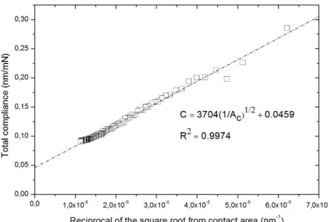
(11) Thèse de Alberto Mejias, Lille 1, 2016. ~ v~. Figure Index Figure I.2-1. Load-unload cycle from a standard instrumented indentation test. ............................... 6 Figure I.2-3. SEM micrograph from the residual impression left by a Berkovich indenter on a Hydroxyapatite coating sample. ..................................................................................................... 7 Figure I.2-4. Profile from load-displacement curve recorded froma standadrd instrumented indentation test. ........................................................................................................................... 7 Figure I.2-5. Profile of the load-displacement curve from a indentation test running a multicycle procol. .................................................................................................................................................. 11 Figure I.2-6. Representative scheme of the continuous stiffness measurements (CSM) mode. ......... 12 Figure I.3-1. Rigid cone with a vertical semi-angle 𝜓 and a spherical cap of radius 𝑅 modelling the blunt defect of the indenter tip............................................................................................................. 14 Figure I.4-1. Total compliance (𝐶𝑇) versus the reciprocal of the square root of the contact area (1/𝐴𝐶) from the data acquired by IIT over a carbon steel sample. ............................................................. 17 Figure I.4-2. Deformed surface considering it as the same that a rigid cone or sligtly curved instead.19 Figure I.5-1. Shematic representation of sink-in and pile-up phenomenon around the indenter....... 20 Figure I.8-1. Multilayer coating system sheme to analyze the contribution of each layer to the composite elastic modulus by means of the models advanced by Rahmoun et al. [68] and modified by Puchi-Cabrera et al. [69] .............................................................................................................. 33 Figure I.8-2. Composite hardness variation of a multilayer coatings from a galvanized steel as a function of the indenter displacement into surface for the for a bath immersion of 7 min. ........................... 37 Figure I.8-3. Contribution of each layer from the multilayer coating from galvanized steel specimen to the composite hardness. ............................................................................................................. 38 Figure II.2-1. SEM images of sample using a low solution concentration of CA/P. Sample surface is showed (left) and its corresponding cross-section (right)............................................................... 43 Figure II.2-2. SEM micrograph of sample using a high concentration solution of Ca/P. The surface of the sample is exhibit (left) and its corresponding cross-section (right).................................................. 43 Figure II.3-1. SEM image from the bilayer electroless Ni-P coating deposited on SAE 10210 carbon steel plate........................................................................................................................................... 45 Figure II.3-2. EDS analysis performed to identify the possible diffusion process between the coating and hardness. Fe element is absent in the electroless Ni-P coating (left), Ni element inattentive in the substrate (center) and existence of P element in both substrate and coating but more important in the electroless Ni-P coating (right). .................................................................................................... 46. Ph.D. Thesis presented by Alberto MEJIAS © 2016 Tous droits réservés.. lilliad.univ-lille.fr.
(12) Thèse de Alberto Mejias, Lille 1, 2016. ~ vi ~. Figure Index. Figure II.3-3. Scheme of the heat treatment of every single electroless Ni-P deposited on substrate plates. ........................................................................................................................................ 46 Figure II.6-1. Microhardness indenter CSM 2–107 manufactured by CSM instruments used to perform the instrumented indentation tests at the microscale range. ......................................................... 48 Figure II.6-2. Schematic of instrumented indentation test at both nanoscale and microscale. .......... 48 Figure III.1-1. Load-displacement curve registered by standard indentation tests accomplished on a SAE 1020 carbon steel specimen at maximum loads of 1, 3, 4, 6 and 10 N............................................. 55 Figure III.1-2. Load-displacement curve performed by a continuous multicycle indentation test on a steel sample. .............................................................................................................................. 56 Figure III.1-3. Ratio of ℎ𝑓 to ℎ𝑚 (∆= ℎ𝑓/ℎ𝑚) representation as function of the maximum indentation depth (ℎ𝑚) derived from every single cycle. ................................................................................. 57 Figure III.1-4. Estimation of the tip defect dimension for the utilized Berkovich indenter by means of an emission field SEM analysis. .................................................................................................... 57 Figure III.1-5. Total compliance (𝐶𝑇), or reciprocal of the experimental contact stiffness (1/S), as function of the reciprocal square root of contact area (1/𝐴𝐶). ...................................................... 58 Figure III.1-6. Elastic modulus of a SAE 1020 carbon steel sample computed from a continuous multicycle indentation test. ......................................................................................................... 59 Figure III.1-7. Martens hardness (𝐻𝑀) versus the reciprocal of the maximum indentation depth (1/ℎmax) for the SAE 1045 carbon steel sample by the proportional specimen resistance model applied to hardness computed from multicycle indentation data. .............................................................. 60 Figure III.1-8. Square of Martens hardness (𝐻𝑀2) versus the reciprocal of the maximum indentation depth (1/ℎm) for the SAE 1045 carbon steel sample by applying the strain gradient plasticity model to hardness from multicycle indentation data. .................................................................................. 61 Figure III.1-9. Comparison of the experimental contact stiffness computed from the contact area functions advanced by Oliver and Pharr [1] and Chicot et al. [27] considering 100 < ℎmax < 1900 nm .................................................................................................................................................. 65 Figure III.1-10. Fraction difference between the experimental contact stiffness and the predicted one evaluated from the Oliver and Pharr’ contact area function [1] and the one proposed by Chicot et al. [27] considering 100 < ℎmax < 1900 nm.................................................................................... 66 Figure III.1-11. Comparison of the contact stiffness by replacing the contact area function defined by Oliver and Pharr [20] and Chicot et al. [21] in Eq. (III.1-2) and considering 4 < ℎmax < 50 nm. ...... 67 Figure III.1-12. Fraction difference between the experimental contact stiffness and the contact stiffness evaluated from the contact area functions of Oliver and Pharr [20] and Chicot et al. [21] considering 4 < ℎmax < 50 nm. Contact stiffness models work better at depths greater than 10 nm............... 67. Ph.D. Thesis presented by Alberto MEJIAS © 2016 Tous droits réservés.. lilliad.univ-lille.fr.
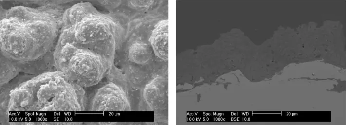
(13) Thèse de Alberto Mejias, Lille 1, 2016. Figure Index. ~ vii ~. Figure III.2-1. SEM micrographs of sample H-2 (high solution concentration) at the surface of the hydroxyapatite coating sample. ................................................................................................... 73 Figure III.2-2. SEM micrographs of sample H-2 (prepared with a high solution concentration) at the cross-section of the hydroxyapatite coating sample. ..................................................................... 74 Figure III.2-3. SEM micrographs of sample L-3 (prepared with a low solution concentration) at the surface of the hydroxyapatite coating sample. .............................................................................. 74 Figure III.2-4. SEM micrographs of sample L-3 (prepared with a low solution concentration) at the crosssection of the hydroxyapatite coating sample. .............................................................................. 75 Figure III.2-5. XRD diagram of selected coatings prepared using high concentration (H-2) and low concentration (L-3) of solution precursors indexed to standard diffraction file of HA....................... 75 Figure III.4-1. Load-displacement curve from a continuous multicycle indentation tests between 1 N and 20 N performed on a SPPS-HA coating sample........................................................................ 76 Figure III.4-2. Ratio of the residual depth to maximum indentation depth (ℎf/ℎmax) from a SPPS-HA coating sample at each cycle evaluated by a continuous multicycle indentation test. ...................... 77 Figure III.4-3. Martens hardness computed from SPPS-HA coating samples by continuous instrumented indentation tests. ........................................................................................................................ 78 Figure III.4-4. Martens Hardness and the non-linear least square analysis using the advanced model described by Eqs. (III.2-3) and (III.2-4)........................................................................................... 79 Figure III.4-5. SEM micrograph after multicycle indentation test of the hydroxyapatite coating sample H-2 (high solution concentration) showing the indenter print into surface...................................... 81 Figure III.4-6. SEM images after multicycle indentation experiment of sample L-3 (low solution concentration) showing the residual indenter print into surface. ................................................... 82 Figure III.4-7. Reciprocal of contact stiffness as a function of the reciprocal of the square root of contact area for representative samples H-2 and L-3................................................................................. 83 Figure III.4-8. Elastic modulus versus the maximum indentation depth for representative samples H-2 and L-3. ...................................................................................................................................... 84 Figure III.5-1. Models describing the elastic modulus of the hydroxyapatite coating samples (specimens prepared with high solution concentration) as function of the crystallinity volume fraction............. 89 Figure III.5-2. Models describing the hardness of the hydroxyapatite coating specimens (samples produced using high solution concentration) versus the crystallinity volume fraction...................... 89 Figure III.8-1. Load-displacement curve from a continuous multicycle indentation test performed on a bilayer electroless Ni-P coating deposited on a carbon steel plate. ................................................. 93 Figure III.8-2. Load-displacement curve from a CSM test performed on electroless Ni-P bilayer coating deposited on a carbon steel substrate. ......................................................................................... 93. Ph.D. Thesis presented by Alberto MEJIAS © 2016 Tous droits réservés.. lilliad.univ-lille.fr.
(14) Thèse de Alberto Mejias, Lille 1, 2016. ~ viii ~. Figure Index. Figure III.8-3. Load-displacement curve from multicycle indentation test performed on a electroless NiP bilayer coating deposited on a carbon steel substrate. The pile-up effect is noticeable around the indenter impression. ................................................................................................................... 94 Figure III.8-4. SEM micrograph of the residual impression from a Berkovich indenter on the sample labeled as 1020-B submitted to a continuous multicycle indentation test. ...................................... 94 Figure III.8-5. SEM images from a residual impression from a Berkovich indenter on the sample labeled as 1020-B after standard indentation test is accomplished. ........................................................... 95 Figure III.8-6. Load-displacement curve from multicycle indentation test performed on a electroless NiP bilayer coating deposited on a carbon steel substrate. The crack on corners of the indenter impression is related to the large horizontal displacement on the load-displacement curve. ........... 95 Figure III.8-7. Load-displacement curve from multicycle indentation test performed on a electroless NiP bilayer coating deposited on a carbon steel substrate. The chipping remarked on the indenter impression is related to the hysteresis loop observed in the load-displacement curve..................... 96 Figure III.8-8. SEM micrograph from the residual impression from a Berkovich indenter on the sample labeled as 1020-I after a continuous multicycle indentation test of 100 cycles is accomplished........ 97 Figure III.8-9. SEM micrograph from the residual impression from a Berkovich indenter on the sample labeled as 1020-I after standard indentation test with a maximum applied load 1 N is accomplished. .................................................................................................................................................. 97 Figure III.8-10. SEM micrograph from the residual impression from a Berkovich indenter on the sample labeled as 1020-I after standard indentation test with a maximum applied load 18 N is accomplished. .................................................................................................................................................. 98 Figure III.8-11. Calibration curve of Berkovih indenter to be employed in CSM tests on NI-P coatings. Fused silica specimen was used as the standard sample. The elastic modulus of fused silica remains constant from about 10 nm. ........................................................................................................ 99 Figure III.8-12. Elastic modulus recorded by CSM test from a bilayer Ni-P coating system performed up to a depth penetration of 2000 nm. ............................................................................................. 99 Figure III.8-13. Elastic modulus from CSM tests and continuous multicycle tests performed on a bilayer NI-P coating system................................................................................................................... 100 Figure III.8-14. Calibration curve of the Berkovih indenter used in tests. It was performed on a fused silica sample. A constant value of hardness is remarkable from approximately 100 nm. ................ 101 Figure III.8-15. Hardness continuously recorded from CSM test implemented on a bilayer Ni-P coating system performed up to a depth penetration of 2000 nm............................................................ 102 Figure III.8-16. Hardness computation from CSM tests and continuous multicycle test performed on a bilayer NI-P coating deposited on a steel plate. ........................................................................... 102. Ph.D. Thesis presented by Alberto MEJIAS © 2016 Tous droits réservés.. lilliad.univ-lille.fr.
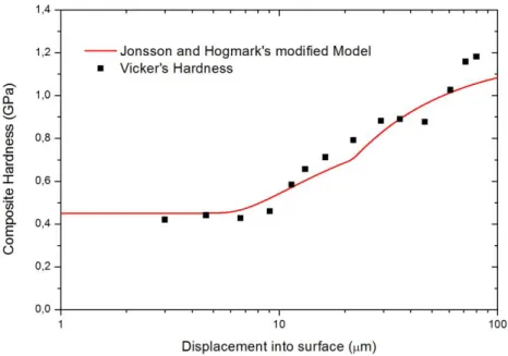
(15) Thèse de Alberto Mejias, Lille 1, 2016. Figure Index. ~ ix ~. Figure III.9-1. Hardness from multicycle indentation tests, described by the modified Jönsson and Hogmark ‘s model. .................................................................................................................... 103 Figure III.9-2. Hardness modeling from multicycle indentation tests by the modified Jönsson and Hogmark ‘s model (sample 1020-I) ............................................................................................. 103 Figure III.9-3. Modified Jönsson and Hogmark ‘s model describing the hardness behavior of sample 1020-O from multicycle indentation tests. .................................................................................. 104 Figure III.9-4. SEM micrograph illustrating the dimension of each single layer of the bilayer electroless Ni-P coating (sample named 1020-B).......................................................................................... 105 Figure III.9-5. SEM images of sample labeled 1020-B showing the dimension of each layer of the bilayer electroless Ni-P coating. ............................................................................................................ 106 Figure III.9-6. Contact Stiffness from multicycle indentation tests performed on a bilayer No-P coating system, described by the model presented in the Eqs. (III.3-6) through (III.3-11) .......................... 109 Figure III.9-7.Composite elastic modulus from multicycle indentation tests performed on a bilayer NiP coating system, predicted on the basis of the model presented in this section. .......................... 110. Ph.D. Thesis presented by Alberto MEJIAS © 2016 Tous droits réservés.. lilliad.univ-lille.fr.
(16) Thèse de Alberto Mejias, Lille 1, 2016. ~x~. Figure Index. Ph.D. Thesis presented by Alberto MEJIAS © 2016 Tous droits réservés.. lilliad.univ-lille.fr.
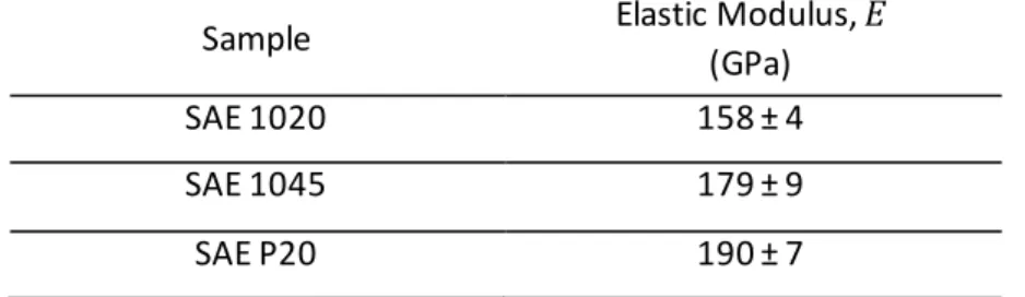
(17) Thèse de Alberto Mejias, Lille 1, 2016. ~ xi ~. Table Index Table I.8-1. Developed models to evaluate the contribution factor of film and substrate to composite modulus. .................................................................................................................................... 29 Table II.2-1. Film thickness from sprayed hydroxyapatite coatings ................................................. 43 Table III.1-1. Elastic modulus computed from continuous multicycle indentation test from SAE 1020, SAE 1045, and SAE P20 carbon steel samples. ............................................................................... 59 Table III.1-2. Hardness of carbon steel samples (mean values) described by the models of Li et Bradt [103] and Chicot [104] describing the indentation size effect from the continuous multicycle indentation test data. .................................................................................................................. 62 Table III.1-3. Contact area functions advanced by Oliver and Pharr [1] and Chicot et al. [27]............ 63 Table III.1-4. Elastic modulus and reduced elastic modulus of fused silica by replacing the models of contact area proposed by Oliver and Pharr [1] and Chicot et al. [27] into Eq. (III.1 -3) between 100 < ℎmax < 1900 nm. ...................................................................................................................... 68 Table III.1-5. Elastic modulus and reduced elastic modulus of fused silica by replacing the models of contact area proposed by Oliver and Pharr [1] and Chicot et al. [27] into Eq. (III.1-3) considering 4 < ℎmax < 50 nm. .......................................................................................................................... 69 Table III.1-6. Elastic modulus and reduced elastic modulus of SAE 1020 by replacing the contact area models proposed by Oliver and Pharr [1] and Chicot et al. [27] into Eq. (III.1-3) .............................. 69 Table III.1-7. Elastic modulus and reduced elastic modulus of SAE 1045 using the contact area approches proposed by Oliver and Pharr [1] and Chicot et al. [27] into Eq. (III.1-3) ......................... 70 Table III.1-8. Elastic modulus and reduced elastic modulus of SAE P20 replacing the contact area functions proposed by Oliver and Pharr [20] and Chicot et al. [21] into Eq. (III.1-3) ......................... 70 Table III.2-1. Surface roughness and thickness of the sprayed Hydroxyapatite coating samples........ 76 Table III.2-2. Hardness of porous and dense layer from the sprayed hydroxyapatite coatings. ......... 80 Table III.2-3. Elastic moduli from the sprayed hydroxyapatite coatings. .......................................... 82 Table III.2-4. Fitting parameters from the models describing the elastic modulus and hardness as function of the crystallinity volume fraction used (X𝐶𝑟) for all the SPPS-HAP coatings..................... 87 Table III.3-1. Elastic moduli and hardnesses of the sprayed coatings and of the substrates. ........... 105 Table III.3-2. Reduced elastic modulus and fitting parameter values by applying the model proposed in this work. ................................................................................................................................. 110. Ph.D. Thesis presented by Alberto MEJIAS © 2016 Tous droits réservés.. lilliad.univ-lille.fr.
(18) Thèse de Alberto Mejias, Lille 1, 2016. ~ xii ~. Table Index. Ph.D. Thesis presented by Alberto MEJIAS © 2016 Tous droits réservés.. lilliad.univ-lille.fr.
(19) Thèse de Alberto Mejias, Lille 1, 2016. ~ xiii ~. Abstract Title: Development of multicycle indentation to study solid, coated and heterogeneous materials.. Abstract: The assessment of mechanical properties of materials by instrumented indentation tests (IIT) have been widely performed in last years. The objective of this work is to develop a methodology to analyze the mechanical behavior of materials from the data obtained by a continuous multicycle indentation test at the microscale of loads so as to limit the problems associated with the heterogeneity of the materials and to increase the amount of data for the study of thick coatings that only nanoscale analysis does not provide in the case of heterogeneous coatings. To validate our approach, it was study the hardness and the elastic modulus of homogeneous bulk materials (carbon steels), heterogeneous dense coating (hydroxyapatite), and a two-layers coating material (NickelPhosphorus). The study of homogeneous bulk materials allowed us, first, to validate the methodology. It is also proposed a model to estimate the hardness and elastic modulus of hydroxyapatite coatings considering the compaction of the material during the indentation process. Second, it is proposed to associate the hardness and elastic modulus to the volume fraction of crystallinity. Finally, from the multicycle indentation tests performed on the electroless Ni-P bilayer coating, a new approach is advanced to assess the elastic modulus of each layer from the expression of the reciprocal of the experimental contact stiffness as function of the contact area originally proposed by Tricoteaux for a monolayer system, but now linked to a multilayer model based on the weight function suggested by Korsunsky.. Keywords: multicycle indentation test, mechanical properties, heterogeneous and coated materials.. Ph.D. Thesis presented by Alberto MEJIAS © 2016 Tous droits réservés.. lilliad.univ-lille.fr.
(20) Thèse de Alberto Mejias, Lille 1, 2016. ~ xiv ~. Abstract. Résumé Titre : Développement de l'indentation multicyclique à l'étude des matériaux massifs, revêtus et hétérogènes.. Résumé : L'évaluation des propriétés mécaniques des matériaux par essais d’indentation instrumentée (IIT) a été largement étudiée ces dernières années. L'objectif de ce travail est de développer une méthodologie pour analyser le comportement mécanique des matériaux à partir des données obtenues par indentation multicyclique à une échelle microscopique de manière à limiter les problèmes liés à l’hétérogénéité des matériaux et à augmenter le nombre de données pour l’étude des revêtements épais que seule l’analyse nanométrique ne permet pas de fournir dans le cas de revêtements hétérogènes. Pour valider notre approche, nous étudions la dureté et le module d'élasticité de matériaux massifs homogènes (aciers au carbone), de revêtement épais hétérogène (hydroxyapatite), et de revêtement bicouche (Nickel-Phosphore). L’étude des matériaux massifs homogènes nous a permis, tout d’abord, de valider la méthodologie. Nous proposons également un modèle pour estimer la dureté et le module d’élasticité des revêtements d’hydroxyapatite en considérant la compaction du matériau pendant l’indentation. D’autre part, nous proposons de relier la dureté et le module d'élasticité à la fraction volumique de cristallinité. Enfin, à partir de l’indentation multicyclique effectuée sur le revêtement Ni-P bicouche, nous proposons un modèle pour évaluer le module d'élasticité de chaque couche à partir de l’expression de l'inverse de la raideur expérimentale de contact en fonction de l’aire de contact proposée initialement pour un monocouche par Tricoteaux que nous couplons également à une approche multicouche basée sur le modèle de Korsunsky.. Mots Clés : essais multicycliques, propriétés mécaniques, matériaux hétérogènes et revêtus. Ph.D. Thesis presented by Alberto MEJIAS © 2016 Tous droits réservés.. lilliad.univ-lille.fr.
(21) Thèse de Alberto Mejias, Lille 1, 2016. ~ xv ~. Nomenclature 𝑎, contact radius between the indenter and surface during indentation 𝑎1 , parameter of the proportional specimen resistance model 𝑎 2, parameter of the proportional specimen resistance model 𝛼, geometric correction factor of the contact area suggested by Bec et al. 𝛼1 , fitting parameter from the Antunes et al.’s model 𝛼2 , fitting parameter from the Doerner and Nix ‘s model 𝛼3 , fitting parameter from the Menčík et al.’s model 𝛼4 , fitting parameter from the second Menčík et al.’s model 𝐴, theoretical contact area 𝐴 C, projected contact area 𝐴 m, true contact area 𝑎 F, film volume fraction contributing with composite hardness or elastic modulus. 𝑎P, volume fraction of the porous zone contributing with the composite hardness 𝛽, geometric correction factor 𝐵, geometric coefficient from the contact area function advanced by Troyon and Huang 𝐶, compliance of the sample 𝐶f, frame compliance of the instrument 𝐶i, fitting parameters from the contact area function advanced by Oliver and Pharr ( 𝑖 = 1, ⋯ , 8) 𝐶T, total compliance of the system Δ, ratio of the final depth and the maximum indentation depth 𝛥L−B, Li and Bradt’s parameter to quantify the indentation size effect 𝛿, indentation depth (ℎ) to film thickness ratio (𝑡) 𝑑, indenter diagonal from a Vickers’s impression 𝐸, elastic modulus of sample 𝐸𝑎, elastic modulus from the amorphous phase of the material 𝐸𝐶𝑟, elastic modulus from the crystalline phase of the material 𝐸𝐶, composite elastic modulus from a substrate-film system 𝐸𝐹, elastic modulus of a film 𝐸i, elastic modulus of a diamond indenter 𝐸R, reduced modulus of the sample 𝐸RF, reduced modulus of the film on a coated material 𝐸RC, reduced composite modulus from film-substrate material Ph.D. Thesis presented by Alberto MEJIAS © 2016 Tous droits réservés.. lilliad.univ-lille.fr.
(22) Thèse de Alberto Mejias, Lille 1, 2016. ~ xvi ~. Nomenclature. 𝐸RS, reduced modulus of the substrate from a coated material 𝐸𝑆, elastic modulus of a substrate 𝜀, geometric factor depending on the indenter shape 𝑓1 , weight function from Antunes et al. ’s model 𝑓2 , weight function from Doerner and Nix’s model 𝑓3 , weight function from Menčík et al. ’s model 𝑓4 , weight function from the second model by Menčík et al. 𝑓𝑛 , weight function from the model by Korsunsky et al. Φ, weight function from Gao et al.’s model 𝛾, correction factor depending on material proposed by Hay et al. 𝜑, parameter of the model advanced by Janzen 𝜑1, factor contribution from phase 1 to the mechanical property of the material 𝜑2, factor contribution from phase 2 to the mechanical property of the material 𝐻, hardness of sample 𝐻0 , macrohardness 𝐻𝑎, amorphous phase hardness 𝐻𝐶, composite hardness from a substrate-film system 𝐻𝐶𝑟, crystalline phase hardness 𝐻D, hardness of densified layer coating 𝐻𝐹, hardness of a film from a coated material 𝐻𝐿𝑆𝐹, hardness length-scale factor 𝐻𝐼𝑇, hardness from instrumented indentation test 𝐻𝑀, Martens hardness 𝐻𝑀0, Martens macrohardness 𝐻P, hardness of porous layer coating 𝐻𝑆, hardness of a substrate from a coated material ℎ, actual indentation depth ℎ 0, indentation depth corrected by the blunt defect of the indenter tip ℎ ∗, characteristic scale-length which characterizes the indentation size effect ℎ b, tip defect dimension ℎ 𝐶, contact indentation depth ℎ f, final indentation depth ℎ i, translation in depth to replace the zero shift of the load from Chicot et al.’s model ℎ max, maximum indentation depth ℎ meas, indentation depth registered by the instrument Ph.D. Thesis presented by Alberto MEJIAS © 2016 Tous droits réservés.. lilliad.univ-lille.fr.
(23) Thèse de Alberto Mejias, Lille 1, 2016. ~ xvii ~. Nomenclature. ℎ T, theoretical plastic penetration depth from Bec et al.’s model 𝜆, parameter from the models advanced by Hill, Budianski and Mossotti-Clausius 𝐾, factor depending on material in the power law advanced by Oliver and Pharr 𝑘 𝐻, adjustable parameter from the Humbert et al.’s model 𝑘 𝑘, fitting parameter from the Korkunsky et al.’s model 𝑘 JH, fitting parameter Jönsson and Hogmark’s model 𝑘 𝑃, fitting parameter from Puchi-Cabrera’s model 𝜅, fitting parameter from the model presented in this work 𝑚, exponent depending on material in the power law advanced by Oliver and Pharr 𝑚𝑝, exponent from advanced by Puchi-Cabrera’s model. 𝜓, semi-angle of the conical indenter equivalent to a pyramidal one 𝑃, load on sample 𝑃0, deviation load from Chicot et al. ’s model 𝑃max, maximum load applied on sample 𝑆, experimental contact stiffness 𝑆𝐶, composite contact stiffness 𝑆𝑆, contact stiffness from the substrate 𝑆F, contact stiffness from the film 𝑡F, thickness of the film 𝜐, Poisson’s coefficient of the material specimen 𝜐i, Poisson’s coefficient of the diamond indenter 𝜉, the semi-angle between the two opposite faces of a pyramidal indenter 𝜒, mixing parameter from Halpin–Tsai's model 𝑋𝐶𝑟, crystallinity volume fraction 𝑌1, mechanical property of phase 1 of a composite material 𝑌2, mechanical property of phase 2 of a composite material 𝑌𝐶, mechanical property of a composite material. Ph.D. Thesis presented by Alberto MEJIAS © 2016 Tous droits réservés.. lilliad.univ-lille.fr.
(24) Thèse de Alberto Mejias, Lille 1, 2016. Ph.D. Thesis presented by Alberto MEJIAS © 2016 Tous droits réservés.. lilliad.univ-lille.fr.
(25) Thèse de Alberto Mejias, Lille 1, 2016. ~ 1~. General Introduction Instrumented indentation tests have been extensively implemented in the assessment of several mechanical properties of materials. Many difficulties have been overcome in the assessment of mechanical properties by using this technique. As result of the increasing interest in this field, the development of models to describe the variations of mechanical properties by instrumented indentation have been proposed in last decades. From microscale to nanoscale, and more recently ultra-nanoscale, these tests have been implemented to compute the mechanical response of bulk and coating materials to evaluate its application in different industrial fields. With the aim of contribute to this important field of the science the objective of this work is to develop a methodology to analyze and to interpret the data provided from a continuous multicycle indentation tests at the microscale of loads to overcome the difficulties inherent to the heterogeneities of materials or the thickness measurement of coated systems where the indentation tests at a nanoscale range of loads could not provide enough information to describe the variations of mechanical properties, i.e. hardness and elastic modulus, as function of an increasing loading or deeper displacement of the indenter. With this objective, this work has been divided in three chapters, the first one concerns the literature summary supporting the present developed research, the second indicates the materials and experiments executed into this investigation, and finally, the third chapter where the results of the applied methodology are shown and discussed according with the considered materials under analysis.. The chapter I is presented to the reader to establish the state of the art into the indentation field, this first chapter is dedicated to explain the basis of the data analysis acquired and recorded by the indentation instruments at microscale and nanoscale ranges. A review of relations between the applied load on sample and the displacements of the indenter into the surface obtained by the instrument is presented. Moreover, concerning the data treatment, the notion of the frame compliance is developed to take into account the deflection occurring into the specimen-instrument system. The load-displacement curve acquired by the instrumented indentation tests is presented and described. Additionally, the possible mechanical responses of the material surface beneath the indenter are expounded to be taken into account on the estimation of the contact area. Considering this contact area between the indenter and the specimen surface, one of the most important parameters to evaluate, some models to estimate it are explained and physically interpreted. Then, previous investigations to compute hardness and elastic modulus are detailed. The data treatment regarding the phenomena occurring throughout the indentation test are showed and explained. The continuous multicycle protocol and continuous stiffness measurement mode are presented to use Ph.D. Thesis presented by Alberto MEJIAS © 2016 Tous droits réservés.. lilliad.univ-lille.fr.
(26) Thèse de Alberto Mejias, Lille 1, 2016. ~2 ~. General Introduction. them in the determination of mechanical properties from more complex systems and test settings such as film-substrate or heterogeneous systems.. The second chapter presents to the reader the material specimens and the characteristic of indentation experimentations developed in this research. Concerning the materials, three general sort are analyzed such as homogeneous, heterogeneous, and coated materials. The description of surface preparation or condition of samples surfaces is detailed to be after considered into the data analy sis from the load-displacement curves. The general functionality of the instrument is explained and the differences between the two scales of measurement is point out. The presented experimental design is based on the available material specimens so as to evaluate their mechanical properties by submitting them to a continuous multicycle test at microscale range to estimate the influence of loadunload sequences into the mechanical response of the material.. Finally, in chapter III, the results and discussion are presented to the reader. With the aim to contribute to the progress of this important field a different methodology by using a continuous multicycle indentation test is developed and analyzed to be implemented in different sorts of materials, from homogenous to heterogeneous materials, and from bulk to coated materials. The results of the present work are divided in three parts: the first part stands for a homogenous material, in this case represented by the carbon steel samples; the second, by considering the analysis over heterogeneous materials exemplified by the hydroxyapatite coatings; and, the third one, which involves the analysis performed on film-substrate systems typified by Ni-P electroless coatings specimens. Along this chapter, the results are displayed and discussed to ponder the influence of the load-unloading sequences into the assessment of their mechanical properties, i.e. hardness and elastic modulus, when this samples are submitted to continuous multicycle tests. The analysis of the results commences for the carbon steel samples (first part) to be extend after to examine a heterogeneous material represented by the hydroxyapatite coatings samples (second part), and afterwards, to be implemented to bilayer Ni-P coatings specimens (third part). The acquired data is submitted to corrections due to the compliance frame of the instrument, blunt defect of the indenter tip, and the deformation of the material beneath the indenter governed by the Poisson’s coefficient of the material. According with the existing background, the response of the material around the indenter is computed to describe the contact area between the indenter and the surface of the sample. The obtained data from carbon steel samples is computed to evaluate the comportment of the elastic modulus as function of the maximum indentation depth reaches at each cycle of the loading-unloading sequences. Afterwards, the second part pretends to ponder the methodology applied to heterogeneous materials, mechanical properties of solution precursor plasma sprayed hydroxyapatite (SPPS-HA) coatings are studied using the Ph.D. Thesis presented by Alberto MEJIAS © 2016 Tous droits réservés.. lilliad.univ-lille.fr.
(27) Thèse de Alberto Mejias, Lille 1, 2016. ~ 3~. General Introduction. continuous multicycle indentation test. The mechanical properties are determined by means of indentation experiments in the microscale range of loads to limit the influence of the heterogeneities of the microstructure as well as the roughness over the surface of the coating for which the effects are predominant at the nanoscale range of loads. The third part is developed with the aim of extend the analysis of multicycle indentation tests beyond bulk materials, and they are also implemented to a coated system. A bilayer Ni-P coating system is evaluated when it is submitted to CSM at a nanoindentation range and continuous multicycle indentation at a microindentation range. Physical models to study multilayer systems are applied to calculate the hardness and elastic modulus behavior of each layer from the electroless Ni-P coatings deposited on carbon steel plates.. It should be point out that this work has been developed as results of the continuous research in the instrumented indentation field which is sustained by previous publications in reviews and congress.. Publications at international reviews of Rank A: 1. Mejias A, Candidato RT, Chicot D, Pawlowski L. Mechanical properties by instrumented indentation of solution precursor plasma sprayed hydroxyapatite coatings: Analysis of microstructural effect, Surface and Coatings Technology, Volume 298, 25 July 2016, Pages 93102 2. Benarioua Y, Mejias A, Roudet F, Iost A, Chicot D, Hardness-load modelling applied to multilayer galvanized coatings. Surface Engineering, Volume 32, Issue 3, Pages 194 -200, 2016. 3. Nogning Kamta P, Mejias A, Roudet F, Louis G, Touzin M, Chicot D, Creep indentation analysis of T22 and T91 chromium based steels. Materials Science and engineering A, Volume 652, Pages 315-324, 15 January 2016. 4. Yetna Njock M, Chicot D, Ndjaka JM, Lesage J, Decoopman X, Roudet F, Mejias A. A criterion to identify sinking-in and piling-up in indentation of materials. International Journal of Mechanical Sciences, Volume 90, Pages 145-150, January 2015.. Publication at National review: 1. Yetna N’Jock M, Chicot D, Ndjaka JM, Lesage J, Decoopman X, Roudet F, Mejias A, A simple criterion to identify the deformation mode in indentation. Matériaux & Techniques, Volume 103, 603 - 8 pages, 2015. Congress communications: 1. Sokołowski P, Mejias A, Chicot D, Musalek R, Nylen P, Pawłowski L. The evaluation of mechanical properties of suspension plasma sprayed zirconia coatings having various Ph.D. Thesis presented by Alberto MEJIAS © 2016 Tous droits réservés.. lilliad.univ-lille.fr.
(28) Thèse de Alberto Mejias, Lille 1, 2016. ~4 ~. General Introduction. microstructures. International Thermal Spraying Conference and Exposition, ITSC 2016, Shanghai, China, (10-12 May 2016). 2. Mejias A, Chicot D, Decoopman X, Montagne A, Roudet F, Iost A. Multi-scale approach of the instrumented indentation technique on the fracture toughness estimation. Indentation 2014, 10-12 décembre 2014, INSTITUT CHARLES SADRON, Strasbourg -France.. Ph.D. Thesis presented by Alberto MEJIAS © 2016 Tous droits réservés.. lilliad.univ-lille.fr.
(29) Thèse de Alberto Mejias, Lille 1, 2016. ~ 5~. Chapter I: LITERATURE SUMMARY I.1. INTRODUCTION By means of instrumented indentation tests (IIT) the mechanical properties of materials, such as elastic modulus [1, 2] , hardness [1, 3], fracture toughness [4, 5], among others can be assessed [6, 7, 8, 9]. The development of models to describe the mechanical behavior and variations of mechanical properties of materials have been studied in last decades [1, 2, 10, 11]. In order to establish the state of the art in this field, this first chapter is devoted to explain the basis of the analysis of the data acquired and recorded by microindentation and nanoindentation instruments. As it will be explained, the examination of the relation between loads and displacements obtained by the instrumented indentation tests is not so obvious, and the selection of the path to evaluate this data will depend of numerous variables and concerns, starting from the compliance of the specimen-instrument system passing through the examination of the mechanical response of the material surface beneath the indenter, until mechanical phenomena such as diffusion, porosity or microcracks present in the material. First all, the description of the load-displacement curve is carried out with the purpose of settle into the source of the data to be analyzed. The contact area between the indenter and the specimen surface, one of the most important parameters to evaluate, is defined and some of the models to estimate it are explained and physically interpreted. Immediately, the approaches advanced in earlier investigations to obtain the hardness and elastic modulus are explained. Afterwards, the improvements to take into account for the data treatment are explained in detail with the view to understand and consider all phenomena taking place in the surface of the sample during the course of the indentation test. To extent the evaluation of mechanical properties to complex systems and test settings, the continuous multicycle protocol and continuous stiffness measurement mode are described to use them in the determination of properties from film-substrate or heterogeneous systems by considering the phenomena occurring in the indentation test under this kind of condition. Among these phenomena, the concept of the indentation size effect is developed to realize that hardness value depends on multiples factors, and above all on the magnitude of loads applied on its computation. Additionally, models to calculate the contribution of every single layer or substrate from a multilayer coating system to the composite hardness or composite elastic modulus are carefully explained to be applied to multilayer coating systems.. Ph.D. Thesis presented by Alberto MEJIAS © 2016 Tous droits réservés.. lilliad.univ-lille.fr.
(30) Thèse de Alberto Mejias, Lille 1, 2016. ~6 ~. Chapter I: Literature Summary. I.2. THE LOAD-DISPLACEMENT CURVE I.2.1. Classical instrumented indentation test From instrumented indentation tests (IIT) mechanical properties of material, such as hardness and elastic modulus, can be assessed from small specimens using the experimental data acquired of loads and depths of penetration from tests [1, 2, 3]. From an overall point of view, a representative test consists in initiate an increasing loading on a material surface from zero to a maximum predefined. Load on Sample, P. force and then from the latest back to zero, as it is illustrated in Figure I.2-1.. Pmax. time, t Figure I.2-1. Load-unload cycle from a standard instrumented indentation test.. Depending on the testing material a plastic deformation can take place and, at the time, a residual impression from the indenter is left into the surface of the specimen, for example, as it can be observed in Figure I.2-2. Using optical techniques, it is possible to estimate the size of the residual impression of the indenter, or, also called the projected contact area, marked by the indenter into the surface. However, well-knowing the geometry of the indenter and the maximum depth of penetration, it is possible to estimate the contact area between the indenter and the surface at the maximum load, from which the hardness of the material can be computed. Following with the experimentation enlightenment, afterwards the maximum load is applied on surface, immediately, the load on the indenter is withdrawn and the surface of the material tries to recover to its initial position but it is not usually allowed owing to the plastic deformation occurring in the course of the indentation test [12]. Considering the estimation of the elastic modulus of the material under study, normally, the initial portion of the unloading part of the curve is analyzed where a small portion of this elastic recovery is registered as a result of the relaxation of the elastic strain occurring within the material [12]. Figure. Ph.D. Thesis presented by Alberto MEJIAS © 2016 Tous droits réservés.. lilliad.univ-lille.fr.
(31) Thèse de Alberto Mejias, Lille 1, 2016. ~ 7~. Chapter I: Literature Summary. I.2-3 illustrates the profile of load-displacement curve obtained by a standard instrumented indentation test.. Pmax. loa. ng. Un. Lo. i ad. din. g. Load on sample, P. Figure I.2-2. SEM micrograph from the residual impression left by a Berkovich indenter on a hydroxyapatite coating sample.. S. hf hC. hmax. Displacement into surface, h Figure I.2-3. Profile from load-displacement curve recorded from a standard instrumented indentation test.. In next sections, the methodology to analyze the data acquired by the instrumented indentation test to compute the elastic modulus and hardness will be explained taking into account and applying the corrections terms and factors to the experimental values obtained from these tests. It is important to Ph.D. Thesis presented by Alberto MEJIAS © 2016 Tous droits réservés.. lilliad.univ-lille.fr.
(32) Thèse de Alberto Mejias, Lille 1, 2016. ~8 ~. Chapter I: Literature Summary. realize that the methodology to be described ahead relies on the hypothesis that an elastic-plastic loading is followed by an elastic unloading with no plastic deformation taking place on the unloading part of the indentation process [12]. Normally, the reduced elastic modulus (𝐸𝑅) estimated by indentation test is related directly proportional to the slope of the unloading curve at the maximum 𝑑𝑃. load, i.e. the slope at maximum indentation depth ( )| 𝑑ℎ. ℎ=ℎmax. , and inversely proportional to the. projected contact area (𝐴 C), as it is expressed in the following relation:. 𝐸𝑅 =. 1 √𝜋 𝑑𝑃 ( )| 2 √𝐴 C 𝑑ℎ ℎ=ℎmax. (I.2-1). Meanwhile, the hardness 𝐻𝐼𝑇 (which stands for instrument hardness) can be assessed from the maximum indentation load (𝑃max ) divided by the projected contact area (𝐴 C), mathematically denoted by:. 𝐻𝐼𝑇 =. 𝑃max 𝐴C. (I.2-2). Oliver and Pharr [1] proposed from Eq. (I.2-1) the evaluation of the reduced elastic modulus of a material calculated from the unloading part of the load-displacement curve rewriting it into the resulting equation:. 𝐸R =. √𝜋 1 1 2 √𝐴 C 𝐶. (I.2-3). Where the parameter 𝐶 denotes the compliance of the sample to be examined. The reduced elastic modulus (𝐸R) comprises the elastic properties from the specimen and the indenter as function of their elastic moduli and Poisson’s coefficients defined by: 1 1 − 𝜐2 1 − 𝜐i2 = + 𝐸R 𝐸 𝐸i. (I.2-4). Where the elastic modulus for a diamond indenter (𝐸i) and the Poisson’s coefficient (𝑣i) are equal to 1140 GPa and 0.07, respectively [13]. The contact area (𝐴 C) is then calculated as a function of the experimental indentation contact depth (ℎ C), and the geometric shape of the indenter, e.g. when a perfect Berkovich indenter is used, it can be expressed in the subsequent equation: Ph.D. Thesis presented by Alberto MEJIAS © 2016 Tous droits réservés.. lilliad.univ-lille.fr.
(33) Thèse de Alberto Mejias, Lille 1, 2016. Chapter I: Literature Summary. 𝐴 𝐶 = 24.5ℎ 2C. ~ 9~. (I.2-5). Where the experimental indentation contact depth (ℎ C) is evaluated as function of the maximum force applied (𝑃max) on the surface, the maximal indentation depth (ℎ max) and the experimental contact stiffness (𝑆) as it showing next [1]:. ℎ 𝑐 = ℎ max − 𝜀. 𝑃max 𝑆. (I.2-6). The coefficient 𝜀 is a geometric factor depending on the geometric nature of the indenter. In the event that a flat punch indenter is used then 𝜀 = 1, for a conical indenter is utilized 𝜀 = 0.72 and if a spherical or paraboloid indenter is adopted for the study then 𝜀 = 0.75 instead [1]. The compliance factor (𝐶) in Eq. (I.2-3) derives from the reciprocal of the experimental contact stiffness (1/𝑆) determined from the slope of the upper portion of the unloading data at the maximum load from the load-displacement curve at the maximum indentation depth (illustrated in Figure I.2-3) as it is expressed in the next relation:. 𝐶=. 1 𝑑ℎ = ( )| 𝑆 𝑑𝑃 ℎ=ℎmax. (I.2-7). From the work realized by Oliver and Pharr [1], the unloading part of the curve can be modelled by means of a power law represented by: 𝑃 = 𝐾(ℎ − ℎ f )𝑚. (I.2-8). where 𝐾 and 𝑚 are material depending constants estimated by a regression of a least square analysis, and ℎ f is the residual or final indentation depth left by the indenter into the surface after the total withdrawal of the indenter.. For the fitting procedure corresponding to the unloading data from the load-displacement curve to the Eq. (I.2-8), only the data ranging between 40% and 98% of the maximum load is recommended to use in order to avoid possible incidence of the data at the unstable beginning of the unloading part at the maximum load and just before the unloading process be completed [1, 14]; according to this consideration, from Eqs. (I.2-7) and (I.2-8), it is possible to write the compliance factor as coming:. Ph.D. Thesis presented by Alberto MEJIAS © 2016 Tous droits réservés.. lilliad.univ-lille.fr.
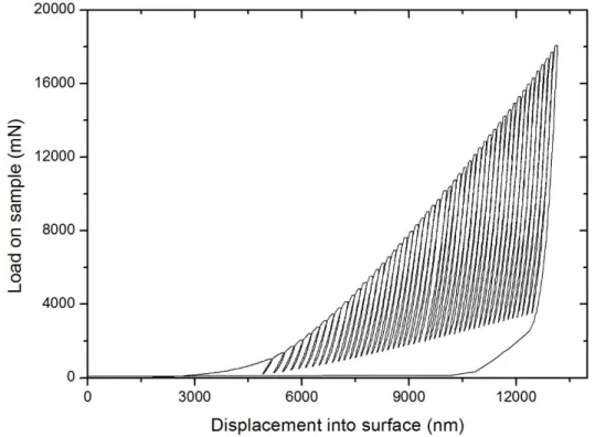
(34) Thèse de Alberto Mejias, Lille 1, 2016. ~ 10 ~. 𝐶=. Chapter I: Literature Summary. 1 1 = 𝑆 𝑚𝐾(ℎmax − ℎ𝑓)𝑚−1. (I.2-9). By regarding the Eq. (I.2-3), the estimation of the reduced elastic modulus (𝐸R) relies on the accuracy of the definition and assessment of the projected contact area (𝐴 C). The evaluation of this one will depend above all on the mechanical response of the surface around the indenter.. Some deviations from the classic load-unload test can be performed by instrumented indentation tests. In this way, partial unloadings, multicycle loading-unloading sequences, superimpose a harmonic frequency to the nominal value of the force, and change the dwell time at the maximum load can be set to study the behavior of the mechanical properties of the material. Moreover, the form of the loaddisplacement curve can indicate additional information about the phenomena related to the mechanical response of the material under indentation that permits the identification of non -linear occurrences such as cracking, chipping, delamination of films or phase transformations [12].. I.2.2. Multicycle protocol tests. Concerning the instrumented indentation tests, there are many possibilities to study the mechanical behavior under different conditions. One of them, it is the possibility to establish a continuous multicycle protocol. In this case, the test involves sequences of loading and unloading into the surface of the sample. Normally, the increasing loading can be done continuously or by little increments as illustrated in Figure I.2-4. If the study implicates the measurement of changes in elastic modulus and hardness with the indentation depth, then partials unloading could be set contributing to the acquisition of the measurement of the contact stiffness (. 𝑑𝑃 𝑑ℎ. = 𝑆) at one and all the cycles of the. continuous multicycle test.. When the continuous multicycle protocol has to be defined, the instrument could be framed into load or depth control depending on the aim of the analysis. In the same way, the software controlling the instrument generally allows to customize the dwell time at each load increasing cycle at the maximum load preset. This period of holding at each cycle permits to become stable the couple instrumentsample before the unloading takes place. In other cases, the dwell time could be set with the purpose to measure creep within the material or the thermal drift of the instrument. The number of cycles, the load increase (ΔP), and the dwell time at the maximum and minimum load of every cycle could be defined by means of the indentation software. Additionally, in some instruments the acquirement of Ph.D. Thesis presented by Alberto MEJIAS © 2016 Tous droits réservés.. lilliad.univ-lille.fr.
(35) Thèse de Alberto Mejias, Lille 1, 2016. Chapter I: Literature Summary. ~ 11 ~. the stiffness of the contact, between the indenter and the surface, can be done superimposing a harmonic load signal that is added to the nominally increasing load [1, 12], and it is named as a continuous measurements of the contact stiffness.. Figure I.2-4. Profile of the load-displacement curve from an indentation test running a multicycle procol.. I.2.3. Continuous stiffness measurement (CSM) test. The continuous stiffness measurement (CSM) mode lets to measure the contact stiffness during the loading path of a standard indentation test. To achieve this objective, a harmonic load signal is superimposed and added to the nominally increasing load, as can be observed in Figure I.2-5. The displacement response of the indenter on the material at the excitation frequency and the phase angle between the two are measured continuously as a function of depth. Solving for the in-phase and outof-phase portions of the response results in an explicit determination of the contact stiffness (𝑆) as a continuous function of the depth [1, 15, 16].. Oliver and Pharr [1] showed that a continuous and immediate change in the contact stiffness throughout unloading its correlated to a change in the contact area, this affirmation was based on the fact that carrying out an indentation experiment using a Berkovich indenter over a sample of an electropolished tungsten at very low loads, e.g. 0.5 mN and less, it was shown that a purely elastic deformation occurred, it means, that the impression into the surface fully recovers afterward the complete unloading of the indenter, and furthermore, there was a superposition on the plot of th e loading and unloading parts of the curves. Consequently, both contact area and contact stiffness were directly correlated and their increase or/and decrease were proportionally according to relationships Ph.D. Thesis presented by Alberto MEJIAS © 2016 Tous droits réservés.. lilliad.univ-lille.fr.
(36) Thèse de Alberto Mejias, Lille 1, 2016. ~ 12 ~. Chapter I: Literature Summary. that depend on the geometric shape of the indenter. As a primary conclusion of this fact, it was settle that changes in values of the stiffness of the contact are associated with variations in values of contact. loa. ng. Pmax. Un. Lo. i ad. din. g. Load on sample, P. area when an instrumented indentation test is performed.. hmax Displacement into surface, h Figure I.2-5. Representative scheme of the continuous stiffness measurements (CSM) mode.. According with the Eqs. (I.2-1) a relationship between the contact stiffness and the indentation depth can be established for homogeneous and heterogeneous materials, if the non-uniformity of the material change with the depth. When a perfect Berkovich indenter is used, for example, the projected contact area (𝐴 C) can be expressed as a function of the indentation contact depth (ℎ C) as it was shown in Eq. (I.2-5). By replacing Eqs. (I.2-5) and (I.2-7) into Eq. (I.2-1), it is obtained the subsequent relation:. 24.5 𝑆 = 2√ 𝐸 ℎ 𝜋 𝑅 𝑐. (I.2-10). It can be concluded from Eq. (I.2-10), that for a homogeneous material with a constant elastic modulus (𝐸), the reduced modulus (𝐸R) is also constant, and according with the Eq. (I.2-10) the contact stiffness (𝑆) is directly proportional to the contact depth (ℎ C). For a heterogeneous material, if its elastic modulus (𝐸) varies with the penetration depth, the reduced modulus (𝐸R) will vary with the indentation depth too, and consequently, there will not be a linear relation between the contact stiffness (𝑆) and the contact indentation depth (ℎ C). Ph.D. Thesis presented by Alberto MEJIAS © 2016 Tous droits réservés.. lilliad.univ-lille.fr.
(37) Thèse de Alberto Mejias, Lille 1, 2016. Chapter I: Literature Summary. ~ 13 ~. To calculate the projected contact area (𝐴 C), it is necessary to estimate the value of the contact indentation depth (ℎ C) and to well-know the dimensions of the indenter. The value of ℎ C is computed by the analysis of the load-displacement curve, and this analysis takes into account the deformation of the material around the indenter and the blunt defect at the tip of the indenter as it will be detailed in the subsequent sections.. I.3. CONTACT AREA FUNCTION I.3.1. Oliver and Pharr’s contact area function [1] Normally, the diamond indenters are not perfect pyramidal or conical solids, indeed a blunt at the indenter tip is present on them and this blunt defect must take it into account on the estimation of the contact area between the indenter and the material surface. The contact area function 𝐴 C = f (ℎ C ) proposed by Oliver and Pharr [1, 17] is estimated using a function obtained from experimental contact depths (ℎ C) of several indentation tests at different loads with the intention to capture different residual impression sizes from the indenter. Then, the contact area function is described by the succeeding expression 1. 1. 𝐴𝐶 = 𝐶0 ℎ𝑐 2 + 𝐶1 ℎ𝑐 + 𝐶2 ℎ𝑐 2 + ⋯ + 𝐶8 ℎ𝑐 128. (I.3-1). Where the coefficients 𝐶1 trhough 𝐶8 are constants to be determined by a non-linear regression analysis from the experimental data of the contact area (𝐴 C) as a function of the indentation contact depth (ℎ C). Eq. (I.3-1) was suggested in the investigation carry out by their authors [1] owing to its ability to fit the data over the range of depths but not for any physical meaning of each term of the defined expression [17]. It was demonstrated that this function describes a large number of indenter geometries [17]. Regarding this contact area function, the first term is used to describe a perf ect pyramidal or cone indenter only (e.g., 𝐶0 = 24.5 for a Berkovich indenter) and by using the first two terms could also define a hyperboloid of revolution, a tip-rounded cone or a pyramidal indenter with a vertical constant semi-angle at a large distance from the tip of the indenter [17] . Moreover, the last terms describe the deviations from a perfect shape above all due to the blunt defect of the indenter tip. Nevertheless, it must be careful about the data range where the contact area is defined, in others words, it is recommended to apply the function in the same range of contact depths used into the nonlinear regression analysis, in order to avoid to extrapolate data due to such function may be highly inaccurate out of the experimental depth range set to fit the data to the Eq. (I.3-1).. Ph.D. Thesis presented by Alberto MEJIAS © 2016 Tous droits réservés.. lilliad.univ-lille.fr.
Figure


+7


Documents relatifs
The tidal forcings, as well as the tidal elevations and currents resulting from the 3D simulations, are compared to tidal harmonics extracted from satellite altimetry and tidal
Early Jurassic extensional basin formation in the Daqing Shan segment of the Yinshan belt, northern North China Block, Inner Mongolia. Observations géologiques sur
Then, we explain that the viscoplasticity index [16], defined only for power law creep solids, does not equal to the strain rate sensitivity in the case of elastic-viscoplastic
which corresponds to the first contact of the indenter with the material, a hold time is applied to the maximum load, a period unloading which allows to determine the Young's modulus
Les diff´ erences relatives estim´ ees entre nano-micro, micro-macro et nano-macro ont des va- riations maximales de 12 % entre-elles pour des charges comprises entre 5 mN et 2 kN,
On donne alors, dans le cas de la diffusion par un corps fini isolé, une solution sous forme d’une équation intégrale que l’on s’attache à résoudre dans l’approximation
In order to better understand the instantaneous mechanical behaviour of the claystone at different sample scales, we conducted three series of measurements for this study:
Afin de savoir si cette différence est due à une différence de séquençage qui a pour origine la longueur de la séquence ou à un déséquilibre des longueurs lors du calcul des
