HAL Id: hal-01244446
https://hal.inria.fr/hal-01244446
Submitted on 15 Dec 2015
HAL is a multi-disciplinary open access
archive for the deposit and dissemination of
sci-entific research documents, whether they are
pub-lished or not. The documents may come from
teaching and research institutions in France or
L’archive ouverte pluridisciplinaire HAL, est
destinée au dépôt et à la diffusion de documents
scientifiques de niveau recherche, publiés ou non,
émanant des établissements d’enseignement et de
recherche français ou étrangers, des laboratoires
TiPEX: A Tool Chain for Timed Property Enforcement
During eXecution
Srinivas Pinisetty, Yliès Falcone, Thierry Jéron, Hervé Marchand
To cite this version:
Srinivas Pinisetty, Yliès Falcone, Thierry Jéron, Hervé Marchand. TiPEX: A Tool Chain for Timed
Property Enforcement During eXecution. RV’2015, 6th International Conference on Runtime
Verifi-cation, Sep 2015, Vienne, Austria. pp.306-320, �10.1007/978-3-319-23820-3_22�. �hal-01244446�
TiPEX: a tool chain for Timed Property Enforcement
during eXecution
Srinivas Pinisetty1, Yli`es Falcone2, Thierry J´eron3, and Herv´e Marchand3
1
Aalto University, Finland [email protected]
2
Univ. Grenoble Alpes, Inria, LIG, F-38000 Grenoble, France [email protected]
3
Inria Rennes - Bretagne Atlantique, France [email protected]
Abstract. The TiPEX tool implements the enforcement monitoring algorithms for timed properties proposed in [1]. Enforcement monitors are generated from timed automata specifying timed properties. Such monitors correct input sequences by adding extra delays between events. Moreover, TiPEX also provides modules to generate timed automata from patterns, compose them, and check the class of properties they belong to in order to optimize the monitors. This paper also presents the performance evaluation of TiPEX within some experimental setup.
1
Enforcement of Timed Properties
Runtime enforcement extends runtime verification [2] and refers to the theories, techniques, and tools aiming at ensuring the conformance of the executions of systems under scrutiny w.r.t. some desired property. As shown in Fig. 1, an enforcement moni-tor (EM) modifies an (untrustworthy) input sequence of events into an output sequence that complies with a property. To be as general as possible, we consider that the en-forcement monitor is placed between an event emitter and an event receiver, which can be considered to be e.g., a program or the environment. In [1], we introduced runtime enforcement for timed properties modeled as timed automata. An extensive comparison between runtime enforcement of timed properties and related work is provided in [1].
Enforcement Monitor for ϕ events |= ϕ events Event Receiver Event Emitter
Fig. 1: Usage of an enforcement monitor at runtime
1.1 (Deterministic) Timed Automata
A lot of ongoing research efforts are related to the verification of real-time systems by means of e.g., model-checking, testing, and runtime monitoring. Central to these techniques is the use of timed automata (TAs) [3] as a formalism to model requirements or systems. One of the most successful tools for the verification of real-time systems is UPPAAL [4,5]. UPPAAL is based on the theory of TAs and comes with a somewhat standard syntax format for the definition of TAs.
In this paper, we consider timed properties as languages that can be defined by deterministic TAs. We introduce TAs [3] via the example in Fig. 2.
l0 l1 l2 Σ \ {g, r} g, x := 0 r Σ \ {g, r} g; r, x < 15 ∨ x > 20 r, 15 ≤ x ≤ 20, x := 0 Σ Fig. 2: A TA
The set of locations is {l0, l1, l2}, l0is initial (incoming edge),
and accepting (blue square). The alphabet of actions is Σ = {r , g}. A finite set of real-valued clocks is used to model time ({x}). A transition between locations (e.g., l1to l0) consists of
i) an action (e.g., r), ii) a guard specifying a clock constraint (e.g., 15 ≤ x ≤ 20), and iii) a reset of some clocks (e.g., x := 0). This TA defines the requirement “Resource grants (g) and releases (r) should alternate, starting with a grant, and every grant should be released within 15 to 20 time units (t.u.)”. Upon the first g, the TA moves from l0to l1, and resets x. From l1, if r is received and 15 ≤ x ≤ 20,
then the TA moves to l0and resets x, otherwise it moves to l2(where it is stuck). The
semantics of a TA can be defined by timed words recognized by the TA, i.e., sequences of timed events (pairs of actions and delays) reaching accepting locations.
1.2 General Principles of Timed Enforcement
Enforcement monitors proposed in [1] have the ability of delaying events to produce a correct output sequence. At an abstract level, an EM for a property ϕ can be seen as a function from timed words to timed words. An EM operates online and should thus satisfy some physical-(time) constraints: i) new events can only be appended to the tail of output words, and ii) any event should be input before being output. An EM should be sound: it should only output events that contribute to an output word in ϕ, and otherwise produce an empty output. An EM should be transparent: it should keep the order between events. Finally, an EM should be optimal: it should release events as soon as possible.
To ease their design, implementation, and correctness proofs, EMs are described at different levels of abstraction in [1]. An enforcement algorithm further concretises the description of an EM as an algorithmic implementation of an enforcement monitor. One of TiPEX’s modules implements the enforcement algorithms in Python (see Sec. 2). Runtime enforcement on an example.We provide some intuition on the expected behav-ior of EMs via an example (see [1] for formal details): enforcing the property defined by the TA in Fig. 2. Let us consider the input sequence σ = (3, g) · (10, r) · (3, g) · (5, g), where the delay of each event indicates the time elapsed since the previous event or system initialization: g is received at t = 3, r at t = 13, etc. Upon receiving the first g, the EM cannot output it because the event alone does not satisfy the requirement (and the EM does not know yet the next events). Upon receiving action r, then it can output action g followed by r, as it can choose appropriate delays for both actions while satis-fying timing constraints. Hence, the output delay associated with g is 13 t.u. However, the EM cannot choose the same (input) delay for r, because the property would not be satisfied. Consequently, the EM chooses a delay of 15 t.u., which is i) the minimal de-lay satisfying the constraint, and ii) is greater than the corresponding dede-lay in the input sequence. When the EM receives the second g at t = 16, it releases it as output. Since the next action observed at t = 21 is not r, it becomes impossible for the EM to output a correct sequence. Hence, after t = 21, the output remains (13, g) · (15, r).
Contributions and outline.This paper provides an implementation and test harness of enforcement algorithms. The major improvements (over the initial implementation [1]) provided in this paper are as follows:
- We implemented synthesis of EM for any regular property (while the implementa-tion in [1] supports only safety and co-safety properties) and provide complimentary details on the implementation of EM.4
- We implemented a test harness that generates and composes TA.
- We experiment optimized version of EM synthesis for safety and co-safety properties and show performance improvements through experiments.
The paper is organised as follows: Sec. 2 presents the architecture and functionalities of TiPEX, Sec. 3 discusses the evaluation results; and Sec. 4 draws conclusions.
2
Overview and Architecture of TIPEX
EME (evaluation) EMTA actions max delays increment # of traces events execution time of update monitoring metrics Trace Generator Main Test Method Enforcement Monitor (EM)
input events output events
TAG (offline) pattern complexity constants timed automata TA Generator Class Checker Boolean Operations class (safety, co-safety) boolean operation
Property (as TA)
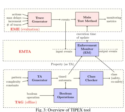
Fig. 3: Overview of TIPEX tool
TiPEX is a tool of 1,200 LLOC in Python and consists of three modules (see Fig. 3). Module Enforcement Monitor from Timed Automata (EMTA) consists in an implemen-tation of the enforcement algorithms described in [1]. Module Enforcement Monitor Evaluation(EME) is a test harness for the performance of enforcement monitors, with functionalities such as a trace generator. Module Timed Automata Generator (TAG) pro-vides functionalities such as generating and composing TAs (which can be also used in other contexts than enforcement monitoring). Module TAG provides a TA (defining the
4
Regular properties are the ones that can be defined by TA. Safety (resp. co-safety) properties are the prefix-closed (resp. extension-closed) languages. See [1] for more details.
requirement) to module EMTA, and information such as the class to which the timed automaton belongs. The functionalities of this module are used offline (i.e., prior to monitoring). TAG manipulates TAs described in UPPAAL [5] model written in XML. TAG and EMTA make use of the UPPAAL pyuppaal and DBM libraries, respectively.5
2.1 Module EMTA Enforcement Monitor Dump Process Store Process Shared Memory Memory Output Input Fig. 4: Implementing an EM
Module EMTA is the core functionality. It implements enforcement monitors by two concurrently running processes called as store and dump, communicating via shared memory as shown in Fig. 4. The shared memory contains the corrected se-quence that can be released as output. The memory is realized as a queue, shared by the processes store and dump, where process store adds events with corrected delays. Pro-cess dump reads events stored in the shared memory and releases them as output after the required amount of time. Process store also makes use of another internal memory (not shared with any other process), to store the events that cannot be yet corrected (to satisfy the property).
EMTA takes as input a TA and one trace. The most important part of module EMTA is the store process which computes optimal output delays for input events by exploring the TA. This computation relies on function Update. The dump process of monitors are algorithmically simple and lightweight from a computational point of view.
Algorithm 1 Update(σmc, q) allPaths ← computeReach(σmc, q) accPaths ← getAccPaths(allPaths) if accpaths = {} then return(ff, σmc) else σmc0 ← getOptimalWord(accPaths, σmc) return(tt, σ0mc) end if
Function Update (see Algo. 1) checks if an accepting state is reachable in the TA from the current state q, upon a delayed version of the sequence of events σmc
provided as input. In case if an accept-ing state is reachable, then it computes optimal delays. It returns a timed word of same length as σmc and a Boolean
indicating the result of this reachability analysis. Function computeReach com-putes all the reachable paths from the current state q upon events in σmc. These paths
are computed using forward analysis, zone abstraction, and operations on zones such as the resetting of clocks and intersection of guards [4]. Function getAccPaths takes all the paths returned by computeReach and returns a subset of them that end in an ac-cepting location. A path is acac-cepting if the location in its last state belongs to the set of accepting locations of the input TA. Function getOptimalWord takes all the accepting paths and a sequence σmcand computes optimal delays for events in σmc. This function
first computes an optimal delay for each event, for all accepting paths. Finally, it picks a path among the set of accepting paths whose sum of delays is minimal, and returns it as the result. If the set of accepting paths is empty, then function Update returns ff and σmc. Otherwise, it returns tt and the optimal word computed using getOptimalWord.
5
The UPPAAL libraries are provided by Aalborg Univ. at http://people.cs.aau.dk/ ˜adavid/python/.
We now briefly describe the implementation of process store. It first parses an input model and performs the necessary initialization. As seen in Sec. 1, an EM may not output events immediately after they are received. Consequently, process store also uses an internal memory (σmc) to store events. Each event (t, a) of the trace in order is
appended to the internal memory, and function Update is invoked, with the current state information and the events in the internal memory (σmc·(t, a)). If function Update
returns ff, then the monitor waits for the next event. If function Update returns tt and σ0mc, σmc0 is added to the shared memory (since it contributes to a correct sequence
and can be released as output). Before continuing with the next event, the process store updates the current state information, and internal memory.
2.2 Module EME
Module EME is a test harness of 150 LLOC to: i) validate through experiments the architecture and feasibility of enforcement monitoring, and ii) measure and analyze the performance of function Update of process store. The architecture of module EME is depicted in Fig. 3.
Module Trace Generator takes as input the alphabet of actions, the range of possible delays between actions, the desired number of traces, and the increment in length per trace. For example, if the increment in length per trace is 100, then the first trace is of length 100 and the second trace of length 200 and so on. For each event, module Trace Generator picks an action (from the set of possible actions), and a random delay (from the set of possible delays) using methods from the Python random module.
Module Main Test Method uses module Trace Generator to obtain a set of input traces to test module EM. It sends each sequence to the EM, and keeps track of the re-sult returned by the EM for each trace. Module EM takes as input a property (defined as a TA) and one trace, and returns the total execution time of function Update to process the given input trace. In process store, the execution time of Update is measured. Pro-cess store keeps track of the total time of Update, by adding the time measured after each event to the total time, which is returned as a result of invoking process store.
2.3 Module TAG
Motivations.TAG facilitates the translation of informal requirements into formal models by automating the process of generating TAs. Using TAG, one can generate several (meaningful) TAs of some pattern, with varying complexity which can be used as input models for testing EMs. Note, TiPEX can be also used with manually generated TAs.
Consider the requirement “There cannot be more than 100 requests in every 10 t.u.”. The TA defining this requirement has more than 100 locations and associated tran-sitions, and manually modeling it (for example using a graphical editor) is tedious and time consuming. Using TAG, the corresponding TA can be obtained almost instantly, just by providing some pattern, time constraint, and actions. TAG also implements the algorithms for the composition of TAs using Boolean operations (defined in [3,1]).
Figure 3 presents the architecture of TAG. Note that the modules inside TAG are loosely coupled: each module can be used independently, and can be easily extended. In the following, we detail each sub-module.
Generating Basic Timed Automata. Module TA Generator generates TAs based on some parameters: the pattern specifying the form of the TA among those defined in [6];
some complexity constant specifying the number of transitions and locations, the max-imal constant in guards, and some action alphabets.
Supported patterns.Currently, the tool supports generation of automata for the require-ments of the following forms (see [6]):
- Absence: In every consecutive time interval of TIME CONSTRAINT CONSTANT t.u., there are no more than COMPLEXITY CONSTANT actions from ACTION SET1. - Precedence with a delay: A sequence of COMPLEXITY CONSTANT actions from ACTION SET1enable actions belonging to ACTION SET2 after a delay of at least TIME CONSTRAINT CONSTANTt.u.
- Timed bounded existence: There should be COMPLEXITY CONSTANT consecutive actions belonging to ACTION SET1 which should be immediately followed by an action from ACTION SET2 within TIME CONSTRAINT CONSTANT time units. Composing Timed Automata. Module Boolean Operations builds a TA by compos-ing two input TAs uscompos-ing Boolean operations (see Fig. 3). All boolean operations are supported. In particular, operations Union and Intersection are performed by building the synchronous product of the two input TAs, where, in the resulting automaton, each location is a pair, and the guards are the conjunctions of the guards in the input TA. For operation Union, accepting locations are the pairs where at least one location is accepting in the input TAs, and for Intersection operation, both the locations in the corresponding input TAs are accepting. See [3] for formal details.
Identifying the Class of a Timed Automaton. Module Class Checker takes as input a TA and determines the class of the property it defines:6 safety(resp. co-safety) if the constraints of a safety (resp. co-safety) TA are satisfied, and “other” otherwise. With the class information, one can use simplified enforcement algorithms (see Sec. 3).
3
Performance Evaluation
We focus on the performance evaluation of function Update, the most computa-tionally intensive step as discussed in Sec. 2.1. Experiments were conducted on an Intel Core i7-2720QM at 2.20GHz CPU, with 4 GB RAM, and running on Ubuntu 12.04 LTS. The reported numbers are mean values over 10 runs and are represented in sec-onds. To compute the average values, 10 runs turned out to be sufficient because, for all metrics, with 95 % confidence, the measurement error was less than 1 %.
The considered properties follow different patterns [6], and belong to different classes. They are recognized by one-clock TA since this is a current limitation of our implementation. We however expect the trends exposed in the following to be similar when the complexity of automata grows.
- Property ϕsis a safety property expressing that “There should be a delay of at least
5 t.u. between any two request actions”.
- Property ϕcsis a co-safety property expressing that “A request should be immediately
followed by a grant, and there should be a delay of at least6 t.u between them”.
6
A TA defining a safety (resp. a co-safety) property is said to be a safety (resp. a co-safety) TA. In a safety (resp. co-safety) TA, transitions are not allowed from non-accepting (resp. accepting) to accepting (resp. non-accepting) locations. For formal details, see [1].
- Property ϕreis a regular property, but neither a safety nor a co-safety property, and
expresses that “Resource grant and release should alternate. After a grant, a request should occur between 15 to 20 t.u”.
Table 1: Performance analysis.
ϕs ϕre ϕcs |tr| t Update (sec) |tr| t Update (sec) |tr| t Update (sec) 10, 000 9.895 10,000 16.354 100 3.402 20, 000 20.323 20,000 32.323 200 13.583 30, 000 29.722 30,000 48.902 300 29.846 40, 000 40.007 40,000 65.908 400 53.192 50, 000 49.869 50,000 83.545 500 82.342 60, 000 59.713 60,000 99.088 600 120.931 70, 000 72.494 70,000 117.852 700 169.233
Results and analysis.Results of the per-formance analysis for ϕs, ϕcs, and ϕre
are reported in Table 1. Entry |tr| (resp. t Update) indicates the length of the considered traces (resp. the total execu-tion time of funcexecu-tion Update).
As expected, for the safety property (ϕs), we can observe that t Update
increases linearly with the length of the input trace. Moreover, the time taken per call to Update (which is
t Update/|tr|) does not depend on the length of the trace. This behavior is as expected
for a safety property: function Update is always called with only one event which is read as input (the internal buffer σmc remains empty). Consequently, the state of the
TA is updated after each event, and after receiving a new event, the possible transitions leading to a good state from the current state are explored.
For the co-safety property (ϕcs), the considered input traces are generated in such a
way that they can be corrected only upon the last event. Notice that t Update is now quadratic. For the considered input traces, this behavior is as expected for a co-safety property because for an input sequence of length |tr|, function Update is invoked |tr| times, starting with a sequence of length 1 that is incremented by 1 in each iteration.
For the regular property (ϕre), the considered input traces are generated in such
a way that it can be corrected every two events. Consequently, function Update is invoked with either one or two events. For the considered input traces, t Update is linear in |tr|, and thus the time taken per call to Update (which ist Update/|tr|) does
not depend on the length of the trace. For input traces of same length, the value of t Update is higher for ϕrethan the value of t Update for ϕs. This stems from the fact
that, for a safety property, function Update is invoked only with one event.
Implementation of simplified algorithms for safety properties.As explained in [1], for safety properties, the internal memory is never used, since the decision of whether to output an event or not has to be taken when receiving it. Thus, the functional defini-tion can be simplified, and consequently the enforcement monitors and algorithm can be also simplified. The simplified algorithm is also implemented in TiPEX, and experi-ments were conduced using several safety properties (see [1] for details and evaluation results). From the results in [1], we can notice that for safety properties, using the sim-plified algorithm gives better performance. The time taken per call to Update reduces by around 0.2 milliseconds using the simplified algorithm.
Remark 1. More experimental results used to assess the influence of the size, class, and pattern of a property on the monitoring metrics are available in [1,7].
4
Summary and Discussion
TiPEX implements and assesses the enforcement monitoring algorithms for timed properties in [1]. It demonstrates the practical feasibility of our theoretical results.
TiPEX consists of 3 modules. Module EMTA consists of functionalities to synthe-size enforcement monitors from a TA, and module EME is a test harness for monitors. Module TAG consists of features to automatically generate TAs from some input data such as the actions, pattern, and time constraint constant. To the best of our knowledge, there is no available tool to help formalizing real-time requirements. As shown in the examples, the input data required by TAG can be easily inferred from the informal de-scription of a requirement. Moreover, TAG composes TAs using Boolean operations, and identifies the class of a given TA.
Assessing the performance of runtime enforcement monitors is crucial in a timed context as the time when an action happens influences satisfaction of the property. We also evaluated the performance of enforcement monitors for several properties, and con-sidering very long input executions. As our experiments in Sec. 3 show, the computation time of the monitor upon the reception of an event is relatively low. For example, for safety properties, one can see that, on the used experimental setup, the computation time of function Update is below 1ms. Moreover, given some average computation time per event and a property, one can determine easily whether the computation time is negligible or not for an application domain in consideration. By taking guards with constraints using integers above 0.1s, one can see that the computation time can be neg-ligible in some sense as the impact on the guard is below 1%, and makes the overhead of enforcement monitoring acceptable.
For co-safety and regular properties, the computation time of function Update de-pends on the property and the input trace. For example, for a co-safety property with a loop in a non-accepting location, the execution time of Update depends on the length of the minimal prefix of the input sequence allowing to reach an accepting state.
Finally, note that while the monitoring algorithm implemented in EME is used with traces, it is an online algorithm. To use TiPEX within a system for online runtime en-forcement, one needs to define the implementation of the delaying of an action in the monitored system by, for instance, suspending the thread performing the delayed action.
References
1. Pinisetty, S., Falcone, Y., J´eron, T., Marchand, H., Rollet, A., Nguena Timo, O.: Runtime enforcement of timed properties revisited. Formal Methods in System Design 45 (2014) 381– 422
2. Falcone, Y., Havelund, K., Reger, G.: A tutorial on runtime verification. In: Engineering Dependable Software Systems. Volume 34. IOS Press (2013) 141–175
3. Alur, R., Dill, D.L.: A theory of timed automata. Theoretical Computer Science 126 (1994) 183–235
4. Bengtsson, J., Yi, W.: Timed automata: Semantics, algorithms and tools. In: Proceedings of the 4th Advanced Course on Petri Nets - Lecture Notes on Concurrency and Petri Nets. Volume 3098 of LNCS., Springer (2003) 87–124
5. Larsen, K.G., Pettersson, P., Yi, W.: UPPAAL in a nutshell. International Journal on Software Tools for Technology Transfer 1 (1997) 134–152
6. Gruhn, V., Laue, R.: Patterns for timed property specifications. Electronic Notes in Theoretical Computer Science 153 (2006) 117–133
7. S. Pinisetty et al.: TiPEX website. http://srinivaspinisetty.github.io/ Timed-Enforcement-Tools/(2015)
A
Demonstration of TiPEX
We illustrate the features of TiPEX discussed in the paper via some examples. All the source files with examples, prerequisites, and some documentation are available at:
http:
//srinivaspinisetty.github.io/Timed-Enforcement-Tools/ A.1 Modules EMTA and EME
In the following subsections, we describe how to test the input-output behavior of an enforcement monitor, and how to collect performance data for a property.
Testing the Behavior of an Enforcement Monitor We present how the input-output behavior of enforcement monitors for some properties is tested. We consider three ex-ample properties (used in Sec. 3). We also provide the TAs defining these properties in UPPAAL format (.xml files) inside the source folder.
– Example Safety.xml defines a safety property expressing that a safety property expressing that “There should be a delay of at least 5 t.u. between any two request actions”.
– Example CoSafety.xml defines a co-safety property expressing that “A request should be immediately followed by a grant, and there should be a delay of at least 7 t.u. between them”.
– Example Response.xml defines a regular property, and expresses that “Resource grant and release should alternate. After a grant, a request should occur between 15 to 20 t.u.”. Note that this property is neither a safety nor a co-safety property. To test the functionality, with these properties for some input traces, simply run the test script testFunctionality.py (available inside the source folder). For each property, the input trace provided and the output of the EM is printed on the console. On the console, we can observe that for each property, for the provided input, the output satisfies the property (soundness) and the other constraints (transparency, optimality). Collecting Performance Data We explain via an example how the main test method is invoked via Python command line to collect performance data for a property (see Fig. 5). The steps are the following:
– Import the MainTest module.
– Specify the property by indicating its path.“Example Safety.xml” is the property in this example, which is a UPPAAL model stored as “.xml”.
– Specify the accepting locations in the input TA. For instance, by typing “accLoc=[‘S1’, ‘S2’]”, one specifies that the set of accepting locations in the input TA is {S1, S2}. – Specify the possible actions. For instance by typing “actions = [‘a’, ’r’]” one
spec-ifies that the set of actions is {a, r}. – Define the range of possible delays.
– Invoke method testStoreProcess in module MainTest, providing the follow-ing arguments in order: property, acceptfollow-ing locations, actions, delays, # traces incr.
Fig. 5: Collecting performance data.
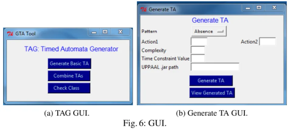
(a) TAG GUI. (b) Generate TA GUI.
Fig. 6: GUI.
“#traces” is the number of traces used for testing (3 in the example above), each trace varying is length, and “incr” is the increment in length per trace (1,000 in the example above). As shown in Fig. 5, a list of triples (trace length, total execution time of the Update function, average time per call of the Update function) is returned as the result.
A.2 Module TAG
Module TAG has a basic GUI. The following lines demonstrates how to launch the GUI via Python command line.
– Browse to the folder containing the source code.
– Execute the script GUI TAG Tool.py entering the following line in the command prompt python GUI TAG Tool.py.
– A GUI will be launched (shown in Fig. 6a), using which the user can select to generate a basic TA, or to combine TAs, or to check the class of a TA.
We demonstrate how to use each feature via an example.
Generating Basic Timed Automata We present some TAs generated using module TA Generator. Clicking “Generate Basic TA” launches the GUI shown in Fig. 6b. To generate a TA defining the requirement “In any time interval of 10 t.u., there cannot be 3 or more a actions”, the values of the input parameters provided the tool are:
NAcc L1 L2 L0 x<5 x>=5 L3 b? a? b? b? a? b? b? a? a? a? b?
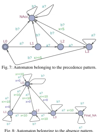
Fig. 7: Automaton belonging to the precedence pattern.
x<10 x>=10 L0 L1 L2 x>=10 x<10 x<10 x<10 x>=10 x>=10 L3 x=0 Final_NA x=0 x=0 x=0 b? a? a? b? a? a? a? a? a? b? b? a? b? a?
Fig. 8: Automaton belonging to the absence pattern.
– COMPLEXITY CONSTANT = 3, – TIME CONSTRAINT CONSTANT = 10, – ACTION1 = a, and ACTION2 = b.
Figure 8 shows the representation in UPPAAL. In this TA, L0 is initial location, {L0, L1, L2, L3} is the set of accepting locations, and the only non-accepting location is Fi-nal NA. In L0, upon action a, if the value of clock x ≥ 10, then the clock x is reset and the TA remains in the same location. We can see that the TA moves to a non-accepting (trap location) Final NA upon 3 a actions within 10 time units. To generate a TA defin-ing the requirement “A sequence of 3 a actions enables action b after a delay of at least 5 t.u.”, the values of the input parameters provided to the tool are:
– PATTERN = precedence, – COMPLEXITY CONSTANT = 3, – TIME CONSTRAINT CONSTANT = 5, – ACTION1 = a, and ACTION2 = b.
Figure 7 shows its representation in UPPAAL tool. In this TA, L0 is the initial location, {L0, L1, L2, L3} is the set of accepting locations, and the only non-accepting location is NAcc. We can see that from locations L0, L1, and L2, if a b action occurs then the TA moves to the trap state, since 3 preceding a actions are missing.
Fig. 9: Combine TA GUI.
Composing Timed Automata Clicking “Combine TAs” launches the GUI shown in Fig. 9. Clicking “Select File” button allows the user to select a input UPPAAL model. The input UPPAAL model (stored as .xml) selected by the user, should contain two input TAs (defined as two different templates). Note that in the input TAs, names of accepting locations should be prefixed by “Final”. The user should select an operation. The resulting TA will be written as another template in the UPPAAL model file given as input by the user.
Let us now see an example of the resulting TA obtained after combining two TAs using the Boolean Operations functionality. The two input TAs are shown in Fig. 10a and Fig. 10b. Figure 10c shows the resulting TA after combining the two input TAs using Union operation.
Final x>=5 x<5 IL b? a? b? a? b? (a) TA1 Final y>=10 y<10 IL a? b? a? a? b? (b) TA2 y>=10 y<10 x>=5 x>=5 y>=10 x<5 x<5 y<10 Final2 ILIL Final1 Final0 a? a? b? a? b? b? b? b? b? a? a? a?
(c) Union of TA1 and TA2