HAL Id: hal-02994201
https://hal.archives-ouvertes.fr/hal-02994201
Submitted on 7 Nov 2020
HAL is a multi-disciplinary open access
archive for the deposit and dissemination of
sci-entific research documents, whether they are
pub-lished or not. The documents may come from
teaching and research institutions in France or
abroad, or from public or private research centers.
L’archive ouverte pluridisciplinaire HAL, est
destinée au dépôt et à la diffusion de documents
scientifiques de niveau recherche, publiés ou non,
émanant des établissements d’enseignement et de
recherche français ou étrangers, des laboratoires
publics ou privés.
Shaking Force Balancing of the Delta Robot
Damien Chablat, Jing Geng, Vigen Arakelian
To cite this version:
Damien Chablat, Jing Geng, Vigen Arakelian. Shaking Force Balancing of the Delta Robot. The
ASME 2020 International Design Engineering Technical Conferences & Computers and Information
in Engineering Conference, IDETC/CIE 2020, Aug 2020, Saint Louis, United States. �hal-02994201�
Proceedings of the ASME 2020 International Design Engineering Technical Conferences and Computers and Information in Engineering Conference IDETC/CIE2020 August 16-19, 2020, ST. Louis, MO, USA
DETC2020-16067
SHAKING FORCE BALANCING OF THE DELTA ROBOT
Jing Geng1,2, Vigen Arakelian1,2, Damien Chablat1
1
LS2N UMR 6004, 1 rue de la Noë, BP 92101, F-44321 Nantes, France
2
Mecaproce / INSA-Rennes
20 av. des Buttes de Coesmes, CS 70839, F-35708 Rennes, France
[email protected] & [email protected]
ABSTRACT
The paper deals with the shaking force balancing of the DELTA robot. The balancing of the shaking force of the DELTA robot is carried out through the center of mass acceleration minimization. The trajectories of the total mass center of moving links are defined as straight lines between the initial and final positions of the platform. Then, the motion between these positions are parameterized with “bang-bang” motion profiles. Such a motion generation allows the reduction of the maximal value of the center of mass acceleration and, consequently, leads to the reduction in the shaking force. A main advantage of this method is its simplicity and versatility. It is carried out without any modification of mass redistribution of the initial robot structure, i.e. without adding counterweights. In the case of changing trajectories or payloads, it is just necessary to provide the initial and final positions of the platform, calculate the input parameters according to the proposed method and implemented them in the robot control system. Numerical simulations illustrate the efficiency of the suggested approach.
1. INTRODUCTION
The DELTA robot (Fig. l) has been developed by Prof. Reymond Clavel [1], [2] as a three-degree-of-freedom parallel robot, dedicated to high-speed applications of lightweight objects in the microengineering, electronic, food and pharmaceutical industries. By adding a supplementary independent rotation, it has been transformed to a robot for pick-and-place applications. The basic idea behind the Delta
robot design is the use of parallelograms. A parallelogram allows an output link to remain at a fixed orientation with respect to an input link. The use of three such parallelograms restrains completely the orientation of the mobile platform, which remains only with three purely translational degrees of freedom.
The main benefit of Delta robots is that the heavy motors are fixed on the frame, allowing the moving parts of the robot to be very light. In the modern design of Delta robots, the motion is being translated down through carbon fiber arms, where there is far less mass being moved.
Many researchers have extensively studied the workspace [3], [4], kinematics [5]-[8], statics [9], [10], dynamics [11], [12], control [14]-[16], calibration [17], [18] of the DELTA robot.
The optimal balancing of gravitational forces of the DELTA robot has also been investigated. In [19], [20], the elastic elements have been used for gravity compensation. In [21], the gravity compensation has been involved by connecting an actuated balancing system to the initial DELTA structure, which generates a vertical force applied to the robot platform.
However due to large accelerations, the dynamic loads of the moving links and platform are the source of vibrations, which can degrade robot performance. To reduce these vibrations, mostly the Delta robot is mounted on a large and massive frame.
FIGURE 1: THE BASIC VERSION OF THE DELTA ROBOT
It should be noted that the shaking force and shaking moment balancing of parallel robots is a complicated problem because it can only be achieved either by an unavoidable increase of the total mass of moving links or by a considerably more complicated design of the initial parallel mechanism [22]. In [23], it has been shown that fully shaking force balancing of the DELTA robot can be achieved by adding three counter-masses with two additional links and the complete shaking moment balancing can be achieved by active actuation of three additional rotating links.
In [24] has been developed a new balancing approach based on the optimal trajectory planning of the common center of mass of the manipulator. The aim of the developed balancing method consists in the fact that the manipulator is controlled not by applying end-effector trajectories but by planning the displacements of the total mass center of moving links. The trajectories of the total mass center of the manipulator are sated as a straight line between the initial and final positions of the end-effector. Then, the motion between these positions is parameterized with “bang-bang” motion profile. It allows the reduction of the maximal value of the center of mass acceleration and, consequently, leads to the reduction in the shaking force. This method found further development in [25]-[31].
The present paper deals with the shaking force balancing of the DELTA robot via optimal acceleration control of the common center of masstaking into account the payload. Note that during such balancing, the counterweights are not added to the robot links, and the reduction of inertial forces is carried out by optimal trajectory and acceleration generation of the common center of mass of the DELTA robot.
2. PROBLEM FORMULATION
The kinematic architecture of the Delta robot is shown in Figure 1. The platform is linked with the base by three identical kinematic chains, each of which consists of two links. The Cartesian coordinate system Oxyz is located in the mass center of the base O with the y-axis normal to OA and the z-3
axis vertical to the surfaceA A A1 2 3. The joints that connect the base to the three chains are denoted as A ii( =1, 2, 3), Aiare evenly distributed on the circle with O as the center and R as the radius (see in Figure 2); the joints between the moving platform and the three legs are denoted as C ii( =1, 2, 3), Ci are
evenly distributed on the circle with P as the center and r as the radius. It should be noted that OAiCPC ii( =1, 2, 3). The angles between OA ii( =1, 2, 3)and x-axis are denoted as θi (see
in Figure 3).
FIGURE 2: PARAMETERS OF THE DELTA ROBOT
FIGURE 3: ANGLES θ =i(i 1, 2, 3) IN THE DELTA ROBOT
For each chain, the two links are connected by joints
( 1, 2, 3)
i
B i= . The output axis ( , , )P x y z is the axis of the
platform. The lengths of links are denoted as
( 1, 2, 3)
i i
a=A B i= , b=B C ii i( =1, 2, 3). The masses of the link ( 1, 2, 3)
i i
A B i= is denoted as m1; The masses of the link ( 1, 2, 3)
i i
B C i= is denoted as m ; The masses of the platform is 2
denoted as m . P
The coordinates of the common center of mass of the DELTA robot can be written as:
xS m xi Si m
yS m yi Si m =
∑
(2) zS m zi Si m =∑
(3) where, mi is mass of the leg i, xSi,ySi,zSi are the coordinates of its center mass, m is the total mass of moving links.Thus, S(t) with coordinates xS,y zS, S presents the trajectory of the common center of mass of the DELTA robot.
Now let us determine the shaking force of the robot:
2 sh 2 S(t) F md ms dt = = (4) where, s is the acceleration of the common center of mass.
The shaking force balancing via mass redistribution consists in adding counterweights [22] in order to keep the total mass center of moving links stationary. In this case, s=0 for any configuration of the robot. As a result, the shaking force is cancelled. It is obvious that the adding of supplementary masses as counterweights is not desirable because it leads to the increase of the total mass, of the overall size of the robot and the shaking moment. Therefore, it is proposed to minimize the shaking force via reduction of the total mass center acceleration: ( ) max s min s t → (5)
i.e. to apply an optimal control of the total mass center of moving links that allows one to reduce the maximal value of its acceleration.
For this purpose, let us consider the control of the Delta robot through of its common center of mass. To ensure it, let us assume that the center of mass moves along a straight line between its initial and final positions. Thus, the motion profile used on this path will define the variations of shaking forces. For the similar displacement of the total center of mass S(t)
with the same initial and final positions, the maximal value of the acceleration changes following the motion profile [32]: for quartic polynomial profile 2
max 10 3
a = S t and for “bang-bang” profile 2
max 4
a = S t . It means the application of bang-bang law theoretically brings about a reduction of 31% of the maximal value of the acceleration. Hence, to minimize the maximum value of the acceleration of the total mass center and, consequently, shaking forces, the “bang-bang” profile should be used. Thus, by reducing the acceleration of the common center of mass of the Delta robot, a decrease in its shaking forces should be achieved.
To accomplish the shaking force balancing through the above described technique, it is necessary to consider the
relationship between the input parameters and the center of mass position of the Delta robot.
3. SHAKING FORCE BALANCING OF THE DELTA ROBOT
In order to control the robot according to the method described above, it is necessary to establish the relationship between the displacement of the total center of mass S(t) and the input parameters α ( 1,2,3)i i= (see in Figure 2), i.e. for the given position and the law of motion of the common center of mass of the robot determine its input displacements. Then, by means of the obtained input parameters via forward kinematics determine the position of the platform P( , , )x y z .
For this purpose, let us establish the relationship between the common center of mass of the robot and its input parameters. Let us start this issue with the initial and final positions P( , , )x y z of the platform P ( ,i x y zi i, )i and
f
P (xf,yf,zf). So, by inverse kinematics, the input angles
corresponding to these positions will be determined: αi and
f
α . The corresponding values of the common center of mass of the robot can also be found: Si(xSi,ySi,zSi) and S (f xSf, ySf,zSf)
.
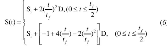
The displacement of the total center of mass S(t) moving through a straight line can be expressed via D (d d dx, y, z) [32]. Subsequently, the trajectory planning by “bang-bang” profile with the time interval tf can be established:
2 i 2 i S 2( ) D, (0 ) 2 S(t) S 1 4( ) 2( ) D, (0 ) 2 f f f f f t t t t t t t t t t + ≤ ≤ = + − + − ≤ ≤ (6)
Let us now consider the relationship between S(t) and the input displacementsα ( 1,2,3)i i= .
FIGURE 4: THE DELTA ROBOT WITH SUBSTITUTED POINT MASSES AND ITS COMMON CENTER OF MASS
Firstly, the masses of links will be substituted by point masses located at joint centers A B Ci, i, i (Figure 4) [22].
For leg i (i=1,2,3), the coordinates of the corresponding
joints can be expressed as following: Ai
(
Rcos , sinθi R θi, 0)
,i
B [(R+acosαi) cos , (θi R+acosαi) sinθi,−asinαi],
(
)
i
C x+rcos ,θi y+rsinθi,z .
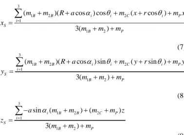
So, the coordinates of the common canter of mass of the DELTA robot can be written as:
3
1 2 2
1
1 2
( )( cos ) cos ( cos )
3( ) B B i i C i P i S B P m m R a m x r m x x m m m α θ θ = + + + + + = + +
∑
(7) 3 1 2 2 1 1 2( )( cos ) sin ( sin )
3( ) B B i i C i P i S B P m m R a m y r m y y m m m α θ θ = + + + + + = + +
∑
(8) 3 1 2 2 1 1 2 sin ( ) ( ) 3( ) i B B C P i S B P a m m m m z z m m m α = − + + + = + +∑
(9) where, mP =mPl is the mass of the platform.Then, three equations should be added to these equations, which present relations between input angles α ( 1,2,3)i i= and output coordinates P( , , )x y z : 2 cosa αi(Qi−λ)+2 sina αiz+Ci+2λQi =0 (10) where i=1, 2, 3, Ci =b2−x2−y2−z2−λ2−a2, λ= − , R r cos sin i i i Q =x θ +y θ .
Thus, from the resulting system of nonlinear equations (7), (8), (9), (10), the input angles α ( 1,2,3)i i= will be determined. 4. SHAKING FORCE BALANCING OF THE DELTA
ROBOT TAKING INPUT THE VARYING PAYLOAD A significant advantage of this method is that it facilitates the shaking force balancing of robots taking into account the varying payload. It is obvious that the DELTA robot cycles are carried out with payload and without it. Therefore, dynamic loads will be different for these two types of cycle. Due to the high payload to moving mass ratio of the DELTA robot, the influence of the payload on the balance of the shaking force should be stronger. Thus, it is desirable that the varying payload will be included in the state of the DELTA robot balancing. However, an adapting shaking force balancing is a rather difficult task [33]. It can be accomplished by reconfiguration of mass position [34]-[37], by reconfiguration of joint position
[38], by changing the counterweigh value [38] or by adding additional degrees of freedom [39], [40].
In our case, this is quite simple: it is enough to include the mass of the payload in eq. (7)-(9) together with the mass of the platform, i.e. in this case: mP =mPl+mPayload. Obviously, this will change the values of the coordinates of the common center of mass, consequently, the input parameters α ( 1,2,3)i i= . Thus, the input parameters with payload or without it will be different. In the same way, one can determine the input parameters when the payload changes.
5. NUMERICAL ILLUSTRATIVE EXAMPLE WITH SIMULATION RESULTS
For CAD simulations, the following parameters of the Delta robot are applied: a= A Bi i =0.75 (m i=1, 2, 3),
0.95 ( 1, 2, 3)
i i
b=B C = m i= , m1 =2.3kg, m2 =5.2kg,
3
P
m = kg. The trajectory of the platform is given by initial and final positions P 0, 0, 1i
(
−)
and P 0.3, 0.2, 0.9f(
−)
, from which the position of the common center mass Si(
0, 0, −0.789)
,(
)
f 0.191, 0.1
S 79, 0.707− and the input angles
(
)
i 0.912, 0.912, 0 912
α − − − . , αf
(
−0.730, 1.336, 0 667− − .)
aredetermined.
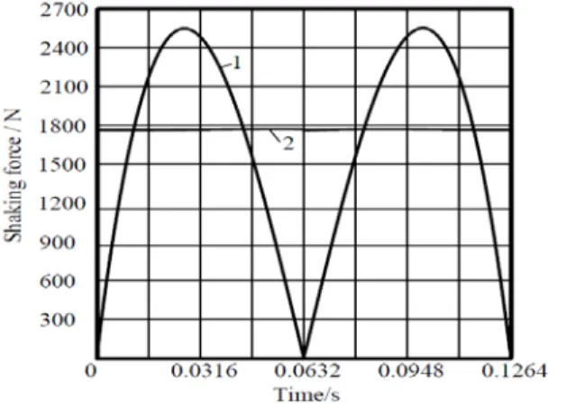
FIGURE 5: VARIATIONS OF SHAKING FORCES FOR TWO STUDIED CASES
FIGURE 6: VARIATIONS OF SHAKING MOMENTS FOR TWO STUDIED CASES
The simulation results have been carried out for
0.1264
f
t = s. Figures - 6 show the variations of shaking forces and the shaking moments for two studied cases: 1) the displacement of the platform of the DELTA robot by the straight line with fifth order polynomial profile and 2) the generation of the motion via the displacement of the robot center mass by “bang-bang” profile. The obtained results show that the shaking force has been reduced up to 30.5% (Figure 5). The comparison of two studied cases shows that the shaking moment of the “bang-bang” profile has a reduction of 27.2% (Figure 6).
FIGURE 7: VARIATIONS OF SHAKING FORCES OF THE DELTA ROBOT WITH PAYLOAD FOR TWO STUDIED CASES
Now, let us consider that the same trajectory should be carried out with a payload of 4kg. Considering the shaking force minimization with payload as described above, the shaking force has been reduced up to 30.5% (Figure 7).
6. CONCLUSIONS
In this paper, the shaking force balancing of the DELTA robot has been discussed. The aim of this technique consists in the fact that the DELTA robot is controlled not by applying platform trajectories but by planning the displacements of the total mass centre of the moving links. The trajectory of the total mass centre of moving links is defined as a straight line. Then, it is parameterized with “bang-bang” profile. It allows the reduction of the maximum value of the centre of mass acceleration and, consequently, the reduction in the shaking force. It has also been shown that it is easy to take into account the varying payload with such balancing technique. Although such balancing does not lead to a complete cancellation of the shaking force, but it allows one to significantly reduce it without changing the basic design of the robot.
The suggested technique has been illustrated through CAD simulations. The results obtained via ADAMS simulations showed that a reduction in the maximum value of the shaking force of 30.5% has been obtained. It has also been shown that ignorance of the payload leads to the deterioration of the
balancing. Taking payload into account allowed increasing the efficiency of balancing.
It appears that the suggested solution of shaking force balancing of the DELTA robot can be attractive for industrial robot applications because it can easily be implemented in practice.
REFERENCES
[1] Clavel, R., 1988, “DELTA, a fast robot with parallel geometry”, Proceedings of 18th Int. Symp. on Industrial Robot, Lausanne, Switzerland, pp. 91-100.
[2] Clavel, R., 1991, “Conception d’un robot parallèle rapide à 4 degrés de liberté”, PhD dissertation, Lausanne, EPFL. [3] Laribi, M.A., Romdhane, L., Zeghloul, S., 2007,
“Analysis and dimensional synthesis of the DELTA robot for a prescribed workspace”, Mech. and Mach. Theory, Vol. 42, pp. 859–870.
[4] Jha, R., Chablat, D., Baron L., Rouillier, F., Moroz, G., 2018, “Workspace, joint space and singularities of a family of delta-like robot”, Mech. and Mach. Theory, Vol. 127, pp. 73-95.
[5] Pierrot, F., Reynaud, C., Fournier, A., 1990, “DELTA: a simple and efficient parallel robot”, Robotica, vol. 8, pp. 105-109.
[6] Pierrot, F., Daucher, P., Fournier, A., 1991, “Fast parallel robots”, Journal of Robotic Systems, Vol. 8, pp. 829-840. [7] Stock, M, Miller, K., 2003, “Optimal kinematic design of
spatial parallel manipulators: application to linear delta robot”, Trans. ASME, Journal of Mechanical Design, vol. 125, pp. 292-301.
[8] Brinker, J., Corves, B., Takeda, Y., 2018, “Kinematic performance evaluation of high-speed Delta parallel robots based on motion/force transmission indices”, Mech. and Mach. Theory, Vol. 125, pp. 111–125.
[9] Briot, S., Baradat, C., Guegan, S., Arakelian, V., 2005, “Torque minimization of the Delta parallel robot”, Proceedings of CANCAM 2005, Montréal, Canada. Hal-00451956.
[10] Briot, S., Baradat, C., Guegan, S., Arakelian, V., 2007, “Contribution to the Mechanical Behavior Improvement of the Robotic Navigation Device Surgiscope®”, Proceedings of ASME 2007 IDETC/CIE, Las Vegas, Nevada, USA, pp. 653-661.
[11] Miller, K., Claver, R., 1992, “The Lagrange-based model of Delta-4 robot dynamics”, Robotersysteme, Vol. 8, pp. 49-54.
[12] Staicu, St., Carp-Ciocardia, D.C., 2003, “Dynamic analysis of Clavel's Delta parallel robot”, Proceedings of ICRA’2003, Taipei, Taiwan, pp. 4116-4121.
[13] Brinker, J., Corves, B., Wahle, W., 2015, “A Comparative Study of Inverse Dynamics based on Clavel’s Delta robot”, Proceedings of 14th IFToMM World Congress, Taipei, Taiwan.
[14] Codourey, A., Clavel, R., Burckhardt, C.W., 1992, “Control algorithm and controller for the direct drive delta
robot”, Proceedings of the 3rd IFAC/IFIP/IMACS Symposium, Vienna, Austria, pp. 543-549.
[15] Miller, K., Stevens, B.S., 1995, “Modeling of dynamics and model-based control of DELTA diret-drive parallel robot”, Journal of Robotics and Mechatronics, Vol. 7, pp. 344-352.
[16] Rey, L., Clavel, R., 1999, “The Delta Parallel Robot”, Parallel Kinematic Machines, pp 401-417.
[17] Vischer, P., Clavel, R., 1998, “Kinematic calibration of the parallel Delta robot”, Robotica, Vol. 16, pp. 207-218. [18] Bai, P., Mei, J., Huang, Tian and Chetwynd, D. G., 2015,
“Kinematic calibration of Delta robot using distance measurements. Proceedings of the Institution of Mechanical Engineers, Part C: Journal of Mechanical Engineering Science, Vol. 230, pp. 414-424.
[19] Simionescu, I., Ciupitu, L., Ionita, L., 2015, “Static balancing with elastic systems of DELTA parallel robots”, Mech. and Mach. Theory, Vol. 87, pp. 150-162.
[20] Martinia, A., Troncossia, M., Carricato, M., Rivola, A., “Static balancing of a parallel kinematics machine with Linear-Delta architecture: theory, design and numerical investigation”, Mech. and Mach. Theory, Vol. 90, pp. 128-141.
[21] Baradat, C., Arakelian, V., Briot, S., Guegan, S., 2008, “Design and prototyping of a new balancing mechanism for spatial parallel manipulators”, Transactions of the ASME. Journal of Mechanical Design, Vol. 130.
[22] Arakelian, V., and Briot, S., 2015, “Balancing of linkages and robot manipulators. Advanced methods with illustrative examples”, Springer.
[23] Van der Wijk, V. Herder, J. L., 2009, “Dynamic Balancing of Clavel’s Delta Robot”, Computational Kinematics, Springer, pp. 315–322.
[24] Briot, S., Arakelian, V., Le Baron, J.-P., 2012, “Shaking force minimization of high-speed robots via center of mass acceleration control”, Mech. Mach. Theory, Vol. 57, pp. 1–12.
[25] Arakelian, V., 2016, “Design of partially balanced 5R planar manipulators with reduced center of mass acceleration (RCMA)”, Robot Design, Dynamics and Control, Springer, pp. 113-122.
[26] Arakelian, V., Geng, J., Le Baron, J.-P., 2017, “Synthesis of balanced 3-RRR planar parallel manipulators”, In Proc. of the 19th International Conference on Robotics and Computer Integrated Manufacturing (ICRCIM'2017), Prague, Czech Republic, Vol. 4, pp. 37-43.
[27] Arakelian, V., Geng, J., Fomin A., 2018, “Inertia forces minimization in planar parallel manipulators via optimal control”, Journal of Machinery Manufacture and Reliability, Vol. 47, pp. 303-309.
[28] Geng, J., Arakelian, V., 2019, “Design of partially balanced planar 5R symmetrical parallel manipulators via an optimal motion planning”, Proceedings of ECCOMAS 2019, Advances in Mechanism and Machine Science, Springer, pp. 2211-2220.
[29] Geng, J., Arakelian, V., 2020, “Partial shaking force balancing of 3-RRR parallel manipulators by optimal acceleration control of the total center of mass”, Proceedings of IFToMM 2019, Springer, pp. 375–382. [30] Arakelian, V., Geng, J., 2020, “Design of High-Speed
Manipulators via Optimal Control of the Acceleration of the Total Mass Center”, Advanced Technologies in Robotics and Intelligent Systems, Springer, vol. 80, pp. 299-307.
[31] Acevedo, M., Orvañanos-Guerrero, M. T., Velázquez, R., and Arakelian, V., 2020, “An alternative method for shaking force balancing of the 3RRR PPM through acceleration control of the center of mass”, Journal of Applied Sciences, pp. 1-19.
[32] Khalil, W., Dombre, E., 2002, “Modeling, identification and control of robots”, Hermes Sciences Europe.
[33] Jong, J.J., Herder, J. L., 2015, “A comparison between five principle strategies for adapting shaking force balance during varying payload”, Proceedings of the 14th World Congress in Mechanism and Machine Sciences, Taipei, Taiwan, 23-30 October, 2015.
[34] Arakelian, V., 1987, “Manipulator”, Patent SU1430258. [35] Chung, W.K., Cho, H.S., 1988, “On the dynamic
characteristics of a balance PUMA-760 robot”, IEEE Transaction on Industrial Electronics, 35(2), pp. 222–230. [36] Coelho, T.A.H., Yong, L., Alves, V.F.A., 2004,
“Decoupling of dynamic equations by means of adaptive balancing of 2-dof open-loop mechanisms”, Mech. and Mach. Theory, 39(8), pp. 871–881.
[37] Lecours A., Gosselin, C., 2010, “Reactionless two-degree-of-freedom planar parallel mechanism with variable payload”, Journal of Mechanisms and Robotics, 2(4):041010.
[38] Van der Wijk, V., Herder, J.L., 2009, “Force balancing of variable payload by active force-balanced reconfiguration of the mechanism”, Proceedings of ASME/IFToMM International Conference on Reconfigurable Mechanism and Robots, London, pp. 323–330.
[39] Yoshida, K., Hashizume K., Abiko, S., 2001, “Zero reaction maneuver: flight validation with ETS-VII space robot and extension to kinematically redundant arm. Procedings of the International Conference on Robotics and Automation, Seoul, Korea, pp. 441– 446.
[40] Van der Wijk, V., Herder, J.L., 2010, “Active dynamic balancing unit for controlled shaking force and shaking moment balancing”, Proceedings of the ASME 2010 IDETC/CIE, Montreal,Quebec, Canada.