HAL Id: hal-00966181
https://hal.archives-ouvertes.fr/hal-00966181
Submitted on 2 Jun 2014
HAL is a multi-disciplinary open access
archive for the deposit and dissemination of
sci-entific research documents, whether they are
pub-lished or not. The documents may come from
teaching and research institutions in France or
abroad, or from public or private research centers.
L’archive ouverte pluridisciplinaire HAL, est
destinée au dépôt et à la diffusion de documents
scientifiques de niveau recherche, publiés ou non,
émanant des établissements d’enseignement et de
recherche français ou étrangers, des laboratoires
publics ou privés.
Ultra-fast all-optical self-aware protection switching
based on a bistable laser diode
Yi An, Dragana Vukovic, Abel Lorences Riesgo, Geert Morthier, Christophe
Peucheret
To cite this version:
Yi An, Dragana Vukovic, Abel Lorences Riesgo, Geert Morthier, Christophe Peucheret. Ultra-fast
all-optical self-aware protection switching based on a bistable laser diode. Optical Fiber
Commu-nication Conference 2014 (OFC 2014), Mar 2014, San Francisco, CA, United States. pp.W2A.65,
�10.1364/OFC.2014.W2A.65�. �hal-00966181�
Ultra-Fast All-Optical Self-Aware Protection Switching
Based on a Bistable Laser Diode
Yi An1, Dragana Vukovic1, Abel Lorences Riesgo1, Geert Morthier2 and Christophe Peucheret1,3* 1. Department of Photonics Engineering, Technical University of Denmark, DK-2800 Kgs. Lyngby, Denmark
2. Department of Information Technology, Ghent University, B-9000 Gent, Belgium 3. FOTON Laboratory, CNRS UMR 6082, ENSSAT, University of Rennes 1, 22305 Lannion, France
*e-mail address: [email protected]
Abstract: We propose a novel concept of all-optical protection switching with link failure
automatic awareness based on AOWFF. The scheme is experimentally demonstrated using a single MG-Y laser diode with a record switching time ~200 ps.
OCIS codes: (060.1155) All-optical networks; (060.4257) Networks, network survivability; (060.4261) Networks, protection and restoration; (190.1450) Bistability.
1. Introduction
Protection switching is a key technique to ensure survivability against outages in optical networks by providing an alternative path to carry the traffic in case of link failure, thus providing high reliability and availability of the communications [1]. Traditionally, some fault detection mechanisms are implemented, which report a failure to the network management system. The protection mechanism is then triggered from the control plane, possibly resulting in a relatively long delay to establish the protection path. For instance, in widely deployed SONET/SDH networks, the protection switching time is typically of the order of ~50 ms [1-2] plus 10 ms [1] for failure detection. For some critical applications, such a protection time is prohibitively long. The use of fast electronically tunable lasers has been suggested for protection with an improved switching time down to 8 ms [3]. However, such a scheme still relies on electronic signaling in order to set the tunable laser currents after the fault has been detected. One way to reduce the protection time into the sub-ns scale is to enable the establishment of the protection path to be triggered directly in the optical domain.
For the very first time, this problem is addressed here. In this paper, we propose an all-optical protection scheme, with failure detection and protection trigger all implemented on the optical layer. Since there is no upper layer mechanism required, the protection can be performed ultra-fast. We also experimentally demonstrate the proposed scheme successfully, with reported protection switching time of about 200 ps. The widely opened eye diagrams show good performance at both 10 Gbit/s and 40 Gbit/s data modulation. Optical control pulses of 50 ps duration and less than 1 pJ/pulse energy are used for triggering the establishment of the protection path.
2. Operation principle
The proposed scheme relies on a wavelength-bistable laser (also known as all-optical wavelength flip-flop, AOWFF) used as a continuous wave (CW) light source with external data modulation at the transmitter, as shown in Fig. 1(a). In an AOWFF, light emission can be switched between two stable operation states on different wavelengths by two distinguishable optical control pulses (set and reset). The wavelength of the emitted signal will thus depend on the state of the AOWFF. A wavelength selective component such as an arrayed waveguide grating (AWG) can then be employed to route the signal on the predefined operation wavelength WLopt to the working fiber, or on the protection wavelength WLpro to the backup fiber in case an event triggers the protection switching mechanism. The fault detection and subsequent triggering of the AOWFF is implemented as follows. A periodic optical control pulses associated with WLopt is generated at the destination side and transmitted via the working path fiber back to the source for controlling the AOWFF. This control is denoted CtrlR. The other control, associated with
WLpro, is locally generated at the source side and denoted CtrlL. The CtrlR and CtrlL pulses are generated periodically with the same repetition rate.
The timing diagram of Fig. 1(b) illustrates the operation of the scheme. Under normal operation (in the interval [t0, t1]), CtrlL appears first and turns on WLpro. Shortly after, the remote control pulse CtrlR arrives and resets the operation back to WLopt. The time interval over which WLopt is switched on, until it is switched off by the next CtrlL, is therefore a time-frame of fixed duration, which can be used for sending the data traffic. If CtrlR does not reach the AOWFF due to link failure, as indicated in the interval [t1, t2] in Fig. 1(b), the local control CtrlL will enable WLpro as usual, however WLopt will not be reset. This will result in the data being now modulated on the protection wavelength and routed to the backup fiber by the AWG. Therefore the protection is realized. As soon as CtrlR is back, the operation will be changed back to normal automatically, as illustrated from t2 in Fig. 1(b).
In this way, the entire protection procedure, including link failure detection and protection trigger, which are all performed via the optical remote control pulses CtrlR, is realized on the optical layer. The total protection time will
data Modulator Wavelength Flip-Flop (a) (b)
Fig. 1 Proposed scheme for all-optical self-aware protection switching. (a) Physical configuration. (b) Timing diagram for normal operation in the interval [t0, t1] and protection operation in [t1, t2].
then depend on the switching speed of the AOWFF device, which can be of the order of a few hundred picoseconds, as demonstrated further. It also depends on the propagation delay and the size of the frames, but these are common to all protection schemes, including those relying on the protocol. The inherent advantage of the scheme, suitable for critical applications, is that the establishment of the protection path is performed automatically without referring to the management system. This results in a substantial time advantage over traditional schemes where the fault detection is performed by time-averaged measurements followed by alarm trigger to the management system, which will then decide and take contingency actions, such as switching of fast tunable laser diodes after appropriately setting the driving currents. Even though the proposed optical layer protection switching scheme does not provide fault location, its main benefit is to allow an ultra-fast set up of the protection link, while the other functionalities such as fault monitoring can still be realized through the protocol. The scheme however requires synchronization of the local and remote optical clock sources as well as slotted operation.
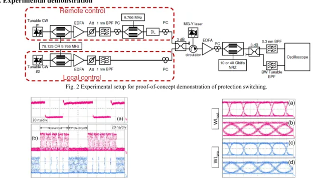
3. Experimental demonstration
Fig. 2 Experimental setup for proof-of-concept demonstration of protection switching.
Fig. 3 All-optical protection switching demonstration: (a) Gating window for emulating the link failure. Waveform on (b) WLopt in
normal mode and (c) WLpro in protection mode.
Fig. 4 Eye diagrams of the data at the transmitter output under normal operation on WLopt at (a) 10 Gbit/s and (b) 40 Gbit/s, as well as
under protection operation on WLpro at (c) 10 Gbit/s and (d) 40 Gbit/s. Fig. 2 shows the experimental setup used for the proof-of-concept demonstration of the proposed scheme. The AOWFF used in the experiment is a single modulated grating Y-branch (MG-Y) laser structure [4], in which flip-flop operation over a large wavelength tunable range has been recently demonstrated, with switching time less than 200 ps and 0.16-0.34 pJ control pulse energy [5]. Two tunable CW lasers were externally modulated using two Mach-Zehnder modulators (MZMs) in order to generate the 50 ps long control pulses with, at first, a low repetition rate of 78.125 MHz. The control pulses were amplified in erbium-doped fiber amplifiers (EDFAs), filtered in optical band-pass filters (BPFs) and their relative delay was adjusted using an optical delay line (DL) before they were injected into the MG-Y laser via a circulator. The state of polarization of the control signals was beforehand adjusted using polarization controllers (PCs). The MG-Y laser operated at a bistable window with two states on 1554.37 nm
20 ns/div 20 ns/div
Normal Opt Protect Opt
(a) (b) WL opt WL pr o (a) (b) (c) (d)
or 1554.66 nm. Its output was then modulated with 10 Gbit/s or 40 Gbit/s non return-to-zero (NRZ) data with a 231−1 pseudo-random binary sequence (PRBS). Two BPFs were used to emulate an AWG and route the signal to a different port depending on its wavelength. The signals at the operation wavelength and at the protection wavelength were then monitored on an optical sampling oscilloscope. To emulate the link failure, the remote control pulses were periodically suppressed using another MZM driven at 9.766 MHz, resulting in 3 out of 8 CtrlR pulses being suppressed. The dynamic extinction ratio of the modulator was about 10 dB and the gating window generated by the MZM can be seen in Fig. 3(a).
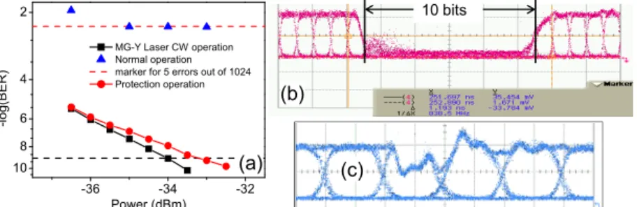
Fig. 5 Link performance with 10 Gbit/s NRZ data: (a) BER measurement. (b) Time interval between two adjacent frames on WLopt in normal operation and (c) Bits on WLpro affected by the local control pulses in protection operation.
In order to illustrate the scheme, the waveforms on both wavelengths in both normal operation and protection regime are shown in Fig. 3(b)-(c). Under normal operation, as indicated in the figure, 5 frames of data traffic on
WLopt can be seen. In Fig. 3, a short frame length of ~100 bits at 10 Gbit/s was chosen in the experiment to ease the visualization of the process on the oscilloscope traces, but the scheme is obviously highly scalable towards lower repetition rates of the control signals, allowing much longer data frames to be transmitted.
The next 3 CtrlR pulses were suppressed, emulating a cut in the working path. As shown in Fig. 3(c), the data was immediately switched to WLpro while no more data was sent on WLopt, as can be seen in Fig. 3(b), apart from some residual out-of-band crosstalk leaking through the 0.3 nm OBPF used for signal separation in our proof-of-concept implementation. Fig. 4 shows the eye diagrams of both WLopt in normal operation and WLpro in protection operation with 10 Gbit/s and 40 Gbit/s data modulation. The eyes are both widely open, indicating good signal quality. BER measurements were also performed with 10 Gbit/s NRZ data modulation, as shown in Fig. 5(a). When modulating the MG-Y laser output without any control pulses, the sensitivity is about -34 dBm (at BER=10−9). Unfortunately, due to the lack of a proper burst gating control, BER measurements for both normal and protection operations could only be performed in continuous gating mode. For error counting, the repetition rate of the control signals was set to 9.766 MHz, allowing 1024 bits of 10 Gbit/s signal in every period. As 10 bits were switched off from WLopt between two adjacent frames, as shown in Fig. 5(b), and assuming an equal distribution of marks and spaces when averaging over many frames, 5 bits on average would be erroneously detected even if no error occurs during normal operation, leading to a minimum achievable BER of 4.9×10⁻³. The measured BER of WLopt with sufficient receiver power was exactly lying on this level, indicating no performance degradation for the bits transmitted over the frame. On WLpro, some bits were affected by CtrlL, as shown in Fig. 5(c), since it disturbed the carrier density of the MG-Y laser, causing a moderate power penalty compared to CW operation, as shown in Fig. 5(a).
6. Conclusion
A novel concept of all-optical protection switching was proposed. Link failure detection and protection trigger were both implemented on the optical layer. The concept was experimentally demonstrated using a wavelength tunable AOWFF based on a single MG-Y laser structure. The achieved protection switching time was less than 200 ps. The good quality of the signal following the establishment of the protection path was evaluated at 10 and 40 Gbit/s. The method provides a fast establishment of the protection path, resulting in a minimum loss of data for critical applications, while the failure can still be detected by conventional slower means (e.g. by monitoring the power at the output ports of the wavelength router) resulting in the network management being informed by the protocol and appropriate measures being taken.
References
[1] R. Ramaswami, et. al., Optical Networks A Practical Perspective (Morgan Kaufmann, 2010), chap. 9, pp. 511–572. [2] “ITU-T Recommendation G.841,” (1998). Available from http://www.itu.int/rec/T-REC-G.841-199810-I/en. [3] A. Chowdhury, et. al., OFC’11, paper OThK6 (2011).
[4] J-O. Wesstr öm,, et. al., OFC’04, paper TuE2 (2004). [5] Y. An, et al., PS’12, paper Fr-S18-O21 (2012).
10 bits -36 -34 -32 10 8 6 4 2 -l og( BER) Power (dBm)
MG-Y Laser CW operation Normal operation marker for 5 errors out of 1024 Protection operation
(a) (b)