Cyclic behaviour of steel ring filled with compressive plastic or
concrete, installed in the concentric bracing system
Mostafa Kazemia, Mohammad Ali Kafib*, Mohammad Hajforoushc, and Ali Kheyroddind
a
MSc Graduate Student, Department of Civil Engineering, University of Guilan, Rasht, Iran b
Associate Professor, Department of Civil Engineering, Semnan University, Semnan, Iran c
PhD Student Department of Civil Engineering, Semnan University, Semnan, Iran d
Professor, Department of Civil Engineering, Semnan University, Semnan, Iran *(Corresponding author: E-mail: mkafi@semnan.ac.ir)
Abstract
The present study intended to evaluate the dynamic behaviour of steel ring filled with compressive plastic (S.R.P.) or high-performance fibre-reinforced cementitious composites (S.R.C.) situated at the intersection of the braces. High-performance fibre-reinforced cementitious composites and plastic materials, associated with steel ring connection, seem to be helpful to dissipate the energy through braces better. Therefore, in this paper, the behaviour of S.R.C. and S.R.P. connections was analyzed under cyclic loading. Results showed a steady and relatively wide hysteresis curve for both connections, where the tensile ductility factors of S.R.P. and S.R.C. connections were found to be equal to 2.77 and 13.66, respectively. However, in general, the plastic ring, being operated efficiently to delay appearing the inelastic zone in the S.R.P. connection, was proved to outperform the HPFRCC material in the S.R.C. connection. In addition, numerical results revealed that maximum tensile and compressive loads of S.R.P. connection made with ST52 steel ring were found to be 14% and 10.7%, respectively, higher than those of S.R.P. connection made with ST37 steel ring.
1. Introduction
Among structural systems, the concentric bracing system has been known for its
advantages, including high stiffness, reconstruction, and easy repair after occurring earthquake. However, the poor ductility of bracing systems, causing to reduce the redundancy
factor, after applying cyclic load is one of the major weaknesses of steel concentric brace
connections. This manner leads to a decrease in the load-bearing capacity of structure (Bazzaz et al. 2015; Murthy and Narayan 2005).
By considering the fact that lateral load-resisting systems should have two characteristics
of high stiffness and ductility associated with their resistance to maintain their suitable
performance in structures, over the past few years, severe damages to non-ductile connections have drawn the attention of engineers to analyze the behaviour of new buildings based on the seismic codes and construct earthquake-resistant braces (Oh et al. 2009; Mazloom et al.
2019). Among different types of connections, steel ring, as an energy-dissipater, can
efficiently dissipate energy among the structural members of the bracing system. In addition,
high-performance fibre-reinforced cementitious composites (HPFRCC) and plastic materials can be employed for transforming and dissipating the energy (Saberian et al. 2018; Naaman
and Reinhardt 2003; Saberian et al. 2019). Therefore, it can be inferred that the combination
of HPFRCC and plastic materials with steel ring seems to affect the cyclic behaviour of steel connection and the energy dissipation through braces. Following this, the present study was
plastic (S.R.P.) or HPFRCC (S.R.C.) as energy-dissipating fuses with bending, situated at the
intersection of the braces. The S.R.P. connection has also been analyzed by means of finite
element method employing ABAQUS software, thereby being detected the stress distribution in this connection numerically.
2. Literature review
Some studies have been conducted by researchers to evaluate the performance of some devices and connections such as friction device and slotted bolted connection in bracing
systems (Mualla and Belev 2002; Pall and Marsh 1982; Butterworth 2000; Grigorian et al.
1993; Thomopoulos and Koltsakis 2003) and even some researchers such as Thomopoulos
and Koltsakis (2003) and Tehranizadeh (2001) have investigated the effects of connections as suitable energy dissipaters to improve the behaviour of bracing systems against lateral and seismic loading. Of all different types of connections, steel ring seems to be capable to
efficiently dissipate the energy through braces as revealed by Andalib et al. (2014). Due to
lack of access to seamless Mannesmann pipes in every diameter and thickness, they used of
steel ring connection, made of two half-rings formed by the rolling of steel plates, which could be easily installed and replaced at the point of connection between the brace and the
corner connection plate. They demonstrated the half-ring connections were capable of
enhancing ductility and absorbing energy as a dissipater member where the steel ring indicated a steady and relatively wide hysteresis curve; meanwhile, their experimental
members of the bracing system owing to remaining diagonal braces in their elastic zone.
Abbasnia et al. (2008) experimentally and analytically evaluated the ductility of steel ring
where this connection depicted suitable performance in the diagonal bracing system. They also concluded that the maximum tensile and compressive loads were 87.7 and 73.7 KN,
respectively. In addition, Bazzaz et al. (2012) reported that the installation of steel ring in the
bracing system was very easy and this connection led to a decrease in construction costs. The use of this ductile element with high displacement contributed to a decrease in displacement
of a frame and subsequently led to the higher dissipation of energy in the bracing system. In
another study by Bazzaz et al. (2012), the performance of steel ring at the end of off-centre
bracing system was assessed, where they found that this connection was the first defensive line and buckling fuse in the off-centre bracing system.
The energy dissipation performance of HPFRCC and plastic materials in structural
members has been assessed by researchers. Concerning this, Saghafi et al. (2019) showed that
the HPFRCC provided suitable energy-dissipation and load-bearing capacities under dynamic
loading. Parra-Montesinos et al. (2005) assessed the cyclic behaviour of HPFRCC including polypropylene fibre in the beam-column connection, where HPFRCC showed a large
compression strain capacity and an outstanding damage tolerance in flexural members.
Similar results were also reported by Parra-Montesinos (2005). He also concluded that HPFRCC can be considered as a highly qualified material to utilize in plastic hinge regions of
be employed in reinforced concrete column and steel beam connections by Parra-Montesinos
(2000), where it showed a good inelastic cyclic response and suitable stiffness retention
capacity. Regarding the plastic material, Kortis et al. (2015) investigated the behaviour of plastic material in double-shear-plane timber-steel structural connection. They showed that
plastic material prevented the local concentration of stress in this connection. Furthermore,
Gajan and Saravanathiiban (2011) found that the combination of plastic material with steel material led to dissipating energy in structural devices and foundation soil during seismic
loading.
3. Model properties and materials characteristics
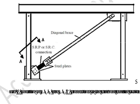
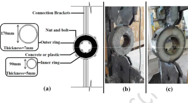
Fig. 1 shows the location of S.R.P. and S.R.C. connections in the diagonal bracing system. In addition, the geometric details of these connections, used in the present study, are shown in Fig. 2a. Due to lack of access to seamless Mannesmann pipes in every thickness, two
seamless Mannesmann pipes with two different diameters were used as inner and outer steel
rings where the outer steel ring was welded to attaching plates. Then, these two steel rings
were filled with concrete or compressive plastic ring which they were connected using nut and bolt (Figs. 2b and 2c). The type of steel rings in experimental program was ST37 and
grade 8.8 nuts and bolts, based on DIN 931 standard (1986), were used for connecting
different rings. As depicted in Fig. 2a, the external diameters of inner and outer steel rings were equal to 90 mm and 170 mm, respectively. Meanwhile, the thicknesses of inner and
means of a hydraulic jack to S.R.P. and S.R.C. connections based on ATC_40 code (1996). In
addition, two 10-cm displacement gauges were also employed for measuring the vertical
displacement of these connections. The mechanical properties of steel and plastic rings are presented in Table 1 where and are yield stress and strain, respectively. Also, is
ultimate stress and is corresponding strain. In addition, the bilinear stress-strain curve in
Fig. 3 shows the behaviour of plastic ring.
On the other hand, since the concrete had lower tensile strength, some materials with a
strain-hardening response under tensile loading have been proposed by researchers (Sakthivel
et al. 2019; Shanthi and Jagannatha Reddy 2019; Saradar et al. 2018; Jahandari 2015; Vali et al. 2019). One of these materials is the HPFRCC material, which was used in the S.R.C.
connection to achieve sufficient ductility under cyclic loading. The polypropylene fibre with
the volume fraction of 1% was added in the concrete mixture as suggested by Hemmati et al. (2016). The density and tensile strength of polypropylene fibre were 0.91 g/cm and 400 MPa, respectively. The length and diameter of polypropylene fibre were equal to 12 mm and 18 µm, respectively. Type II Portland cement with the density of 3.2 g/cm and surface area of 2900 cm /g was used. The fine aggregate with the specific density of 2.72 g/cm and water absorption of 5.1% was collected from natural river sand. A superplasticizer of
polycarboxylic ether-type, suited for improving the workability of concrete, was provided
(AzariJafari et al. 2019; Khotbehsara et al. 2018; Sadrmomtazi et al. 2018; AzariJafari et al. 2015; Gholhaki et al. 2018).
For mix preparation, the sand, and coarse natural aggregate were first mixed for 30 s at normal
speed. Then, half of the tap water was added into the mixer and mixing went on for 1 min.
Thereafter, cement was added and mixed for one more minute (Table 2). Then, the fibres, along with the remaining water and superplasticizer, were intermittently and slowly introduced in the mixer, and mixing went on for 3 min. This procedure prevented clustering of the polypropylene
fibres and thoroughly distributed them in the concrete mass as advised by Hemmati et al. [47].
Fig. 2. Geometric details of S.R.C. and S.R.P. connections (a); Configuration of S.R.P. connection
(b); Configuration of S.R.C. connection (c)
Table 1. Mechanical properties of steel rings and plastic material
Member Type (MPa) (MPa) Young's modulus (GPa) Poisson ratio Steel ring ST37 240 370 0.1 0.3 210 0.3 ST52 360 520 0.1 0.3 280 0.3 Plastic ring - 150 240 0.1 0.3 0.15 0.2
Fig. 3. The bilinear stress-strain curve for plastic ring
0 5 10 15 20 25 30 0 0.05 0.1 0.15 0.2 0.25 0.3 0.35 St re ss ( N /m m 2) Strain
Table 2. Mix proportion of HPFRCC Polypropylene fibre (volume fraction) Superplasticizer Coarse aggregate Fine aggregate Cement Water/Cement Material 1% 0.01 - 1 1 0.54 HPFRCC
4. Experimental results and discussion
4.1. S.R.P. connection
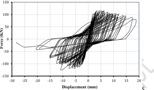
According to the experimental results, the maximum tensile and compressive loads were 124.4 and 126.95 KN and the corresponding displacements were 10.8 and 10.7, respectively,
as shown in Fig. 4. In a similar study on the ductility of steel ring, Abbasnia et al. (2008)
concluded that the maximum tensile and compressive loads were 87.7 and 73.7 KN, respectively. This matter shows that the maximum tensile and compressive loads of S.R.P.
connection are 41.9% and 72.3% higher than those of steel ring, respectively. Fig. 5 shows the hysteresis loop push force-vertical displacement plot. Two linearizations have been
performed by the FEMA 356 proposed method (2000). The maximum vertical displacement (∆ ) and corresponding vertical displacement of the system at the end of the tensile elastic limit (∆ ) were 16.01 mm and 5.78 mm, respectively. The ductility factor ( ) of this system for tensile loading is defined using Eq. (1). It can be inferred that the plastic ring in conjunction with steel rings efficiently scattered the energy under tensile loading in both
elastic and inelastic zones. The reason is that the plastic ring delayed appearing the inelastic zone in the S.R.P. connection up to the vertical displacement of 5.78 mm (∆ ), thereby being prevented the generation of inelastic zone abruptly. After the evolution of inelastic zone, the
plastic ring was well operated in conjunction with steel rings to enhance the maximum vertical displacement (∆ ) of S.R.P. connection up to 16.01 mm.
=∆
∆ =
.
. = 2.77 (1)
Eq. (2) presents the elastic stiffness (K ) at tension. K =
∆ =
.
. = 17.21 (KN/mm) (2)
Where P is the yielding force (KN).
The maximum vertical displacement (∆ ) and corresponding vertical displacement of the system at the end of the compressive elastic limit (∆ ) were 11.5 mm and 5.32 mm,
respectively. The ductility factor ( ) of this system for compressive loading is presented in
Eq. (3). Similar to the tensile loading, there was a good operation between plastic and steel rings in both elastic and inelastic zones under compressive loading, where the value of ∆ under compressive loading was found to be very close to that under tensile loading. In addition, the maximum vertical displacement (∆ ) under compressive loading was more than 2 times of compressive elastic limit (∆ ), similar to what was revealed under tensile loading.
=∆
∆ =
.
. = 2.16 (3)
Eq. (4) presents the elastic stiffness (K ) at compression. Based on the results, the values of P and K under compressive loading were found to be close to those under tensile
loading. Therefore, it can be concluded that there was a balance for dissipating energy under both tensile and compressive loading for the S.R.P. connection.
K =
∆ =
.
. = 19.1 (KN/mm) (4)
To compare the results of this study with those of single steel ring connection given by
Andalib et al. (2014), it can be stated that the ductility factor ( ) of the single steel ring was
found to be 1.6 times more than that of the S.R.P. connection at tension. This difference was
obtained 2.6 times at compression. Therefore, it seems that single steel ring connection was
more ductile than the S.R.P. connection at both tension and compression.
Fig. 4. Comparative hysteresis curves for S.R.P. connection with ST37 steel ring
Fig. 5. Hysteresis loop push force-displacement plot for S.R.P. connection -150 -100 -50 0 50 100 150 -20 -15 -10 -5 0 5 10 15 20 Performance S.R.P. Displacement (mm) F o rc e (K N ) ∆ = . ∆ = . ∆ = . ∆ = . = . Pu= 0.8 = . = . Pu= 0.8 = .
Figs. 6 and 7 depict the energy-loading cycle plot and cumulative energy-loading cycle plot for S.R.P. connection, respectively. According to Fig. 6, the maximum energy in elastic cycles (E ) was equal to 260.2 j and this value in inelastic cycles (E ) was 5554.5 j. The ratio of maximum energy in inelastic to elastic cycles was equal to 21.3 which it can be inferred that energy absorption in inelastic cycles was more than that in elastic cycles; therefore, this
connection had a high ductility. As shown in Fig. 7, the total dissipated energy at the end of
the loading cycle was 33492.1 J. This value showed that S.R.P. connection can be considered as a suitable energy-dissipating fuse under cyclic loading in the concentric bracing system.
Fig. 6. Energy-loading cycle plot
Fig. 7. Cumulative energy-loading cycle plot
0 1000 2000 3000 4000 5000 6000 0 1 2 3 4 5 6 7 8 9 10 11 12 13 14 15 16 17 18 19 20 21 S.R.C. S.R.P. E n e rg y ( J o u le ) Cycle 0 5000 10000 15000 20000 25000 30000 35000 40000 45000 0 1 2 3 4 5 6 7 8 9 10 11 12 13 14 15 16 17 18 19 20 21 S.R.C. S.R.P. C u m u la ti v e E n e r g y ( J o u le ) Cycle
4.2. S.R.C. connection
As indicated in Fig. 8, the maximum tensile and compressive loads were found to be
115.76 and 126.1 KN and the corresponding displacements were 6.4 and 10.7 mm, respectively, based on the experimental outputs. The maximum tensile and compressive loads
of S.R.C. connection were 32% and 71.1% more than those of steel ring, used by Abbasnia et
al. (2008). The hysteresis loop push force-vertical displacement plot for the S.R.C. connection presents in Fig. 8. The maximum vertical displacement (∆ ) and corresponding vertical displacement of the system at the end of the tensile elastic limit (∆ ) were 17.07 mm and 1.25 mm, respectively. The ductility factor ( ) of this system for tensile loading is
defined using Eq. (5). The results showed that the HPFRCC material was unable to efficiently
operate in conjunction with steel rings to increase the displacement of S.R.C. connection in elastic zone and after a small value of vertical displacement (1.25mm), the inelastic zone
abruptly appeared (Fig. 9). However, after the evolution of inelastic zone, there was a great
cooperation between HPFRCC material and steel rings to achieve the maximum vertical
displacement of 17.07 mm under tensile loading. This manner can be due to the fact that concrete was a brittle material and it had lower tensile strength (Hajforoush et al. 2019; Jahandari et al. 2019; Madandoust et al. 2017; Jahandari et al. 2017(a)), but at higher
displacements when some microscopic cracks were generated in concrete, the inclusion of
subsequently increased the value of ∆ . That’s why the ductility factor ( ) of the S.R.C. connection was obtained very high at tension.
=∆
∆ =
.
. = 13.66 (5)
Eq. (6) presents the elastic stiffness (K ) at tension. K =
∆ =
.
. = 74.08 (KN/mm) (6)
Where P is the yielding force (KN).
The maximum vertical displacement (∆ ) and corresponding vertical displacement of the system at the end of the tensile elastic limit (∆ ) were 10.99 mm and 1.83 mm, respectively. The ductility factor ( ) of this system for compressive loading is presented in Eq. (7). Similar to the tension, the value of ∆ at compression was not very high. But, the value of ∆ was attained up to the 10.99 mm, which was 55.3% less than that at tension. This manner
showed that there was a limited agreement between tensile and compressive loading regarding the performance of HPFRCC material and steel rings, particularly in the inelastic
zone, even though the inclusion of polypropylene fibre in HPFRCC generated much resistance to compressive loading to achieve high value of ∆ (10.99 mm).
=∆
∆ =
.
. = 6 (7)
Eq. (8) presents the elastic stiffness (K ) at compression. According to the outputs, the values of P and K at compression were 10% and 34.4% less than those at tension, and, as it was previously mentioned, the value of ∆ at compression was found to be 55.3% less than
that at tension. Therefore, it can be concluded that although the performance of HPFRCC
material and steel rings each other was suitable in the inelastic zone, there was not a
sufficient balance between tensile and compressive loading to dissipate the energy in S.R.C. connection.
K =
∆ =
.
. = 55.13 (KN/mm) (8)
The results of S.R.C. connection in this study were compared with those of single steel
ring connection given by Andalib et al. (2014). It can be stated that the ductility factor ( ) of
the S.R.C. connection was found to be 3 times more than those of the single steel ring connection at tension, while there was no significant difference between the ductility factor of
these two connections at compression. As mentioned previously, the presence of HPFRCC material in S.R.C. connection caused to obtain low value of ∆ at tension (1.25mm) and the inelastic zone abruptly appeared in this connection, while by increasing the displacement and
generating micro-cracks in HPFRCC, polypropylene fibres could bridge the cracks as observed by other researchers (Sadrmomtazi et al. 2018), leading to an increase in the
maximum vertical displacement (∆ ) up to 17.07 mm at tension. This contributed to
obtaining high value of ductility factor ( ) for the S.R.C. connection. That’s why this factor
for the S.R.C. connection was obtained about 3 times more than that for the single steel ring
Fig. 8. Comparative hysteresis curves for S.R.C. connection with ST37 steel ring
Fig. 9. Hysteresis loop push force-displacement plot for S.R.C. connection
The energy-loading cycle plot and cumulative energy-loading cycle plot are presented in Figs. 6 and 7, respectively. As shown in Fig. 6, the maximum energy in elastic cycles (E ) was found to be 131.1 j and this value in inelastic cycles (E ) was 5000 j. The ratio of maximum energy in inelastic to elastic cycles was 38.16 which revealed that energy
-150 -100 -50 0 50 100 150 -25 -20 -15 -10 -5 0 5 10 15 20 25 Performance S.R.C. Displacement (mm) F or ce ( K N ) ∆ = . ∆ = . ∆ = . ∆ = . = . = . Pu= 0.8 = . Pu= 0.8 = .
absorption in inelastic cycles was far more than that in elastic cycles; therefore, this
connection had high ductility. The total dissipated energy at the end of the loading cycle is
37944 j, as indicated in Fig. 7. This value shows that S.R.C. connection can be considered as a suitable energy-dissipating fuse under cyclic loading in the concentric bracing system.
4.3. A comparison between the results of S.R.P. and S.R.C. connections
According to the experimental observations, there was no significant difference between
the maximum compressive loads of S.R.P. and S.R.C. connections, even though the
maximum tensile load of S.R.P connection was found to be 7.5% more than that of S.R.C.
connection. Both maximum tensile and compressive displacements of S.R.P. connection were
roughly 35% higher than those of S.R.C. connection. The plastic ring, being operated efficiently to delay appearing the inelastic zone in the S.R.P. connection, was proved to outperform the HPFRCC material in the S.R.C. connection. The reason is that the inelastic
zone in S.R.C. connection abruptly appeared after a small value of vertical displacement
(1.25mm). The results showed that both connections suitably dissipated the energy in
inelastic zone during cyclic loading. It can be due to the fact that the polypropylene fibre in HPFRCC and plastic ring generated much resistance to cyclic loading. However, unlike the
S.R.C. connection, the values of ductility factor ( ) and elastic stiffness (K ) for the S.R.P.
connection at tension were close to the same values at compression, particularly in the
The cumulative energy of S.R.P. and S.R.C. connections in different cycles can be
compared to each other as shown in Fig. 7. The results showed that the curve slope of
cumulative energy for both connections were nearly the same by increasing the number of cycles. In addition, the maximum cumulative energy of S.R.C. connection was found to be
28.4% higher than that of S.R.P. connection. To better understand and compare the cyclic
performance of S.R.P. and S.R.C. connections, it is required to analyze the energy absorption of these connections in each cycle as indicated in Fig. 6. According to Fig. 6, there was an
increase in energy absorption of S.R.P. connection in inelastic cycles (up to the 5th cycle).
Later on, an increase in the energy absorption became steeper in inelastic cycles (up to the
11th cycle). Finally, by decreasing the energy absorption, the S.R.P. connection was failed in the 16th cycle. Concerning the S.R.C. connection, the inelastic zone abruptly appeared in the S.R.C. connection after the 1st cycle and there was a fluctuation in terms of energy absorption
between the 8th and 12th cycles. This fluctuation can be due to the complex behaviour of
HPFRCC in higher displacements, even though the presence of polypropylene fibre in
HPFRCC was able to increase the maximum energy of the S.R.C. connection in inelastic cycles (E ) up to 5000 j. In general, by considering the fact that the S.R.P. connection had a better performance compared to the S.R.C. connection, the dynamic behaviour of the S.R.P. connection was numerically analyzed in the following to provide more descriptions in details
about stress distribution under cyclic loading.
5.1.Description of the numerical model
According to Table 1, the mechanical properties were defined and three dimensional (3D)
hexahedral element with 8 nodes and reduced integration (C3D8R) were employed for
numerical modeling as provided in ABAQUS software and used by other researchers (Hibbitt and Karlsson 2011; Madandoust et al. 2018; Madandoust and Kazemi 2017). The type of steel
rings in numerical studies was first considered ST37 and for further investigation, the properties of ST52 steel were defined to the software. In addition, the bilinear
stress-strain curve for plastic ring, assigned to the software, is shown in Fig. 3. Based on
experimental observations, plastic and steel rings remained their contact surfaces at the right and left sides of S.R.P. connection between nut and bolt during tensile and compressive
loading, while contact surfaces in the upper and lower parts of connection didn't have any
interaction during tensile loading. Following this, the ABAQUS tie constraint function was used for contact surface between plastic and steel rings at the right and left sides in numerical
modeling as indicated in Fig. 4 to maintain interaction during tensile and compressive
loading, while the surface to surface contact was used for upper and lower parts of S.R.P. connection between plastic and steel rings to maintain interaction in these parts only during
compressive loading. Similar to the method of loading in the experimental program, cyclic loading was numerically applied to S.R.P. connection for performing the nonlinear analysis
Fig. 10. Numerical configuration of S.R.P. connection
5.2.Analysis of numerical modeling
To verify the numerical model, the hysteresis plot of the analytical model for ST37 was compared with that of the experimental study as shown in Fig. 4 where the maximum tensile
loads for experimental and numerical models were 124.4 and 121.1 KN and the corresponding displacements were 10.8 and 12.3 mm, respectively. In addition, maximum
compressive loads for experimental and numerical models were 126.95 and 121.9 KN and the
corresponding displacements were 10.67 and 11.7 mm, respectively. These results showed that the difference in maximum load between experimental and numerical results in each case
of tension and compression was about 2.7% and 4.1%, respectively. Furthermore, the general
shape of the hysteresis curve for numerical simulation, subjected to cyclic loading, was similar to that for experimental outputs. These results demonstrated that there was a good
The numerical model provided a better understanding of the stress distribution, failure
mechanism and ultimate capacity of S.R.P. connection, thereby being predicted the crack
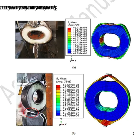
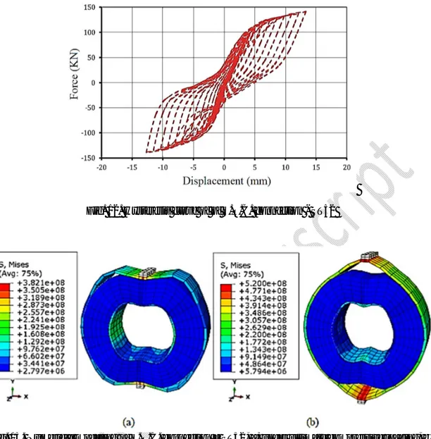
propagation path by the stress contours. The experimental configuration of S.R.P. connection and the stress distribution of numerical model are shown in Fig. 11 under ultimate tensile and
compressive loading. As indicated in Fig. 11a, the maximum stress in S.R.P. connection
under compressive loading occurred in the outer steel ring, close to where it was connected to attaching plate, and also the right and left sides of the inner steel ring where this stress was
found to be equal to 171.3 MPa. The appearance of maximum stress in both inner and outer
steel rings showed that the plastic ring efficiently dissipated the energy in the S.R.P.
connection under compressive loading. By considering the fact that the yield stress of ST37 steel ring was equal to 240 MPa, there was no evidence for appearing the inelastic zone in the inner and outer steel rings under compressive loading.
According to Fig. 11b, experimental results showed that the S.R.P. connection was failed
under ultimate tensile loading, close to where it was welded to attaching plate. This fracture
zone was also observed for the single steel ring in the study by Andalib et al. (2014). As per the numerical modeling (Fig. 11b), the maximum stress was found to be approximately equal
to 360 MPa, which appeared in the outer steel ring under ultimate tensile loading. Since this
value was close to the ultimate stress of ST37 steel ring, it can be inferred that the high-stress intensity occurred in the outer steel ring, close to where it was connected to attaching plate,
steel ring was equal to 240 MPa, there was rare evidence for forming the inelastic zone on the inner steel ring under tensile loading.
It is noteworthy that all stresses, generated in the plastic ring under both compressive and
tensile loading, were found to be less than 150 MPa (the yield stress of plastic ring) as shown
in Fig. 11. Therefore, it can be concluded that only evidence of elastic zone was formed on the plastic ring and there was no evidence for appearing the inelastic zone in this ring. This manner showed that there was no fatigue for the plastic ring during the cyclic loading, while
this component of the S.R.P. connection efficiently contributed to dissipating the energy
between inner and outer steel rings.
Fig. 11. Experimental configuration and numerical modeling of S.R.C. connection – ST37, a) under
To evaluate various types of steel rings, mechanical properties of St52 were assigned to
inner and outer rings. The hysteresis plot of analytical model for ST52 is shown in Fig. 12
where the maximum tensile load and corresponding displacement were equal to 141.8 KN and 13.3 mm, respectively. Furthermore, the maximum compressive load and corresponding
displacement were equal to 140.5 KN and 12.8 mm, respectively. These numerical results
indicated that the use of ST52 steel ring in S.R.P. connection increased maximum tensile and compressive loads up to 14% and 10.7%, respectively, compared to the use of ST37 steel
ring.
The stress distribution for S.R.P. connection with ST52 steel ring is shown in Fig. 13.
Similar to S.R.P. connection with ST37 steel ring, S.R.P. connection with ST52 steel ring was failed under ultimate tensile loading, close to where it was welded to attaching plate and high-stress intensities occurred in the vicinity of attaching plate. As shown in Fig. 13, all
stresses, generated in the plastic ring under both compressive and tensile loading, were found
to be less than 150 MPa (the yield stress of plastic ring) and there was no evidence for
forming inelastic zone on the plastic ring. These results showed that although fatigue did not occur for the plastic ring during the cyclic loading, it could efficiently distribute the cyclic
Fig. 12. Hysteresis curve of of S.R.C. connection - ST52
Fig. 13. Numerical modeling of S.R.C. connection – ST52, a) under ultimate compressive loading, b)
under ultimate tensile loading 6-Conclusion
In this paper, the performance of S.R.P. and S.R.C. connections was evaluated experimentally under cyclic loading and also the S.R.P. connection with ST37 or ST52 steel
rings has been numerically analyzed by means of finite element method employing ABAQUS software. The following conclusions can be drawn from this investigation:
The results revealed that energy absorption of S.R.P. and S.R.C. connections in
energy in inelastic to elastic cycles for S.R.P. and S.R.C. connections were found to
be equal to 21.3 and 38.16, respectively. This matter demonstrated that these
connections can be classified as high-ductile connections;
The total dissipated energies at the end of the loading cycle were 33492.1 j and 3794 j
for the S.R.P. and S.R.C. connections, respectively, which show that they can be considered as a suitable energy-dissipating fuse under cyclic loading in the concentric bracing system;
Generally, the plastic ring in the S.R.P. connection was proved to outperform the
HPFRCC material in the S.R.C. connection, where, unlike the S.R.C. connection, the
plastic ring in the S.R.P. connection prevented the generation of inelastic zone
abruptly, even though the presence of polypropylene fibre in HPFRCC was able to increase the maximum energy of the S.R.C. connection in inelastic cycles (E ) up to 5000 j;
The results were indicative of the fact that the numerical modeling of S.R.P.
connection efficiently predicted the fracture zone similar to experimental observations
where maximum compressive and tensile loads, obtained in the experimental program, were 2.7% and 4%, higher than those in the numerical model, respectively;
Both experimental results and contours of stress distribution revealed that S.R.P.
to attaching plate, while there was no evidence for appearing the inelastic zone in the
plastic ring. So, the fatigue did not occur in this ring during the cyclic loading;
The numerical results indicated that the use of ST52 steel ring in S.R.P. connection
enhanced maximum tensile and compressive loads up to 14% and 10.7%,
respectively, compared to the S.R.P. connection with the ST37 steel ring.
Conflict of interest
No potential conflict of interest was reported by the authors.
References
Abbasnia, R., Vetr, M.G.H., Ahmadi, R., & Kafi, M.A. (2008) Experimental and analytical investigation on the steel ring ductility. Sharif Journal of Science and Technology, 52, 41–48.
Andalib, Z., Kafi, M.A., Kheyroddin, A., & Bazzaz, M. (2014) Experimental investigation of the ductility and performance of steel rings constructed from plates. Journal of Constructional Steel Research, 103, 77–88. ATC-40 (1996) Guidelines for cyclic seismic testing of components of steel structures. Redwood City, USA. AzariJafari, H., Amiri, M.J.T., Ashrafian, A., Rasekh, H., Barforooshi, M.J., & Berenjian J. (2019) Ternary
blended cement: an eco-friendly alternative to improve resistivity of high-performance self-consolidating concrete against elevated temperature. Journal of Cleaner Production, 223, 575-586.
AzariJafari, H., Shekarchi, M., Berenjian, J., & Ahmadi, B. (2015) Enhancing workability retention of concrete containing natural zeolite by superplasticizers’ combination. Special Publication, 302, 416–424.
Bazzaz, M., Andalib, Z., Kafi, M.A., & Khyroddin, A. (2015) Evaluating the Performance of OBS-C-O in Steel Frames under Monotonic Load. Earthquakes and Structures, 8(3), 697-710.
Bazzaz, M., Kheyroddin, A., Kafi, M.A., & Andalib, Z. (2012) Evaluation of the seismic performance of off-centre bracing system with ductile element in steel frames. Steel and Composite Structures, 12(5), 445-464.
Butterworth, J. (2000) Ductile concentrically braced frames using slotted bolted joints. Structural Engineering
Society New Zealand, 13, 39-48.
DIN 931-1. (1986) M1.6 to M39 Hexagon Cap Screws Partially Threaded. Deutsches Institut für Normung, Germany.
FEMA 356. (2000) Prestandard and commentary for the seismic rehabilitation of buildings.
Gajan, S., & Saravanathiiban, D.S. (2011) Modeling of energy dissipation in structural devices and foundation soil during seismic loading. Soil Dynamics and Earthquake Engineering, 31(3), 1106–1122.
Gholhaki, M., Kheyroddin, A., Hajforoush, M., & Kazemi, M. (2018). An investigation on the fresh and hardened properties of self-compacting concrete incorporating magnetic water with various pozzolanic materials.
Construction and Building Materials, 158, 173–180.
Grigorian, C.E., Yang, T.S., & Popov, E.P. (1993) Slotted bolted connection energy dissipaters. Earthquake
Spectra, 9(3), 491-504.
Hajforoush, M., Madandoust, R., & Kazemi, M. (2019) Effects of simultaneous utilization of natural zeolite and magnetic water on engineering properties of self‑compacting concrete, Asian Journal of Civil Engineering,
20(2), 289-300.
Hemmati, A., Kheyroddin, A., Sharbatdar, M., Park, Y., & Abolmaali, A. (2016) Ductile behavior of high-performance fiber reinforced cementitious composite (HPFRCC) frames. Construction and Building
Materials, 115, 681-689.
Hibbitt, D., Karlsson, B., & Sorensen, P. (2011) ABAQUS standard user’s manual (Version 6.11-3), Dassault Systèmes Simulia Corp. Providence, Rhode Island, USA.
Jahandari, S. (2015) Laboratory study of moisture and capillarity impact on lime concrete resistance due to the increase of ground water level. M.Sc. thesis, Faculty of Civil and Surveying Engineering, Department of Geotechnical Engineering, Graduate University of Advanced Technology, Kerman, Iran.
Jahandari, S., Saberian, M., Tao, Z., Faridfazel Mojtahedi, S., Li, J., Ghasemi, M., Rezvani, S.S., & Li, W. (2019) Effects of saturation degrees, freezing thawing, and curing on geotechnical properties of lime and lime-cement concretes. Cold Regions Science and Technology, 160, 242–251.
Jahandari, S., Li, J., Saberian, M., & Shahsavarigoughari, M. (2017(a)) Experimental study of the effects of geogrids on elasticity modulus, brittleness, strength, and stress-strain behavior of lime stabilized kaolinitic clay. GeoResJ, 13, 49-58.
Khotbehsara, M.M., Miyandehi, B.M., Naseri, F., Ozbakkaloglu, T., Jafari, F., & Mohseni, E. (2018) Effect of SnO2,
ZrO2, and CaCO3 nanoparticles on water transport and durability properties of self-compacting mortar containing
fly ash: Experimental observations and ANFIS predictions. Construction and Building Materials, 158, 823–834. Kortiš, J., Gocál, J., Bednár, M., & Bátorek, V. (2015) Use of orthotropic plastic material for stress analysis of
doubleshear-plane timber-steel structural connection. Procedia Engineering, 111, 431 – 435.
Madandoust, R., Bazkiyaei, Z.F.Z., & Kazemi, M. (2018) Factor influencing point load tests on concrete. Asian
Journal of Civil Engineering, 19(8), 937-947.
Madandoust, R., & Kazemi, M. (2017). Numerical analysis of breakoff test method on concrete. Construction and
Building Materials, 151, 487–493.
Madandoust, R., Kazemi, M., & Moghadam, S.Y. (2017) Analytical study on tensile strength of concrete.
Romanian Journal of Materials, 47(2), 204–209.
Mazloom, M., Gholipour, M., & Ghasemi, M. (2019) Evaluating inelastic performance of mega‑scale bracing
systems in low‑ and medium‑rise structures. Asian Journal of Civil Engineering, 20(3), 383-393.
Mualla, I.H., & Belev, B. (2002) Performance of steel frame with a new friction damper device under earthquake excitation. Engineering Structures, 24(3), 365-371.
Murthy, C.K., & Narayan, A. (2005) Application of visco-hyperelastic devices in structural response control. Masters Thesis, Virginia Polytechnic Institute and State University, USA.
Naaman, A.E., & Reinhardt, H.W. (2003) High performance fiber reinforced cement composites HPFRCC-4: international RILEM workshop Ann Arbor, Michigan, June 2003. Materials and Structures, 36(264), 710– 712.
Oh, S.H., Kim, Y.J., & Ryu, H.S. (2009) seismic performance of steel structures with slit dampers. Engineering
Structures, 31(9), 1997-2008.
Pall, A.S., & Marsh, C. (1982) Response of Friction Damped Braced Frames. Journal of Structural
Engineering, 108(ST6).
Parra-Montesinos, G.J., Peterfreund, S.W., & Chao, S.H. (2005) Highly damage-tolerant beam-column joints through use of high-performance fiber-reinforced cement composites. ACI Structural Journal, 102(3), 487-495.
Parra-Montesinos, G.J. (2000) Seismic behavior, strength and retrofit of RC column-to-steel beam connections. Report No. UMCEE 00-09, Department of Civil and Environmental Engineering, University of Michigan, Ann Arbor, Michigan, 296 pp.
Parra-Montesinos, G.J. (2005) High-Performance Fiber-Reinforced Cement Composites: An Alternative for Seismic Design of Structures. ACI Structural Journal, 102(5), 668-675.
Saberian, M., Li, J., & Cameron, D. (2019) Effect of crushed glass on behavior of crushed recycled pavement materials together with crumb rubber for making a clean green base and subbase. Journal of Materials in Civil
Engineering , 31 (7), 1-7.
Saberian, M., Mehrinejad Khotbehsara, M., Jahandari, S., Vali, R., & Li, J. (2018) Experimental and phenomenological study of the effects of adding shredded tire chips on geotechnical properties of peat.
International Journal of Geotechnical Engineering, 12(4), 347-356.
Sadrmomtazi, A., Tajasosi, S., & Tahmouresi, B. (2018) Effect of materials proportion on rheology and mechanical strength and microstructure of ultra-high performance concrete (UHPC). Construction and Building Materials, 187, 1103–1112.
Sadrmomtazi, A., Tahmouresi, B., & Saradar, A. (2018) Effects of silica fume on mechanical strength and microstructure of basalt fiber reinforced cementitious composites (BFRCC). Construction and Building Materials, 162, 321–333.
Saghafi, M.H., Shariatmadar, H., & Kheyroddin, A. (2019) Seismic behavior of high-performance fiber-reinforced cement composites beam-column connection with high damage tolerance. International Journal
of Concrete Structures and Materials.
Sakthivel, P.B., Govindasami, S., & Suman, N.S. (2019) Flexural performance of hybrid popropylene-polyolefin FRC composites. Asian Journal of Civil Engineering.
Saradar, A., Tahmouresi, B., Mohseni, E., & Shadmani, A. (2018) Restrained shrinkage cracking of fiber-reinforced high-strength concrete. Fibers, 6(12), 1-13.
Shanthi, R., & Jagannatha Reddy, H.N. (2019) Comparative investigation on effect of fibers in the flexural response of post tensioned beam. Asian Journal of Civil Engineering.
Tehranizadeh, M. (2001) Passive energy dissipation device for typical steel frame building in Iran. Engineering
Structures, 23(6), 643-655.
Thomopoulos, K. and Koltsakis, E. (2003) Connections of CHS concrete-filled diagonals of X-bracings. Journal
of Constructional Steel Research, 59(6), 665-678.
Vali, R., Khotbehsara, E.M., Saberian, M., Li, J., Mehrinejad, M., & Jahandari, S. (2019) A three-dimensional numerical comparison of bearing capacity and settlement of tapered and under-reamed piles. International