O
pen
A
rchive
T
OULOUSE
A
rchive
O
uverte (
OATAO
)
OATAO is an open access repository that collects the work of Toulouse researchers and
makes it freely available over the web where possible.
This is an author-deposited version published in :
http://oatao.univ-toulouse.fr/
Eprints ID : 16888
The contribution was presented at RTAS 2016 :
http://2016.rtas.org/
To cite this version :
Perret, Quentin and Maurere, Pascal and Noulard, Eric and
Pagetti, Claire and Sainrat, Pascal and Triquet, Benoît Temporal isolation of
hard real-time applications on many-core processors. (2016) In: IEEE
Real-Time Embedded Technology & Applications Symposium (RTAS 2016), 11
April 2016 - 14 April 2016 (Vienne, Austria).
Any correspondence concerning this service should be sent to the repository
administrator:
[email protected]
Temporal isolation of hard real-time applications on
many-core processors
Quentin Perret∗†, Pascal Maur`ere∗, ´Eric Noulard†, Claire Pagetti†, Pascal Sainrat‡, Benoˆıt Triquet∗ ∗Airbus Operations SAS, Toulouse, France. [email protected]
†DTIM, UFT-MiP, ONERA, Toulouse, France. [email protected] ‡IRIT, UFT-MiP, Universit´e Paul Sabatier, Toulouse, France. [email protected]
Abstract—Many-core processors offer massively parallel com-putation power representing a good opportunity for the design of highly integrated avionics systems. Such designs must face several challenges among which 1) temporal isolation must be ensured between applications and 2) bounds of WCET must be computed for real-time safety critical applications. In order to partially address those issues, we propose an appropriate execution model, that restricts the applications behaviours, which
has been implemented on the KALRAY MPPA R-256. We tested the
correctness of the approach through a series of benchmarks and the implementation of a case study.
I. INTRODUCTION
In the aerospace industry, an effort for reducing the number of embedded computers has already been made with the intro-duction of IMA (Integrated Modular Avionic) platforms [1]. On such architectures, multiple applications of different sys-tems have to cohabit on the same hardware target. However, the sharing of resources between applications remains limited and the number of computers is still large in real aircrafts.
Many-core processors are an emerging technology in the COTS market that offers a good opportunity for greater integration of avionics systems. However, such processors can host multiple applications of different systems only as long as they fulfill at least the two following requirements:
• industrial practice imposes the principle of temporally isolated partitions to contain failures but also to be com-pliant with incremental certification processes. Indeed, for costs reasons, each system, including its software part, must be certified independently and must remain insensitive to the modifications made on other systems; • the implementation of real-time safety critical
applica-tions necessitates computing the WCET [2]. Because of the architecture of many-core chips, computing WCET requires to be able to bound safely the interference delays on shared resources [3].
In this paper, we propose an approach to implement real-time safety-critical applications in such a way that strict temporal guarantees are ensured whatever the behaviour of other applications sharing the resources.
A. Approach
Our approach relies both on a development work-flow and the use of an execution model [4], [5], that is a set of rules to be followed by the designer and implemented by the run-time in order to enforce specific behaviours.
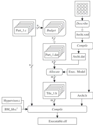
Executable.elf Compile BM lib.c1 Hypervisor.c Tile 1.h Archi.h
Allocate Exec. Model Part 1.dat Archi.dat Compile Archi.xml Describe Budget Part 1.c m m n n n n Fig. 1: Work-flow
Figure 1 summarizes the work-flow and details where the usual practices in the aerospace industry are impacted:
• development phase: each application is implemented as a partition and is provided with a resource budget which consists of hardware capacities description (e.g. number of cores, number of memory banks, . . . ). We assume that all budgets are expressed in a common way and are com-patible with the processor architecture. The budgets are defined independently and no other knowledge about the resources utilizations by others applications is required. The budget definition is done in the Budget phase in Figure 1. Moreover, note that no assumption is made on the type of application (e.g. control-command, data-flow, high performance . . . ).
• integration phase: the integrator must map (Allocate phase in Figure 1) all the applications on the target taking into account application budgets and the hardware capa-bilities. At this step, we produce some target-dependent static and dynamic configurations ensuring the desired temporal isolation during execution.
• run-time (or hypervisor) implementation: must ensure the respect of the budgets given to the applications, even in case of faulty execution by one or several applications. More precisely, the real-time hypervisor is in charge of applying the pre-computed hardware configurations and restraining on-line the execution of the applications to fit into their budget.
Once an application has been implemented following the work-flow, it is predictable in the sense that it behaves temporally exactly the same whether it runs alone on the platform or with other applications. There is no variability due to competitors on the execution time of a task for a given sequence of inputs.
B. Contributions
Because of the diversity of processor architectures, execu-tion models depend greatly on the target. In our case, we consider the KALRAY MPPA R-256 [6] for which we give an
overview in section II.
This paper presents the first and original execution model for time-critical application on the MPPA. Section III describes this execution model along with a formal definition of the notion of application resource budget.
The other contribution of this paper, given in section IV, is the implementation of the execution model which relies on an original hypervisor architecture. To highlight the correctness of the approach, we developed several validation scenarios showing that the temporal isolation is satisfied (see section V). We moreover illustrate the use of the complete work-flow on the ROSACEcase study.
The Allocate phase has been implemented using a constraint programming approach as proposed in [7] with the solver IBM ILOG CPLEX CP Optimizer [8]. Using such techniques for many-core processors restricted with an execution model has been applied in [9]. In this paper, we present a solution to en-sure temporally isolated execution of concurrent applications. The full description of the Allocate phase that precedes the execution is thus out of scope and will be presented in future publications. We examine related works in section VI.
II. PLATFORM DESCRIPTION
Even if an execution model should rely only on very high level architecture-independent concepts, implementations largely depend on the target, due to significant heterogeneity in the architectures of COTS processors. This is the reason why our approach focuses on a specific platform, namely the
KALRAY MPPA R-256 [6]. The selection of the MPPA R-256
was based on the good temporal properties2 of the cores and 2In the context of the CERTAINTY[10] project, AbsInt [11] demonstrated
the property of full timing compositionality of the Kalray k1 VLIW core [12].
low power consumption making it an interesting candidate for the implementation of future avionics systems.
A. General overview
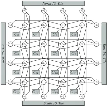
The KALRAY MPPA R-256 integrates 288 cores distributed over 16 Compute tiles and 4 I/O tiles (also denoted as the compute and I/O clusters in KALRAY’s terminology) intercon-nected by a dual Network on Chip (or NoC). Figure 2 shows an overview of the MPPA R-256 architecture. The Compute tiles (Ci) are dedicated to execute user code and the I/O tiles are in charge of managing external peripherals such as the DDR-SDRAM memory. All cores are identical VLIW processors with a private Memory Management Unit (or MMU) enabling virtual addressing and hardware memory protection.
South IO Tile North IO Tile W est I/O T ile East I/O T ile C0 C1 C2 C3 C4 C5 C6 C7 C8 C9 C10 C11 C12 C13 C14 C15 R0 R1 R2 R3 R4 R5 R6 R7 R8 R9 R10 R11 R12 R13 R14 R15 Rn 0 R n 1 R n 2 R n 3 Rs 0 R s 1 R s 2 R s 3 Rw 0 Rw 1 Rw 2 Rw 3 Re 0 Re 1 Re 2 Re 3
Fig. 2:MPPA R-256 architecture overview
B. Compute and I/O tiles
Each Compute tile, drawn in Figure 3, is composed of 16 cores (named PEs), 1 specific core used for resource management (RM), 2MiB of Static Random Access Memory (or SRAM) exclusively accessible by the elements of the tile and 1 DMA engine to transfer data between tiles over the NoC. In the following sections, we will refer to the SRAM memory of the tiles (named SMEM in Kalray’s terminology) as the
local memory in contrast with the external DDRx-SDRAM that is only accessible through the I/O tiles. The local SRAM is divided into 16 banks each of which has a private arbiter in case of concurrent accesses. Parallel accesses to different banks can be issued concurrently without interference.
Each I/O tile has 4 RM cores, 4 DMA engines and some local memory. Moreover, the I/O tiles have access to the external peripherals such as the DDRx-SDRAM or Ethernet controllers. Their main role is to serve the requests from Compute tiles to the external peripherals.
Fig. 3: MPPA R-256 Compute tile overview [12]
C. Network on Chip
All the tiles of the MPPA R-256 are interconnected by two NoCs, one for data transfer (D-NoC), and the other for short control messages (C-NoC). Both NoCs are shaped on the same 2-D torus topology as shown in Figure 2. The user can explicitly choose the route followed by any packet. The D-NoC is based on wormhole switching and offers guaranteed bounds on Worst-Case Traversal Time (or WCTT) in specific configurations (e.g. no deadlock route, flow limitation by the source node, . . . ). This guarantee has been shown using Network Calculus [12].
D. Sources of temporal perturbations
In order to define an adapted execution model, we have to identify any interferences on the target that could violate the temporal isolation of an application. The resources shared between partitions are the memories and the NoC. More precisely,
• local SRAM: an application accessing one local SRAM bank may suffer from a concurrent access to the same bank initiated by a different core running another partition or from a DMA access.
• NoC: several flows sharing some NoC resources will interfere and experience delays. Moreover, in such worm-hole switched NoC, a bad path allocation may result in a deadlock [13] that is obviously unacceptable.
• DDRx-SDRAM: the calculation of tight and safe tim-ing bounds on the external memory strongly depends on the access history. Moreover, an approach based on bandwidth reservation between competitors requires a fine grained analysis of the memory access protocol and possibly strong assumptions on the system model to avoid excessive pessimism.
A more detailed analysis of the aforementioned sources of interference is provided in [14].
III. EXECUTION MODEL
Taking into account the identified interferences, we define an execution model composed of 4 rules.
Rule 1 (Spatial partitioning in compute tiles). In a compute
tile, each local SRAM bank and each core can be reserved by at most one partition.
This rule ensures that a partition executing on a PE will never suffer from local SRAM interferences caused by other partitions. Thanks to that rule, the only potential interferences for one PE accessing a local SRAM bank come either from (1) another PE executing the same partition (which is permitted), (2) the DMA engine or (3) the RM. Any DMA transfer on a bank reserved by a partition only results from that partition’s requests. Therefore, those transfers do not break the temporal isolation. In the same way, the RM, which hosts the hypervisor, only generates traffic linked to the partition.
Rule 2 (TDM scheduling of the NoC). NoC accesses are
time-driven and are performed during strictly periodic slots defined off-line. Overlapping between two NoC paths from two distinct partitions is not allowed.
Time-driven scheduling on the NoC enables an easy, ef-ficient and independent evaluation of the WCTT of packets. In that case, the delay of a message transfer will exhibit no variability regardless of other participants.
Rule 3 (Static buffers). All the buffers transferred during the
strictly periodic NoC slots must be defined off-line.
In the rest of the paper, we will refer to the pre-defined memory areas used by the DMAs to send and receive data as the static buffers. This rule applies whether the static buffer contains code or data. In particular, applications which do not fit inside one compute cluster will have to load their code in this way. Although this rule is not mandatory to fulfill the requirements, it greatly simplifies the implementation of the execution model. The rule also has two orthogonal qualities: (1) it reduces the combinatorial explosion of WCET estimation when using static analysis; (2) it eases the measurement-based validations because the memory coverage is easy to obtain. Rule 4 (Concurrency at DDR-SDRAM level). A bank of the
external DDRx-SDRAM can be shared by several partitions if and only if these partitions never access the DDRx-SDRAM simultaneously.
The rule 4 eliminates inter-partitions interferences at the external memory bank level. This not only gives performance isolation between the partitions accessing the external memory concurrently and eases the estimation of tight bounds on the memory access delay but it can also improve the overall memory throughput because the memory controller will be able to fulfil concurrent accesses mostly with inexpensive memory cycles that do not change pages inside banks.
We can now define precisely the notion of partition resource budget. This is the interface between application designers
and the integrator. The application designer must detail to the integrator the amount of resources needed by its software. In the current version, the budget is close to the hardware detailed capacity. This will be leveraged in future work.
Definition 1. A Partition Node (or PN) represents the need
of processing resource and memory of an application inside one tile. Any application distributed over several tiles must thus include several PNs in its budget. A PN is defined as a tuplehNc, Nbi where Nc andNb respectively are the number
of cores and the number of local memory banks required.
Definition 2. An I/O Node (or I/ON) represents an access
point to the external memory. It is materialized as a processor located on an I/O tile.
Definition 3. A Partition Communication (or PC) represents
a need of communication between two PNs located on two different tiles (or a PN and an I/ON ) in the form of a directed strictly periodic NoC access slot. A PC is defined as the tuple
hsrc, dest, hT, Cii where:
• src (resp. dest) is the source (destination) of the
commu-nication. It can be either a PN or an I/ON.
• hT, Ci is the strictly periodic slot with period T and
durationC 3.
Definition 4. The resource budget of a partition is defined as
the tuple hN , I, C, Bi where N is a finite set of PNs, I is
a finite set of I/ONs, C is a finite set of PCs with src (resp. dest)∈ N ∪ I and B represents a required number of external
DDRx-SDRAM banks.
Example 1. Let us consider two applications appAandappB
whose budgets are:
• budgetA = h {PNA1 = h3, 4i, PN A 2 = h1, 2i}, {I/ON A 1}, {PCA 1 = hPN A 1, PN A 2, h6, 2ii, PC A 2 = hPN A 2, PN A 1, h18, 4ii, PCA 3 = hPN A 2, I/ON A 1, h12, 4ii, }, 2i • budgetB= h {PNB1 = h2, 1i}, {I/ON
B 1}, {PC B 1 = hPN B 1,
I/ONB1, h12, 3ii}, 3i.
The Allocate phase of Fig. 1 is in charge of statically mapping (1) the PNs and I/ONs on specific cores; (2) the banks in specific memory areas; (3) the PCs on precise routes and schedules.
IV. IMPLEMENTATION
We implemented the hypervisor and execution model on the
KALRAY MPPA R-256 in a bare-metal environment to achieve
a fine-grained configuration of the platform. As depicted in Figure 1, the .elf file to be executed embeds both static configuration header files and a hypervisor.
A. Hypervisor
The hypervisor code runs in privileged mode on the RM of each tile and is in charge of applying the correct configurations to the PEs and DMA engines; and of ensuring the respect of 3The offset of the strictly periodic slot is calculated during the Allocate
phase and will be discussed in Section IV-C.
the time-driven NoC schedules. In our implementation, the hypervisor has its own private bank in the local SRAM. This ensures that there is no interference between the hypervisor and applications when accessing the local memory.
1) Synchronization: The time-driven NoC schedule can be implemented only if a global notion of time exists. Fortunately, most many-core processors, including theMPPA R-256, have a common clock ensuring no drift between tiles. Yet, the cores are started independently and the local hardware timestamp counters, even though they do not drift, have unpredictable offsets. We have developed a synchronization algorithm, run at startup, based on round-trip time with I/O tiles and compute tiles to synchronize the hypervisor. Once the synchronization has been completed, no additional communications are re-quired for this purpose any-more.
2) Global tick: In the current implementation, we defined a global tick (denoted as the Systick) of periodTsysactivating periodically the hypervisors of all tiles simultaneously. As explained further in Section IV-C, the NoC communications are evaluated at each hypervisor activation. So, we express the NoC slot durations as a number of Systicks rather than as cycle counts. The value of Tsys should be as small as possible to avoid too coarse roundings of the DMA transfers durations. The low limitation on Tsys is the WCET of the hypervisor as it must have completed before the next Systick. The WCET of the hypervisor occurs when its work load is at the maximum level that is when one single Systick matches at the same time the end of an emission slot, the beginning of the next emission slot, the end of a reception slot and the beginning of the next one. In this case, the hypervisor must notify the emitting partition whose slot is ending, set up the next DMA transfer and notify the receiving partitions of the end and beginning of their respective slots.
In our current implementation, we bound this WCET with a simple measurement-based approach allowing us to reach Tsys = 5µs. The design of a real avionic computer would however probably require a safer WCET estimation. We argue that it can be simply and efficiently achieved (with static analysis for example) since the RM only accesses private memory areas which ensures an execution of the hypervisor that is completely free of external interferences. In this case, the problem is reduced to the WCET estimation of a fully timing-compositional mono-core processor accessing a private SRAM.
B. Rule 1 - Spatial partitioning in compute tiles
This rule states that a static spatial mapping must be applied. The mapping is computed off-line during the Allocate phase of Figure 1. For example 1, PNA
1 of appA is mapped on the PE1, PE2and PE3of compute tile 1 and PNB1 of appBon the PE5and PE6of compute tile 1. The static mapping is applied on the target thanks to a dedicated boot procedure that works as follows:
1) the RM first loads the configuration files which contain the list of local PNs together with their attributes (the list of cores, the list of local SRAM banks).
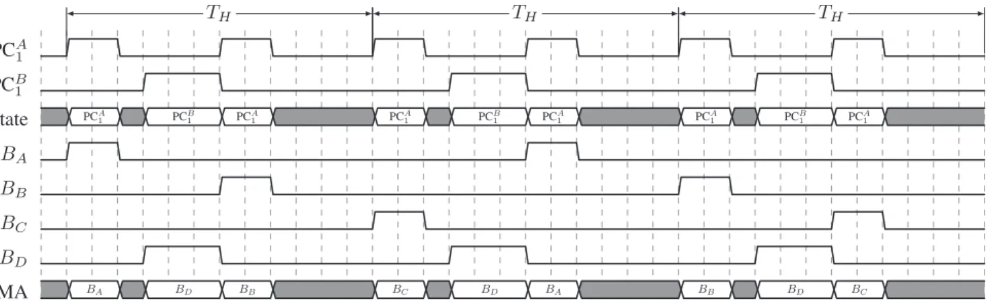
PCA1 PCB 1 State PCA 1 PCB1 PCA1 PCA1 PC1B PCA1 PCA1 PCB1 PCA1 BA BB BC BD DMA BA BD BB BC BD BA BB BD BC TH TH TH
Fig. 4: Example of the NoC time-driven schedule of compute tile 1
2) the local SRAM addressing is configured to the blocked mode by the RM in order to restrict the memory accesses of each application to a pre-defined subset of local banks. Indeed, the interleaved mode allows the traffic to be spread evenly over the banks and thus to maximize the memory throughput, but generates unpredictable interfer-ences.
3) a static MMU configuration is associated to each PE at startup to enable virtual addressing and memory protection. This ensures the allocation of private local memory spaces to partitions and prevents the access to the memory-mapped registers of resources such as the DMA. To achieve this, at startup only, the PEs boot in privileged mode and configure their local MMU before going into user mode and start running the application code. The boot code of the PEs is fixed and cannot be modified by application developers.
We force the execution of user applications (i.e., all ex-cept the hypervisor) in user mode to avoid on-line re-configurations. The Rule 1 avoids local SRAM interferences between different partitions and thus offers temporal isolation within compute tiles. The WCET of applications are thus independent and can be safely bounded thanks to the full timing compositionality property of the KALRAY MPPA R-256 cores demonstrated during the CERTAINTY project [10].
C. Rule 2 - TDM scheduling of the NoC
This rule states that routes on the NoC must be computed off-line and that the schedule must ensure that there is no overlapping of slots on the same link. The schedule is com-puted off-line during the Allocate of Figure 1. More formally, the Allocate phase computes an explicit route and an offset for each PC. Thus each PC, defined as hsrc, dest, {T, C}i (see definition 3) is enriched with an offset O and an ex-plicit route R. We over-load the definition of PC as PCi = hsrci, desti, hTi, Ci, Oii, Rii.
So, for any tile where n PCs [PC1. . . PCn] must be sent, the hypervisor will initiate the corresponding DMA transfers cyclically with a hyperperiod of length:
TH= lcm(Ti), ∀i ∈ N, 0 < i ≤ n
wherelcm(a, b) is the least common multiple of a and b. The scheduling table is stored in memory as an array containing the succession of PCs and idle states during one hyperperiod with the associated durations. There are always two configuration tables: one for emissions and another for receptions. The two tables are independent since the emission and reception of data is full-duplex on theMPPA R-256’ s NoC. For example, table I represents the output configuration of the compute tile 1 with PCA1 and PC
B
1 of example 1 whereTH= lcm(12, 6) = 12. TABLE I: Scheduling table of PCA1 and PC
B 1
Occupant (of the NoC interface) PCA
1 Idle PC B 1 PC
A 1 Idle
Duration (in Systicks) 2 1 3 2 4
At each activation, the hypervisor can start some DMA transfers when entering in a new state of the scheduling table or do nothing if the state remains the same or is idle. Remark 1 (Efficiency of the data structure). The memory
footprint of the scheduling tables depends on the number of transfers during one hyperperiod. The total number of transfers during one hyperperiod is:
Nt = n X i=1 TH Ti
Additionally, there can be at mostNtidle states when there
are no consecutive PCs. So, the number of elements in the array Na is bounded by Na ≤ Nt × 2. We consider that
each element of the array has a size of b bytes. Thus, the
memory footprint f p = Na × b of the scheduling table is
bounded by f p ≤ 2 × Nt × b. The memory efficiency of a
specific configuration can be measured with the indicatorM = Na/n. In the most efficient case, M = 1 and so the number
of elements in the array is exactly equal to the number of PCs. This can happen only when all the PCs have the same period and when the utilization of the DMAU =PCi/Ti= 1
D. Rule 3 - Static buffers
For each PC, The hypervisor knows the list of associated
static buffers which must be sent or received via the network slots. Each buffer is defined by:
Bx= hLx, Rx, Sxi with
• Lx is the address in the src’s virtual address space. If the buffer must be sent (rather than received) from the tile, then src is the partition and Lx is the address to be read in the local partition’s virtual address space. If the buffer must be received, there are two cases: src can be an I/ON or a remote PN. If src is an I/ON , thenLxis the address to be read in the DDRx-SDRAM. Otherwise,Lx is the address to be read in the remote partition’s virtual address space;
• Rx is the address in the dst’s virtual address space. The same reasoning as forLxapplies;
• Sx is the size of the buffer in bytes.
The hypervisor is in charge of selecting a correct buffer at the beginning of a slot and of configuring the DMA engine accordingly to send (resp. receive) it. In our current implementation, the hypervisor sends (or receives) exactly one buffer per slot (but this could be implemented differently). So, whenn different buffers must be sent (or received), it will take n slots.
Example 2. We use the budgets defined in the Example 1.
PCA1 is associated with three static buffers BA,BB andBC
and PCB
1 is associated with only one static bufferBD. Figure
4 depicts the transfer of those buffers from compute tile 1. We can see BA,BB and BC are transferred by the DMA every
three activations of PCA1 while BD is sent at each activation
of PCB1.
E. Rule 4 - Concurrency at DDR-SDRAM level
We rely on the time-triggered NoC schedule to avoid the interferences at the external memory level by construction. Indeed, the NoC schedule is computed not only with a non-overlapping constraint for PCs sharing some NoC resources but also with DDR-related constraints. Thereby, we ensure that no PCs belonging to partitions sharing a bank in DDR can target simultaneously I/ONs linked with the same memory controller.
V. VALIDATION
In order to validate the correctness of our approach, we show experimentally the property of strong temporal isolation between partitions. For that purpose, the validation procedure is organized as follows:
• a reference application has been developed with the work-flow. The execution times of this application are measured with hardware counters and logged for post processing. • several concurrent applications in other partitions are
executed in parallel. We run several scenarios where the configurations of the competitors vary widely.
We observe that the execution times of the reference appli-cation are always equivalent and do not depend on the test scenario. This highlights the insensitivity of the reference application to the behaviour of the competitors. Such an approach based on benchmarking is standard: even though it is not possible to prove complete coverage, the works of [15], [16] give means to improve the stressing benchmarks tracking.
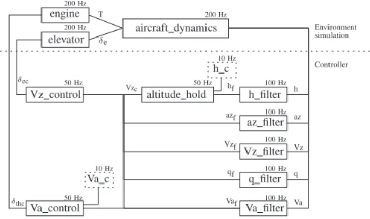
engine elevator aircraft dynamics Vz control Va control h filter az filter Vz filter q filter Va filter altitude hold Va c h c Environment simulation Controller 10 Hz 10 Hz 50 Hz 50 Hz 50 Hz 100 Hz 100 Hz 100 Hz 100 Hz 100 Hz 200 Hz 200 Hz 200 Hz δthc Vzc δec hf h azf az Vzf Vz qf q Vaf Va T δe
Fig. 5: Controller architecture
A. Reference application : the ROSACEcase study
As reference application, we use the longitudinal flight controller of the Research Open-Source Avionics and Control Engineering (or ROSACE) case study [17]. Although of modest size, the ROSACEcontroller is representative of real avionics applications and introduces complex multi-periodic execution patterns.
PE1 engine h filter Va control PE2 elevator a/c dynamics az filter altitude hold Vz control
PE3 q filter
PE4 Va filter
PE5 Vz filter
Fig. 6: Scheduling of the ROSACEcontroller
1) Architecture of the application: As shown in Figure 5, the application is composed of the following parts:
• The simulation environment is the discretized model of the aircraft composed of three blocks (engine, elevator and aircraft dynamics).
• The controller is composed of three sub-controllers (Va control, Vz control and altitude hold) and 5 filters. • The simulated scenarios consist in sending different pilot
instructions to change the flight level.
2) Implementation choices: We placed the whole ROSACE
application inside one PN as it can easily fit in one compute tile. We leveraged the relative independence of some basic blocks (meaning that they are not subject to precedence constraints) to produce the parallel schedule depicted in Figure
6. This schedule uses 5 PEs and the compiled executable can fit into 3 local SRAM banks.
However, in order to have a multi-tile application (that is more interesting for our experiments), we added a Set Point
Generator (or SPG). The SPG produces on-line the pilot commands (hc,VzcandVac) used by the controller to execute
the scenarios. We place the SPG in a second PN. As shown in Figure 7, we define three PCs. The first PC provides the SPG commands to the controller at a 10Hz frequency. The second PC transfers the output values (Vz,Va,h, az andq) from the controller to the SPG. And the third sends the output values from the SPG to the DDR memory at a 200Hz frequency. We measure on-line the execution times of the basic blocks of
ROSACEthanks to the PEs hardware cycle counters and we
log them for post-processing. The log procedure is detailed in Section V-C3. The PNs and PCs of the ROSACEpartition are detailed in the tables II and III.
SPG ROSACE C0 C2 IO1 DDRx-SDRAM PC2/ 200Hz PC1/ 10Hz PC 3 / 200Hz
Fig. 7: Example of implementation of the ROSACEcase study
TABLE II: PNs of the ROSACEpartition
Name Number of PEs Local SRAM banks
ROSACE 5 3
SPG 1 1
TABLE III: PCs of the ROSACEpartition
Name srci desti Ti(in Systicks) Ci(in Systicks)
P C1 SPG ROSACE 20000 1 P C2 ROSACE SPG 1000 1
P C3 SPG IO1 1000 1
B. Concurrent application
The concurrent application is based on a simple image inversion algorithm. This choice is motivated by the following reasons:
• the parallelization of this algorithm over several PEs is simple and configurable;
• the memory utilization is manageable by choosing pic-tures of appropriate sizes;
• the NoC budgets can easily be adjusted to deal with pic-tures of different sizes and various periods of execution; • and the implementation is rather simple.
1) Architecture of the application: The application is exe-cuted cyclically at a configurable period. It has in memory 3 buffers of equal size. At the beginning of each cycle, one or several cores run the image inversion algorithm on a picture stored in one of the 3 buffers. Meanwhile, another picture is being received in one of the two remaining buffers, and the third buffer is being sent by the DMA. At the next cycle, the cores will apply the algorithm on the previously received image. The previously computed image is sent and another image is received in the third buffer.
2) Implementation choices: We consider 8 bit grey-scale pictures of fixed size (512x512 or 256x256 or 128x128 configurable off-line). The algorithm can be configured to be executed by 16, 8, 4 or 2 PEs. Each instance of the application is placed into 1 PN. Each PN sends and receives pictures through two PCs (an incoming one and an outgoing one). The length of the PCs are fixed by the pictures sizes. Several identical (same number of PEs, same picture size, same PCs lengths and periods) instances can cohabit in one partition and exchange data (the outgoing PC of one PN is the receiving PC of another).
C. Means of observation
Overall, the tight observation of a COTS-based system is challenging. Indeed, intrusive observation through JTAG for example can introduce unmanaged delays causing deadline misses. Thus, this problematic should be taken into account early in the development phase to include the means of observation into the applications themselves. For example, one may provide some PCs dedicated to logging or over-provision the resource budget to account for the observation-related delays. We present 3 additional observation and validation means that helped us in our experiments.
1) Post-processing of the memory footprints: The develop-ment environdevelop-ment of theMPPA R-256 allows dumping of both local and external memories after the end of an execution. Hence, the final real memory footprints of the applications can be compared with the expected ones in order to look for differences. If none are spotted, there are no proof of the correct execution but it is certainly encouraging. Otherwise, the differences are usually very helpful for investigation. We used this method to verify the functional behaviour of ROSACE
by checking that the output values, written in the external memory, match the outputs of the implementation proposed in [17].
2) Non-intrusive on-line observation of the memory ac-cesses: We used a DDR-SDRAM protocol analyzer which significantly helped the validation of both the applications and the execution model. Indeed, such hardware is able to sniff the commands going from the DDR-SDRAM controller to the memory modules thanks to a physical interposer placed between the modules and the slots. Although physical equip-ment is required, the memory accesses do not suffer from additional delays and the on-line observation is completely non-intrusive. The captured data contains the logs of the commands (read, write, activate, precharge, refresh, ...) with
the corresponding addresses and a cycle accurate timestamp and possibly the value of the data depending on the analyzer. As long as the memory spaces of partitions do not overlap (this is not mandatory to fulfill the requirements of the execution model but it is useful for this specific setup), the address of any command can be associated easily to its initiating partition. So, we checked temporal properties on the traces of memory accesses of each partition in order to: 1) validate the behaviour of an application by checking that it is doing the right memory transaction at the expected time; and 2) validate the execution model compliance, and especially the Rule 4, by checking the non-overlapping of memory transactions coming from partitions sharing a DDR-SDRAM bank.
3) The log server: The C-NoC of the MPPA R-256 offers
the possibility of sending small asynchronous messages. We used it to implement a simple log feature. We reserved one of the compute tiles to execute a specific application denoted as the Log Server which simply waits for the reception of C-NoC messages and writes them back into its local SRAM. A PC from the Log Server to an I/ON is reserved to periodically flush the received data into the external memory. Hence, any application can log information data asynchronously by sending them to the Log Server. Yet, the log procedure has two main drawbacks. Firstly, it can loose packets. On theMPPA R
-256, the C-NoC reception queues can store only one message at a time. So, any untreated message can be lost during the reception of a new message. The quantity of lost packets can nonetheless be retrieved from the hardware packet counters and can be used to determine whether a specific log trace can be trusted as it is or not. And secondly, it is intrusive. Sending C-NoC packets takes time. This must be carefully taken into account in a time-triggered environment.
In practice, we used the Log Server to get the execution times of the basic blocs of ROSACE as explained in Sec-tion V-A2.
D. Experimental results
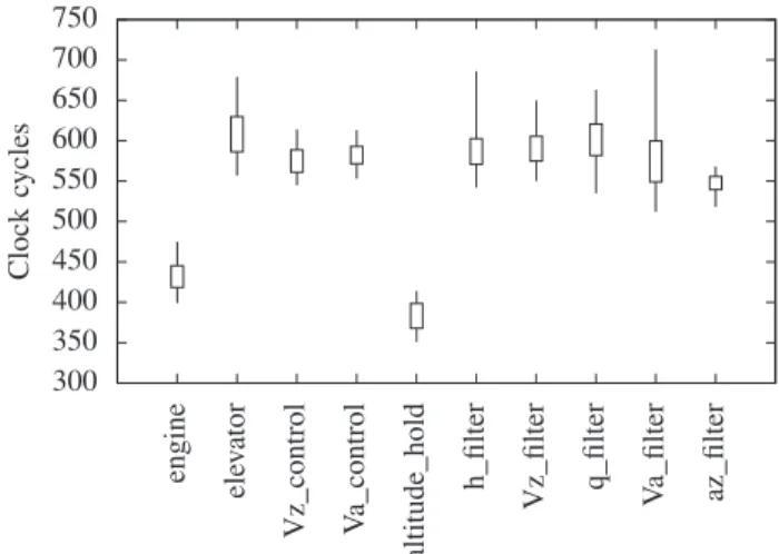
Scenario 1: no interference: At first, we execute ROSACE
with no competitors on theMPPA R-256 in order to define the
reference values that must be respected by the other scenarios introducing interferences. Figure 7 depicts the mapping of
ROSACE on the MPPA R-256 provided automatically by our
mapping algorithm mentioned in Section I. The SPG is placed on the compute tile 0, ROSACE is placed on compute tile 2 and the access to the external memory is provided by the north I/O tile. This configuration for ROSACEwill be similar in all the following scenarios. We provide in Figure 8 a candlestick chart representing the execution times in machine cycles of the basic blocs of ROSACE. The lines represent the minimum and maximum values and the boxes the standard deviations. The values are obtained after at least 10,000 executions of each basic bloc. The execution times of the aircraft dynamics bloc have an average of 59895 clock cycles so we do not plot them for clarity.
Scenario 2: NoC interferences: The concurrent application is composed of two instancesI1andI2of the image inversion
300 350 400 450 500 550 600 650 700 750 engine ele v ator Vz control V a control altitude hold h filter Vz filter q filter V a filter az filter Clock cycles
Fig. 8: Execution times of ROSACE
algorithm with 512x512 pictures processed by 8 PEs. Each instance is placed in a PN requiring 8 cores and 7 local SRAM banks (exactly 6 banks for the image buffers and 1 bank for the code and other data). The 2 PNs are linked by two PCs of arbitrary period Ti = 2ms and length Ci = 300µs (deduced from the NoC bandwidth and the image sizes). We forced the mapping algorithm to placeI1andI2respectively on compute tiles 3 and 4 and to provide partially common NoC paths between the two partitions. The configuration of ROSACE
remains the same. In this context, the measured execution times of the basic blocs of ROSACE are very close to those observed during the Scenario 1:
• the best and worst measured times were the same in the two cases;
• the averages of the two vectors differ by less than 1%. Moreover, we modified the hypervisor of tile 2 to log the current date when receiving a NoC packet. We observed that 100% of the packets received by tile 2 arrived during the in-tended reception slots. This exhibits the good synchronization between the tiles and that the data sent by the SPG were never delayed by the packets of the concurrent application.
Scenario 3: DDRx-SDRAM interferences: The concurrent application is composed of only one instance of the image processing algorithm with a PN configuration similar to that of Scenario 2. The PN receives/sends data from/to the external DDRx-SDRAM with 2 PCs configured as in Scenario 2. The PN is placed on tile 1 and the image buffers in DDR are located on a shared bank with ROSACE. Once again, the execution times of the basic blocs of ROSACEare very close to those observed during Scenario 1 (in the same proportions as those of Scenario 2). We modified the hypervisor of tile 1 to log the reception dates of NoC packets as we did in Scenario 2 and we observed that all the packets arrived within the appropriate slots despite the shared DDR-SDRAM bank.
VI. RELATED WORK
A. Execution models
Several execution models have been proposed for multi-core platforms, most of them based on time triggered steps. The main ideas are:
• assume a TDMA access on the internal bus (e.g. [18]), • modify the application architecture and decompose it into
several phases such as pure execution or access to data which are not in the caches. Then schedule the different phases so as to calculate statically all the conflicts (e.g. [4], [19]–[21]).
The case of many-core has been less studied in the literature. We reused common ideas with former execution models: (1) applications are spatially mapped off-line (the maximum sections are stored in the local memory, thanks to the local memory architecture); (2) accesses on the shared resources are made in a time-driven manner; (3) all mappings, schedules and network routes are computed off-line. The novelties concerns the tight management of the network and of the overall complexity of the MPPA R-256.
B. Run-time ensuring temporal isolation
Another approach instead of modifying the applications is to force them to access on the bus or memory at specific time or with a given bandwidth. To do that, a specific run-time must be developed such as MEMGUARD[22], the run-time of [23]
or MARTHY[24].
Our approach mixed the notion of execution model and the development of a hypervisor which forces the applications to comply with the rules. Our hypervisor is close to MARTHYin the sense that the DMA (instead of the MMU) is modified reg-ularly to constrain the behaviour. In [25], Girbal et al. provide a detailed comparison of both the existing execution models and run-times restricting the accesses of applications to the shared resources of multi-cores in order to master the interferences. However, none of the approaches consider NoC-based many-core processors with fully explicit communications and are thus not applicable the to KALRAY MPPA R-256.
C. Work-flow
In [26], the authors present a work-flow for mapping real-time tasks on NoC-based many-core processors. Similarly to us, the authors took into account the low level hardware particularities of their target to build efficient scheduling tables that are not directly applicable to the KALRAY MPPA R-256. Moreover, the authors do not aim at providing temporally isolated partitions and do not consider applications of different criticality levels. In [27], the authors presented a problem of computing time-triggered communications scheduling on a TTEthernet network and solved it with Satisfiability Modulo Theories (SMT). The problem is similar to our mapping time-triggered communications on the NoC, but we manage in addition independent routes and memory mappings. An empirical study on the scalability of constraint solving for off-line real-time scheduling can be found in [28].
D. Temporally guaranteed services on the NoC
In our approach, we consider a time-triggered NoC schedule enabling an easy evaluation of the WCTT of packets. Such schedules have already been deployed in the industry with the FlexRay [29] and TTEthernet [30] standards to interconnect real-time systems. However, most of the available NoC-based many-core COTS processors such as the KALRAY MPPA R-256 or the EZCHIPTILEGX* [31] and TILEMX* [32] families do not have native hardware support for TDM scheduling. So, many contributions in the literature consider asynchronous sources and highlight the benefit of such a more flexible model. In a hard real-time context, the authors often use Network Calculus [33], [34] and Real-Time Calculus [35] to provide temporally guaranteed services. The application of such the-ories has been proven to be applicable for NoCs in [36] and successfully applied on the KALRAY MPPA R-256 in [12]
and [37]. In general, these techniques are based on the property of Timing Compositionality in the sense that the temporal behaviour of the NoC can be inferred from the contribution of all participants [38]. By using a time-triggered schedule, we aim at the property of Timing Composability (also defined in [38]) that is orthogonal to timing compositionality but better suited to ensure a strict temporal isolation, including the need of separated verifications of the timing behaviours of the partitions.
Some academic initiatives are based on TDM scheduled NoCs such as T-CREST with the Argo NoC [39] or CompSOC with Aethereal [40]. In our case, the TDM schedule is com-pletely enforced by software by leveraging the global clock available in the KALRAY MPPA R-256 to reach easily a global
notion of time. In this direction, the closest contribution to our work is the one presented in [41]. However, the authors only consider bus-based or crossbar-based interconnects while our approach takes benefit from the degree of parallelism exploitable from a NoC-based platform.
E. Predictable accesses to DDRx-SDRAM
The DDRx-SDRAM access protocol described in the JEDEC standard [42] is complex and highly depends on the state of the hardware. The problem of achieving pre-dictable memory transactions is addressed in three ways in the literature. The first solution is based on the utilization of custom memory controllers designed for real-time such as AMC [43], PREDATOR [44], PRET [45] or ROC [46]. Although custom controllers surely offer the most elegant solution, COTS controllers are preferable in the industry since they allow to reduce both the non-recurring costs and the time-to-market.
A second solution, applicable to COTS, relies on an ac-curate analysis of the DDRx-SDRAM access protocol. The calculation of tight bounds on the memory access time within the specific context of multi-core COTS processors is still an active research topic [47]–[50]. To the best of our knowledge, no contribution considers many-core processors where the memory transactions are not due to cache refills or evictions
but to DMA transfers that are more likely to be large and are explicitly initiated by software.
A third solution is based on software approaches where the scheduler or the OS is memory-aware and orders the accesses to avoid interferences [22], [51]. In the idea, the closest contribution to our work for the DDRx-SDRAM management is the TDMA-based memory-centric scheduling of Yao et al. in [52].
VII. CONCLUSION
In this paper, we presented an execution model allowing the mapping of temporally isolated partitions on the KALRAY MPPA R-256. We detailed its dual implementation composed
of: 1) pre-computed static hardware configurations providing an intra-tile temporally isolated environment to partitions; 2) a real-time hypervisor limiting the behaviours of the applications on-line, especially to ensure the respect of the time-triggered NoC schedule. We implemented an academic case study and we have shown the effective temporal isolation between parti-tions with several experimental validation scenarios involving sharing at the NoC and DDRx-SDRAM levels.
In the future, we will introduce new features to the hypervi-sor such as the online management of best-effort NoC traffic to fill the partially unused slots. We are also considering the problem of the automatic budgeting of partitions that seems feasible for many types of applications having an intrinsically cyclic architecture (e.g., control-command). Finally, we will evaluate the capability of our approach to deal with problems of industrial size by implementing a real avionic application from Airbus.
REFERENCES
[1] Radio Technical Commission for Aeronautics (RTCA) and EURopean Organisation for Civil Aviation Equipment (EUROCAE), DO-297:
Software, Electronic, Integrated Modular Avionics (IMA) Development Guidance and Certification Considerations, Std.
[2] ——, DO-178C: Software Considerations in Airborne Systems and
Equipment Certification, Std., 2011.
[3] R. Wilhelm and J. Reineke, “Embedded systems: Many cores - many problems,” in 7th IEEE International Symposium on Industrial
Embed-ded Systems (SIES’12), 2012, pp. 176–180.
[4] E. Betti, S. Bak, R. Pellizzoni, M. Caccamo, and L. Sha, “Real-Time I/O Management System with COTS Peripherals,” IEEE Transactions
on Computers, vol. 62, no. 1, pp. 45–58, 2013.
[5] A. Abel, F. Benz, J. Doerfert, B. D¨orr, S. Hahn, F. Haupenthal, M. Ja-cobs, A. H. Moin, J. Reineke, B. Schommer, and R. Wilhelm, “ Impact of Resource Sharing on Performance and Performance Prediction: A Survey ,” in 24th International Conference on Concurrency Theory
(CONCUR’13), 2013, pp. 25–43.
[6] Kalray, The MPPA hardware architecture, 2012.
[7] C. Ekelin, “An Optimization Framework for Scheduling of Embedded Real-Time Systems,” Ph.D. dissertation, Chalmers University of Tech-nology, 2004.
[8] IBM ILOG, “CPLEX Optimization Studio,” 2014,
http://www.ibm.com/software/integration/optimization/cplex-optimization-studio/.
[9] W. Puffitsch, ´E. Noulard, and C. Pagetti, “Off-line mapping of multi-rate dependent task sets to many-core platforms,” Real-Time Systems, vol. 51, no. 5, pp. 526–565, 2015.
[10] “FP7 Certification of Real-Time Applications Designed for Mixed-Criticality (CERTAINTY),” http://www.certainty-project.eu/.
[11] AbsInt Angewandte Informatik GmbH, http://www.absint.com.
[12] B. De Dinechin, D. van Amstel, M. Poulhies, and G. Lager, “Time-critical computing on a single-chip massively parallel processor,” in
18th Design, Automation & Test in Europe Conference and Exhibition (DATE’14), 2014, pp. 1–6.
[13] ´E. Fleury and P. Fraigniaud, “A General Theory for Deadlock Avoidance in Wormhole-Routed Networks,” IEEE Transactions on Parallel and
Distributed Systems, vol. 9, no. 7, pp. 626–638, 1998.
[14] Q. Perret, P. Maur`ere, ´E. Noulard, C. Pagetti, P. Sainrat, and B. Triquet, “Predictable composition of memory accesses on many-core processors,” in 8th Conference on Embedded Real Time Software and Systems
(ERTS’16), 2016.
[15] J. Nowotsch and M. Paulitsch, “Leveraging multi-core computing architectures in avionics,” in 9th European Dependable Computing
Conference (EDCC’12), 2012, pp. 132–143.
[16] J. Bin, S. Girbal, D. Gracia Prez, A. Grasset, and A. Merigot, “Studying co-running avionic real-time applications on multi-core COTS architec-tures,” in 7th Conference on Embedded Real Time Software and Systems
(ERTS’14), 2014.
[17] C. Pagetti, D. Saussie, R. Gratia, ´E. Noulard, and P. Siron, “The ROSACE case study: From simulink specification to multi/many-core execution,” in 20th Real-Time and Embedded Technology and
Applica-tions Symposium (RTAS’14), 2014, pp. 309–318.
[18] S. Chattopadhyay, A. Roychoudhury, and T. Mitra, “Modeling shared cache and bus in multi-cores for timing analysis,” in 13th International
Workshop on Software Compilers for Embedded Systems (SCOPES’10), 2010, pp. 1–10.
[19] R. Pellizzoni, E. Betti, S. Bak, G. Yao, J. Criswell, M. Caccamo, and R. Kegley, “A Predictable Execution Model for COTS-based Embedded Systems,” in 17th IEEE Real-Time and Embedded Technology and
Applications Symposium (RTAS’11), 2011, pp. 269–279.
[20] F. Boniol, H. Cass´e, ´E. Noulard, and C. Pagetti, “Deterministic Execu-tion Model on COTS Hardware,” in 25th InternaExecu-tional Conference on
Architecture of Computing Systems (ARCS’12), 2012, pp. 98–110. [21] G. Durrieu, M. Faug`ere, S. Girbal, D. Gracia P´erez, C. Pagetti, and
W. Puffitsch, “Predictable Flight Management System Implementation on a Multicore Processor,” in 7th Conference on Embedded Real Time
Software and Systems (ERTS’14), 2014.
[22] H. Yun, G. Yao, R. Pellizzoni, M. Caccamo, and L. Sha, “Mem-Guard: Memory bandwidth reservation system for efficient performance isolation in multi-core platforms,” in 19th Real-Time and Embedded
Technology and Applications Symposium (RTAS’13), 2013, pp. 55–64. [23] J. Nowotsch, M. Paulitsch, D. B¨uhler, H. Theiling, S. Wegener, and
M. Schmidt, “Multi-core interference-sensitive WCET analysis leverag-ing runtime resource capacity enforcement,” in 26th Euromicro
Confer-ence on Real-Time Systems (ECRTS’14), 2014, pp. 109–118. [24] X. Jean, D. Faura, M. Gatti, L. Pautet, and T. Robert, “Ensuring robust
partitioning in multicore platforms for IMA systems,” in 31st IEEE/AIAA
Digital Avionics Systems Conference (DASC’12), 2012, pp. 7A4–1– 7A4–9.
[25] S. Girbal, X. Jean, J. le Rhun, D. G. Prez, and M. Gatti, “Deterministic Platform Software for Hard Real-Time systems using multi-core COTS,” in 34th Digital Avionics Systems Conference (DASC’15), 2015. [26] T. Carle, M. Djemal, D. Potop-Butucaru, and R. De Simone, “Static
mapping of real-time applications onto massively parallel processor arrays,” in 14th International Conference on Application of Concurrency
to System Design (ACSD’14), 2014, pp. 112–121.
[27] S. S. Craciunas and R. S. Oliver, “SMT-based Task- and Network-level Static Schedule Generation for Time-Triggered Networked Systems,” in 22nd International Conference on Real-Time Networks and Systems
(RTNS’14), 2014, pp. 45:45–45:54.
[28] R. Gorcitz, E. Kofman, T. Carle, D. Potop-Butucaru, and R. De Simone, “On the Scalability of Constraint Solving for Static/Off-Line Real-Time Scheduling,” in 13th International Conference on Formal Modeling and
Analysis of Timed Systems (FORMATS’15), 2015, pp. 108–123. [29] International Organization for Standardization (ISO), ISO 17458, Road
vehicles – FlexRay communications system, Std. [30] SAE International, AS6802: Time-Triggered Ethernet, Std. [31] EZchip, TILE-Gx72 Processor - Product Brief.
[32] Bob Doud, “Accelerating the Data Plane With the TILE-Mx Manycore Processor,” February 2015, Linley Data Center Conference.
[33] J.-Y. Le Boudec and P. Thiran, Network Calculus: A Theory of
Deter-ministic Queuing Systems for the Internet. Springer-Verlag, 2001. [34] R. Cruz, “A calculus for network delay. I. network elements in isolation,”
IEEE Transactions on Information Theory, vol. 37, no. 1, pp. 114–131, 1991.
[35] L. Thiele, S. Chakraborty, and M. Naedele, “Real-time calculus for scheduling hard real-time systems,” in 2000 International Symposium
on Circuits and Systems (ISCAS’00), vol. 4, 2000, pp. 101–104. [36] Y. Qian, Z. Lu, and W. Dou, “Analysis of worst-case delay bounds for
on-chip packet-switching networks,” IEEE Transactions on
Computer-Aided Design of Integrated Circuits and Systems, vol. 29, no. 5, pp. 802–815, 2010.
[37] G. Giannopoulou, N. Stoimenov, P. Huang, L. Thiele, and B. D. de Dinechin, “Mixed-criticality scheduling on cluster-based manycores with shared communication and storage resources,” Real-Time Systems, pp. 1–51, 2015.
[38] S. Hahn, J. Reineke, and R. Wilhelm, “Towards compositionality in execution time analysis: Definition and challenges,” SIGBED Review, vol. 12, no. 1, pp. 28–36, 2015.
[39] E. Kasapaki and J. Spars, “Argo: A Time-Elastic Time-Division-Multiplexed NOC Using Asynchronous Routers,” in 20th IEEE
Interna-tional Symposium on Asynchronous Circuits and Systems (ASYNC’14), 2014, pp. 45–52.
[40] K. Goossens, J. Dielissen, and A. Radulescu, “Aethereal network on chip: concepts, architectures, and implementations,” IEEE Design & Test
of Computers, vol. 22, no. 5, pp. 414–421, 2005.
[41] M. Ziccardi, A. Cornaglia, E. Mezzetti, and T. Vardanega, “Software-enforced Interconnect Arbitration for COTS Multicores,” in 15th
Inter-national Workshop on Worst-Case Execution Time Analysis (WCET’15), vol. 47, 2015, pp. 11–20.
[42] JEDEC, “DDR3 SDRAM STANDARD,” 2012.
[43] M. Paolieri, E. Quiones, F. Cazorla, and M. Valero, “An Analyzable Memory Controller for Hard Real-Time CMPs,” IEEE Embedded
Sys-tems Letters, vol. 1, no. 4, pp. 86–90, 2009.
[44] B. Akesson, K. Goossens, and M. Ringhofer, “PREDATOR: A
Pre-dictable SDRAM Memory Controller,” in 5th IEEE/ACM International
Conference on Hardware/Software Codesign and System Synthesis (CODES+ISSS’07), 2007, pp. 251–256.
[45] J. Reineke, I. Liu, H. D. Patel, S. Kim, and E. A. Lee, “PRET DRAM Controller: Bank Privatization for Predictability and Temporal Isolation,” in 7th IEEE/ACM/IFIP International Conference on Hardware/Software
Codesign and System Synthesis (CODES+ISSS’11), 2011, pp. 99–108. [46] Y. Krishnapillai, Z. P. Wu, and R. Pellizzoni, “A Rank-Switching, Open-Row DRAM Controller for Time-Predictable Systems,” in 26th
Euromicro Conference on Real-Time Systems (ECRTS’14), 2014, pp. 27–38.
[47] H. Kim, D. de Niz, B. Andersson, M. Klein, O. Mutlu, and R. R. Rajku-mar, “Bounding memory interference delay in COTS-based multi-core systems,” in 20th Real-Time and Embedded Technology and Applications
Symposium (RTAS’14), 2014, pp. 145–154.
[48] H. Yun, R. Pellizzoni, and P. K. Valsan, “Parallelism-Aware Memory Interference Delay Analysis for COTS Multicore Systems ,” in 27th
Euromicro Conference on Real-Time Systems (ECRTS’15), 2015, pp. 184–195.
[49] Z. P. Wu, Y. Krish, and R. Pellizzoni, “Worst Case Analysis of DRAM Latency in Multi-requestor Systems,” in 34th Real-Time Systems
Symposium (RTSS’13), 2013, pp. 372–383.
[50] R. Pellizzoni, A. Schranzhofer, J.-J. Chen, M. Caccamo, and L. Thiele, “Worst case delay analysis for memory interference in multicore sys-tems,” in 13th Design, Automation & Test in Europe Conference and
Exhibition (DATE’10), 2010, pp. 741–746.
[51] G. Yao, R. Pellizzoni, S. Bak, H. Yun, and M. Caccamo, “Global Real-Time Memory-Centric Scheduling for Multicore Systems,” IEEE
Transactions on Computers, (accepted, to appear).
[52] G. Yao, R. Pellizzoni, S. Bak, E. Betti, and M. Caccamo, “Memory-centric Scheduling for Multicore Hard Real-time Systems,” Real-Time
![Fig. 3: MPPA
R -256 Compute tile overview [12]](https://thumb-eu.123doks.com/thumbv2/123doknet/3168733.90393/4.892.94.412.133.414/fig-mppa-r-compute-tile-overview.webp)