O
pen
A
rchive
T
OULOUSE
A
rchive
O
uverte (
OATAO
)
OATAO is an open access repository that collects the work of Toulouse researchers and
makes it freely available over the web where possible.
This is an author-deposited version published in :
http://oatao.univ-toulouse.fr/
Eprints ID : 18801
The contribution was presented at RTNS 2016 :
http://rtns16.univ-brest.fr/#page=home
To cite this version :
Perret, Quentin and Maurere, Pascal and Noulard, Eric and
Pagetti, Claire and Sainrat, Pascal and Triquet, Benoît Mapping hard real-time
applications on many-core processors. (2016) In: 24th International Conference on
Real-Time and Network Systems (RTNS 2016), 19 October 2016 - 21 October 2016
(Brest, France).
Any correspondence concerning this service should be sent to the repository
administrator:
[email protected]
Mapping hard real-time applications on many-core
processors
Quentin Perret
Airbus Operations S.A.S. Toulouse, France
Pascal Maurère
Airbus Operations S.A.S. Toulouse, France
Éric Noulard
DTIM, UFT-MiP, ONERA Toulouse, France
Claire Pagetti
DTIM, UFT-MiP, ONERA Toulouse, France
Pascal Sainrat
IRIT, UFT-MiP, UPS Toulouse, France
Benoît Triquet
Airbus Operations S.A.S. Toulouse, France
ABSTRACT
Many-core processors are interesting candidates for the de-sign of modern avionics computers. Indeed, the computa-tional power offered by such platforms opens new horizons to design more demanding systems and to integrate more ap-plications on a single target. However, they also bring chal-lenging research topics because of their lack of predictability and their programming complexity. In this paper, we focus on the problem of mapping large applications on a com-plex platform such as the Kalray mppa R-256 while
main-taining a strong temporal isolation from co-running appli-cations. We propose a constraint programming formulation of the mapping problem that enables an efficient paralleliza-tion and we demonstrate the ability of our approach to deal with large problems using a real world case study.
1.
INTRODUCTION
Many-core processors are a potential technology for aerospace industry as long as there is a way to certify them according to aeronautics standards, in particular with:
• DO 178 B/C [25] which imposes that the WCET of any application can be computed;
• DO 297 [24] which states that mixed-critical applica-tions can execute on the same resource as long as they are strongly segregated, in the sense that an applica-tion cannot interfere with others even in the presence of failures;
• CAST-32 [5] and FAA white paper [13] which detail how temporal interferences affect the safety and why mitigation means against those interferences are manda-tory, when executing on multi-core COTS processors. Because of the architecture of many-core chips, computing WCET requires to be able to bound safely the interference delays on shared resources [26] meanwhile ensuring segrega-tion imposes that execusegrega-tion times must not vary whatever the co-running applications do.
1.1
Temporal isolation-based framework
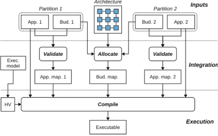
The overall framework workflow is shown in Figure 1. When implementing several applications on the same target (single or multi/many-core chips), two stakeholders inter-act: on the one hand, the application designers are in charge of developing their application and on the other hand, the platform integrator is in charge of integrating the different applications on the shared platform.
Figure 1: Workflow
In [19], we proposed an approach to implement real-time safety-critical applications on a many-core target in such a way that strict temporal guarantees are ensured whatever the behaviour of other applications sharing the resources is. The approach is based on a four-rules execution model to be followed by the developers (application designers and plat-form integrator) to avoid any unpredictable or non-segregated behaviours. Some of the rules are enforced by an off-line mapping and computation, while others are ensured by a bare-metal hypervisor that we developed. That initial work concerned mostly the activities of the platform integrator. More precisely, given an abstract view of applications in the form of a set of application budgets, the integrator maps off-line during the Allocate phase the budgets on the target, while respecting the execution model. The output is both the computed mapping and the associated code (memory allocation, boot code of the cores and schedule of budgets). Given the application internal execution in the budget, the applications can then run on the target.
1.2
Contribution
In this paper, we focus on the application designers ac-tivity which is modified due to the use of a many-core plat-form. The purpose is to help them provide their budget. More specifically, each application (App) is defined as a set of multi-periodic communicating tasks and is wrapped in a single partition. A partition also contains an application budget (Bud ) which is an abstraction of the application that represents the needs in terms of resources (memory, CPU, communication and IOs). The budget is the interface format between the application designer and the platform integra-tor. Indeed, the latter does not need a complete knowledge of each application to share the platform.
Before explaining how to obtain a budget, we first recall the platform model, the execution model and the application definition in section 2. We then detail some basic formulas to derive a minimal budget (see section 3). However, it is up to the application designer to define its budget. Then, we propose a constraint programming approach to validate a given budget (see section 4). A budget is considered as valid when it enables a correct implementation of the appli-cation for both functional and non-functional requirements. During the validate phase, we compute a complete sched-ule of the application in its budget. This schedsched-ule can be distributed over several cores and includes not only the map-ping of tasks on cores but also the tight management of the communication over the Network on Chip (NoC). Once a correct schedule has been found, the user can then decide to keep it or to optimize it by changing some parameters (ex: the number of cores, the length of the time-slices, . . . ). A second output is the internal budget code. In section 5, we illustrate the applicability and the scalability of the con-straint programming approach. We then present the related work and conclude.
2.
SYSTEM MODEL
2.1
Hardware platform
2.1.1
Overview
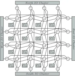
The Kalray mppa R-256 (Bostan version) integrates 288
cores distributed over 16 Compute Clusters and 4 I/O clus-ters interconnected by a dual Network on Chip (or NoC ), as shown in Figure 2. The 16 compute clusters are dedicated to run user applications while the I/O clusters serve as in-terfaces with the out-chip components such as the DDR-SDRAM. All cores are identical 32-bits VLIW processors integrating complex components such as a private MMU (Memory Management Unit) enabling both virtual address-ing and memory protection.
2.1.2
Compute and I/O Clusters
Each compute cluster is composed of 16 cores (named PEs), 1 specific core used for resource management (RM ), 2MiB of Static Random Access Memory (or SRAM) exclu-sively accessible by the elements of the cluster and 1 DMA engine to transfer data between clusters over the NoC. The local SRAM is organised in 16 memory banks that can be accessed in parallel without inter-core interferences.
Each I/O cluster integrates 4 RMs, 4 DMAs (capable of sending data through 4 different NoC access points) and several additional peripherals such as a DDR-SDRAM con-troller or an Ethernet concon-troller.
South IO Cluster North IO Cluster West IO Cl u ster East IO C lus ter C0 C1 C2 C3 C4 C5 C6 C7 C8 C9 C10 C11 C12 C13 C14 C15 R0 R1 R2 R3 R4 R5 R6 R7 R8 R9 R10 R11 R12 R13 R14 R15 Rn0 Rn1 Rn2 Rn3 Rs0 Rs1 Rs2 Rs3 Rw0 Rw1 Rw2 Rw3 Re0 Re1 Re2 Re3
Figure 2: mppa R-256 architecture overview
2.1.3
Network on Chip
Two 2-D torus NoCs interconnect the compute and I/O clusters. The D-NoC can be used for large data transfers while the C-NoC enables inter-cluster barriers thanks to short control messages. In both cases, the route of each packet must be defined explicitly by software.
2.2
Execution model
In [19], we have defined a four-rules execution model in order to ensure a strict temporal isolation between applica-tions. The application designers must follow those rules to avoid any unpredictable or non-segregated behaviours. We give a brief reminder of the four rules of the execution model: Rule 1: Spatial partitioning inside compute clusters Any PE (resp. any local SRAM bank) inside any com-pute cluster can be reserved by at most 1 partition. This rule ensures that a partition will never suffer from local interferences caused by other partitions.
Rule 2: Isolated accesses on the NoC Any communica-tion on a route on the NoC does not encounter any conflict. Given two communications, either they take two non-overlapping routes or they access at different times their overlapping routes. More precisely, com-munications are scheduled in a TDM (Time-Division Multiplexing) manner and strictly periodic slots are defined off-line for each communication.
Rule 3: Off-line pre-defined static buffers The mem-ory areas to be sent over the NoC must be defined off-line. This allows to both reduce the combinatorial explosion of WCET estimation through static analysis and ease the measurement-based validations.
Rule 4: Isolated accesses to DDR-SDRAM bank Any bank of the external DDR-SDRAM memory can be shared by two or more partitions as long as they never access it simultaneously. This allows to greatly miti-gate the inter-partitions interferences at the external bank level.
Some of the rules are enforced by an off-line mapping and computation; while others are ensured by a bare-metal hy-pervisor that we developed. Further low-level details on the implementation of this hypervisor are provided in [19].
2.3
Application model
An application is a tuple hτ, δi where:
1. τ = {τ1, . . . , τn} is a finite set of periodic tasks. A task τiis defined as τi= hSi, Pi, Tii:
• Si = {τi1, . . . , τ ni
i } is the set of sub-tasks in τi with ni the number of sub-tasks composing τi. All the sub-tasks in Si are assumed to be acti-vated simultaneously at the activation of τi and to have the same implicit deadline equal to Ti. Additionally, the sub-tasks are defined as τij = hCij, M j i, I j i, O j ii with: C j
i the WCET of the sub-task; Mij the memory footprint of the sub-task (size of code, static and read-only data); Iij and Oijrespectively the input and output buffers
1read and written by τj
i
• Pi⊂ Si×Siis the finite set of precedence relations constraining the sub-tasks of τi. More precisely, (τx i, τ y i) ∈ Pi means that τ x i must be completed before τiycan start. This kind of precedence rela-tions are assumed to exist only between sub-jobs exchanging some data. Moreover, the precedence constraints imposed by Pihave no cycles and can be seen as a Directed Acyclic Graph (or DAG). • Tithe period of the task.
2. δ = {δ1, . . . , δm} the set of data with δk= hmk, prod, consi with mkthe size of the data; prod : δ 7→ S which pro-vides the sub-job producing the data (with S =SiSi); and cons : δ 7→ Snwhich provides the set of sub-tasks consuming the data.
The model does not allow precedence constraints between sub-tasks having different parent tasks. However, no such constraints are imposed for the data exchanges. The only constraint for data is to be consumed over the freshest-value semantics in a deterministic manner2.
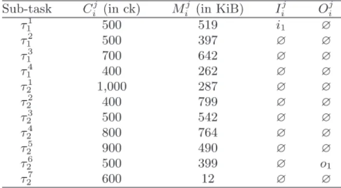
Example 1. We consider an application composed of 2 tasks τ1 and τ2 respectively having 4 and 7 tasks. The 11 sub-tasks exchange 15 data {δa, . . . , δo} and read from 1 input buffer i1 and write into 1 output buffer o1. Tasks τ1 and τ2 respectively have periods T1 = 24 and T2 = 48. The precedence constraints are depicted in Fig. 3a as two DAG (one for each task) and the production and consumption of data by tasks and the I/O buffers are depicted in the form of a multi-digraph in Fig. 3b. The parameters of the sub-tasks are provided in Table 1 (where ck stands for clock cycle). 1The I/O buffers only represent the interactions with out-of-chip components such as the reception or emission of Eth-ernet frames.
2Here deterministic refers to the data production and con-sumption ordering. We consider that two executions of the same schedule must always ensure the same order of pro-duction and consumption of all data.
Sub-task Cj i (in ck) M j i (in KiB) I j i O j i τ1 1 500 519 i1 ∅ τ12 500 397 ∅ ∅ τ3 1 700 642 ∅ ∅ τ4 1 400 262 ∅ ∅ τ1 2 1,000 287 ∅ ∅ τ22 400 799 ∅ ∅ τ3 2 500 542 ∅ ∅ τ4 2 800 764 ∅ ∅ τ25 900 490 ∅ ∅ τ26 500 399 ∅ o1 τ7 2 600 12 ∅ ∅
Table 1: Example of sub-tasks parameters
τ1 1 τ2 1 τ13 τ4 1 τ1 τ21 τ2 2 τ23 τ4 2 τ25 τ6 2 τ7 2 τ2
(a) Precedence constraints
τ1 1 τ2 1 τ3 1 τ4 1 τ1 2 τ2 2 τ3 2 τ4 2 τ 5 2 τ6 2 τ7 2 i1 o1 δa δb δa δb δb δc δe δd δd δd δf δg δg δh δh δi δj δj δk δl δl δm δn δo (b) Data exchanges
Figure 3: Example of sub-tasks dependencies.
2.4
Definition of application’s budget
In [19], we have defined the notion of application bud-get, that is the interface between application designers and the integrator. The application designer must detail to the integrator the amount of resources needed by its software. We remind those definitions below for the paper to be self-contained.
Definition 1. An application budget is defined as a tuple hP, B, I, Ci where
1. P = {P N1, . . . , P Nm} is a finite set of PNs. A Par-tition Node (or PN) is a pair hNc, Nbi which repre-sents the need of processing resource (Nc is a number of cores) and memory (Nbis a number of local memory banks) allocated to an application inside one cluster; 2. B represents a number of external DDRx-SDRAM banks; 3. I = {I/ON1, . . . , I/ONj} is a finite set of I/ONs. An
I/O Node (or I/ON) represents an access point to the external memory. It is materialized as a processor lo-cated on an I/O cluster.
4. C = {P C1, . . . , P Cp} is a finite set of PCs. A Par-tition Communication (or PC) represents a need of communication between two PNs located on two differ-ent clusters (or a PN and an I/ON ) in the form of a directed strictly periodic NoC access slot. Moreover, a PC is defined as a tuple hsrc, dst, hT, C, Oii where:
• src ∈ P ∪ I (resp. dst ∈ P ∪ I) is the source (destination) of the communication. We assume that there exists at most one PC linking src and dst (no two different ways to communicate).
• hT, C, Oi is the strictly periodic slot with period T , duration C and offset O.
3.
BUDGETING
The budget of an application is a set of PNs storing and executing all the tasks, a number of DDR banks, a set of I/ONs, a set of PCs interconnecting the PNs and I/ONs.
3.1
Assumptions
3.1.1
No code fetch
On the Kalray mppa R-256, the PEs cannot directly
ac-cess the external DDR-SDRAM, they must always use the DMA engines instead. In particular, the process of loading code from the external DDR-SDRAM (in case an application does not fit into the local SRAM) must be achieved explic-itly by software. However, we will assume in the rest of the paper that no code fetch from the external DDR-SDRAM ever occurs. Several works already considered code fetch-ing such as [3, 12], we prefer to focus on the multi-cluster parallelization and the efficient use of the NoC instead.
3.1.2
Execution model and hypervisor
One local SRAM bank is reserved by the hypervisor in each cluster (see [19] for further details). Any of the 15 remaining local memory banks can be used by applications. A global tick (denoted as the Systick ) of period Tsys acti-vates periodically the hypervisors of all clusters simultane-ously. Thus, the duration and the period of any PC must be multiple of the Systick.
3.1.3
Valid budget
A budget is valid if the application can execute safely with the resources offered by the budget. More precisely, Definition 2 (Valid budget). For an application A = hτ, δi, a budget hP, B, I, Ci is valid if there exist:
• a mapping of all sub-tasks τj
i ∈ S to P. More pre-cisely, each sub-task is associated to a PN= hNc, Nbi, executes on one of the Nc core and its memory foot-print is stored in the Nb banks;
• a local schedule on each core so that the sub-tasks re-spect their deadlines and their precedence constraints; • a mapping of each sub-task’s I/O to the B DDR banks; • a mapping for each data on a PC from the producer’s
PN to the consumers PNs.
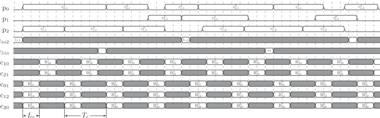
Example 2 (Valid budget and associated schedule). We consider the task set defined in Example 1. As shown on Fig. 4, a valid budget for this task set is composed of three PNs p0, p1and p2; five PCs c10, c21, c01, c12and c20linking the PNs where cij is the PC going from pi to pj, and one I/ON accessible from two PCs cio2and c1io. All PNs have a similar configuration with Nc= 1 and Nb= 15. All the PCs linking the PNs also have an identical configuration with the same duration Lc and the same period Tc. The PCs giving access to the I/ON have a two time longer period.
3.2
Minimal budget
In our approach, the definition of the application’s budget is left to the application designer and can be chosen for any arbitrary reason. To help the user in its budget estimation, we list below several necessary conditions that any budget should meet to have a chance of being valid.
3.2.1
Memory limitations
Since we do not accept any code fetching, the application code and data must be statically allocated in the PNs lo-cal memory. Thus, we can deduce a lower bound on the number of PNs (that is |P|) required to completely store an application. Assuming that the maximum available memory space in each compute cluster is Ma, the number of PNs is bounded by: |P| ≥ P ∀τij∈S Mij Ma
3.2.2
Processing power limitations
An other bound on P can be deduced from the utilization ratio of the application defined as:
U = X ∀τij∈S
Cij Ti
Since the number of cores on which the application is sched-uled must be greater than U , we can deduce:
X pn∈P
Nc(pn) ≥ ⌈U ⌉
On the Kalray mppa R-256, 1 ≤ Nc ≤ 16 for all PNs
because there are 16 PEs in each cluster. Thus, the absolute minimal number of PNs required is ⌈U/16⌉.
Example 3. The memory footprints of the tasks defined in Example 1 are provided in Table 1. We assume the mem-ory space reserved for storing the data to be exchanged to weight Md = 15 KiB. So, the maximum amount of mem-ory available for storing the tasks in each cluster is Ma = 15 ∗ 128 − Md= 1905KiB (16 banks, 1 reserved for the hy-pervisor, 128KiB in each bank). So, we can deduce from the memory limtation that |P| ≥3. The utilization ratio of the task set of Example 1 is 1.85. From the processing power limitation we can deduce:
X pn∈P
Nc(pn) ≥ 2 .
4.
BUDGET VALIDATION
Given a budget, we propose to evaluate its validity by finding a valid schedule of the considered application in the budget with a constraint programming-approach. Such a solution is quite standard to compute off-line mapping and schedule. It also allows to take into account other con-straints coming from the specificities of a many-core plat-form (i.e. the local SRAM limitations or the non-negligible NoC-related delays) and the limitations imposed by the ex-ecution model (i.e. only strictly periodic communications
p0 τ1 2,1 τ2,13 τ1,14 τ2,15 τ2,17 τ1,24 p1 τ2 2,1 τ2,14 τ2,16 p2 τ1 1,1 τ1,13 τ1,12 τ1,21 τ31,2 τ1,22 cio2 i1,1 i1,2 c1io o1 c10 B1 10 B210 B310 B410 B510 B610 B710 B810 c21 B1 21 B221 B321 B421 B521 B621 B721 B821 c01 B1 01 B201 B301 B401 B015 B601 B701 B801 B901 c12 B1 12 B212 B312 B412 B125 B612 B712 B812 B912 c20 B1 20 B220 B320 B420 B205 B620 B720 B820 B920 Tc Lc
Figure 4: Schedule of the application given in example 1 on the budget of example 2. The communication slots used: B2 20= {δb,1}; B4
20= {δd,1, δe,1}; B720= {δb,2}; B208 = {δd,2, δe,2}; B214 = {δd,1}; B218 = {δd,2}; B013 = {δg,1, δh,1}; B017 = {δm,1, δn,1}; B5
10= {δi,1}; B106 = {δj,1}; B712= {δl,1}.
between clusters). To the best of our knowledge, there is no scheduling technique able of managing all those constraints simultaneously in the literature.
4.1
Modelling framework
Many approaches in the literature have been proposed to map dependent task sets on multi/many-core architectures using an ILP formulation of the problem [3,11,20]. However, those approaches often face major scalability issues when applied to large applications making them unusable in an industrial context without considering sub-optimal heuris-tics. In this paper, we use a different modelling framework that has proven to be practically useful in order to overcome the same scalability issues that we faced when we devel-oped the preliminary ILP-based formulation of our indus-trial case study. In the following sections, we will formu-late the scheduling problem using the notion of Conditional Time-Intervals that has been introduced into IBM ILOG CP Optimizer since version 2.0. In order to ease the read-ing, we provide a short introduction to some of the concepts associated with this scheduling framework. Further motiva-tion behind this approach and the formal semantics of the operations on Interval variables can be found in [15] and [16]. An interval variable i represents an activity of finite du-ration l(i) whose start date s(i) must be computed by the solver. Each interval i is defined in a pre-definite time win-dow [a(i), e(i)] where a(i) and e(i) respectively are the ac-tivation and the deadline of i. This means that a correct schedule must always ensure that s(i) ≥ a(i) and s(i)+l(i) ≤ e(i). i is said to be optional if its presence in the final solu-tion is not mandatory. Among all the interval-related con-straints implemented within IBM ILOG CP Optimizer, we use:
• start constraints: the start date s(i) of the interval i can be constrained;
• presence constraints: for an optional interval i, p(i) ∈ [0, 1] denotes whether 1) i is present (i.e. p(i) = 1), in which case i is part of the final solution and all constraints on it must be met, or 2) absent (i.e. p(i) = 0) meaning that i is ignored and not considered in any constraint in which it was originally involved;
• precedence constraints: an interval i1can occur before a second interval i2:
i1→ i2⇔ s(i1) + l(i1) ≤ s(i2)
• alternative constraints: for a set of optional intervals I = {i1, . . . , in}, it is possible to express that only one interval is present and all the others are absent:
⊕(I) ⇔X i∈I
p(i) = 1
• cumulative function constraints: A cumulative func-tion represents the usage of a resource by different ac-tivities over time as the sum of the individual contri-bution of these activities. Cumulative functions can be used to constrain the usage of a resource to fit into a specific envelope representing the resource capabili-ties. Especially, the pulse function ⊓(i, h) increments the usage of resource by h at the beginning of an in-terval i and decrements it at the end of i if i is present. Example 4 (Avoid overlapping with cumulative func-tions). Assuming a set of intervals to be scheduled I = {i1, . . . , in} that all use a single resource that is accessible by only one activity at a time, we can enforce a non-overlapping constraints between these intervals by using cumulative func-tions with P
i∈I
⊓ (i, 1) ≤ 1.
Overall, this formulation with conditional intervals allows a natural modelling of problems in which the activities to be scheduled can be processed by different resources. In such problems, each activity can be associated with several optional intervals (one for each resource) and constrained so that only one of the intervals is present for each activity in the final solution.
4.2
Problem Formulation
4.2.1
Problem inputs
We consider an application A = hτ, δi, a budget hP, B, I, Ci and a specific platform. Since Conditional Time-Intervals apply on jobs and since tasks can have different periods, we
flatten the tasks as jobs on the hyperperiod and the schedule will follow a repeating pattern:
TH= lcm τi∈τ
(Ti)
We define the job τi,k of task τias the k-th activation of τi in one hyperperiod and τi,kj as the k-th activation of the sub-task τij. By doing so, we transform the initial multi-periodic problem into a job scheduling problem. S will represent the set of sub-jobs.
The precedence constraints are assumed to exist only be-tween sub-tasks of the same parent task. Therefore, we du-plicate each constraint on sub-tasks to many constraints on sub-jobs.
Since each data can have at most one producing sub-task, it is assumed to be over-written by each job of this sub-task. When the data must be read by a sub-task allocated to a different cluster, it is sent from the producing cluster to the consuming cluster during a communication slice following its production. The k-th data δx produced by τi,kj is denoted as δx,k.
4.2.2
Decision variables
There are two decision variables:
j: Each sub-job τi,kj ∈ S is associated with |P| optional inter-val variables. ∀pn ∈ P, τi,kj ∈ S, j(τ
j
i,k, pn) is present if τj
i,k is allocated on the PN pn. All the sub-jobs intervals have a fixed length equal to the WCET of the sub-job and are defined in a fixed time window [(k − 1) × Ti; k × Ti].
d: Each data δx,k is associated with |C| optional interval variables. ∀pc ∈ C, δx,k∈ δ, d(δx,k, pc) is present if the data δx,k is sent over the PC pc. The duration of each data interval is fixed and equal to the duration of its corresponding PC. The time window in which a data interval is defined is equal to the one of its producing sub-job.
Remark 1 (Duration of data intervals). Note that the duration of data intervals does not represent the actual time required to send the data over the NoC. The link be-tween the communication time and the number of data allo-cated to the same PC is made in section 4.2.7. Note more-over that during a hyperperiod, there may be several slots for a specific PC (exactly ⌈TH/T ⌉). Thus the start time of an interval d indicates in which slot the data is sent.
4.2.3
PN utilization constraints
Each sub-job is executed only once in only one PN. ∀τi,kj ∈ S, ⊕({j(τ
j
i,k, pn) | ∀pn ∈ P}) (1) If different sub-jobs of the same sub-task could execute on different clusters, it would imply 1) to duplicate the sub-task’s code and data on all of these clusters; 2) to enforce coherency between the static data of all duplicates thanks to NoC communications. So, in order to reduce the pressure on the NoC, the local SRAM and for simplicity reasons, we impose that all sub-jobs of a sub-task execute on the same PN: ∀τi,kj ∈ S, ∀pn ∈ P, p(j(τ j i,k, pn)) = p(j(τ j i,k+1, pn)) (2)
The sub-jobs assigned to a common PN may not overlap. This can be modelled with the utilization using cumulative functions to be less than the number of core Nc:
∀pn ∈ P, X ∀τi,kj ∈S
⊓ (j(τj
i,k, pn), 1) ≤ Nc(pn) (3)
The constraint 3 is a necessary and sufficient condition for being able to execute all sub-tasks allocated to a PN non-preemptively on Nc(pn) cores since the Interval Graph asso-ciated to each PN is chordal and can thus be colored using Nc(pn) colors [9].
4.2.4
Local memory constraints
Each sub-task τij has a memory footprint M j
i that repre-sents the amount of local SRAM used by τij in the cluster to which it is attached. Then, we ensure that the local memory available in each PN Mais sufficient to store the sub-tasks mapped on this PN: ∀pn ∈ P, X τij∈S p(j(τj i,0, pn)) × M j i ≤ Ma (4)
4.2.5
Precedence constraints
The precedence constraints imposed by the application model can be separated in two categories. A precedence constraint (τij, τ
l
i) is said to have:
• forward data ⇔ ∃δx ∈ δ, (τij = prod(δx)) ∧ (τ l i ∈ cons(δx)), • backward data ⇔ ∃δx ∈ δ, (τj i ∈ cons(δx)) ∧ (τ l i = prod(δx)).
With forward data, the freshest value semantics imposes that τl
i cannot start before it receives the data produced by τj
i. If both sub-tasks are executed on the same cluster, the data produced by τj
i will be visible to τ l
i immediately after its production since the address space is shared. In this case, the precedence constraint can be met simply by starting τl i after the completion of τij:
∀(τi,kj , τ l
i,k) ∈ Pi,k, ∀pn ∈ P, j(τi,kj , pn) → j(τ l
i,k, pn) (5) However, if the two sub-tasks are not executed on the same cluster, the data will need to be sent through the NoC after its production to become visible by τl
i. Thus, first, the data must be assigned to a PC slot after the end of the producing sub-job:
∀pc ∈ C, ∀δx,k∈ δ, j(prod(δx,k), src(pc)) → d(δx,k, pc) (6) And then the consumer τl
i cannot start before the com-pletion of the communication slot during which the data is sent: ∀(τi,kj , τ l i,k) ∈ Pi,k, ∀pc ∈ C, ∀δx,k∈ δ, (τj i,k= prod(δx,k)) ∧ (τ l i,k∈ cons(δx,k)) =⇒ d(δx,k, pc) → j(τi,k, dst(pc))l (7) With backward data, the precedence constraint imposes that the data consumed by τi,kj is always the one that was produced by τl
i,k−1. To enforce the respect of this constraint, if the two sub-tasks are on the same cluster we reuse the con-straint 6, otherwise we impose that τi,kj completes before the beginning of the communication slice during which the data
produced by τl
i,k is sent, so that τi,kj could never consume a too fresh data:
∀(τi,kj , τ l i,k) ∈ Pi,k, ∀pc ∈ C, ∀δx,k∈ δ, (τi,kj ∈ cons(δx,k)) ∧ (τ l i,k= prod(δx,k)) =⇒ j(τi,kj , dst(pc)) → d(δx,k, pc) (8)
4.2.6
Data mapping constraints
Any data produced by a sub-job and consumed by any other sub-job hosted on a different cluster is sent during a communication slice after the completion of the producing sub-job. To do so, we constrain the data produced by the first sub-job of a sub-task to be present on a PC if at least one consuming sub-task is present on the destination PN:
∀pc ∈ C, ∀δx∈ δ, p(j(prod(δx,0), src(pc))) ∧ P τi,0j ∈cons(δx,0) p(j(τi,0j , dst(pc))) ≥ 1 ! = p(δx,0, pc) (9)
Additionally, we impose to all sub-data to be placed on the same PC:
∀pc ∈ C, ∀δx,k∈ δ, p(d(δx,k, pc)) = p(d(δx,k+1, pc)) (10) And finally, we enforce all the data sent to be aligned in time with the activation of their PC assuming that T (pc) and O(pc) respectively are the period and the offset of the PC.
∀pc ∈ C, ∀δx,k∈ δ, s(d(δx,k, pc)) mod T (pc) = O(pc) (11)
4.2.7
PC utilization constraints
The amount of data sent during each communication slice must be restricted in order to be compatible with the hard-ware capabilities and to be implementable on the real target. Since our execution model and hypervisor provide a prop-erty of interference avoidance on the NoC [19], we can derive the maximum number of flit that can be sent during one communication slice simply by assuming that the latency of a NoC link is ∆L, that the latency of one router is ∆R and that the maximum number of routers on a NoC route is nmax
R . Indeed, based on the models we introduced in [18], we can deduce that the maximum time required for Nf litto completely cross a NoC route is (nmax
R + 1)∆L+ nmaxR ∆R+ Nf lit. So, we can formulate the maximum number of flits that can be transferred during one communication slice of length Lcas:
NLc
f lit= Lc− (n max
R + 1) × ∆L− nmaxR × ∆R Secondly, in order to compute the number of flits required to send a data δx, we define nδx
bytes and n f lit
bytes respectively as the number of bytes in δxand the number of bytes in one NoC flit. So, the number of payload flits required to transfer the data is nδx f lit = l nδx bytes/n f lit bytes m . Assuming npktf lit to be the maximum number of payload flits in one NoC packet, we can derive the number of packets required to send δxas nδx pkt= l nδx f lit/n pkt f lit m
. Then, with nhead
f lit the number of flits in one NoC packet header and nbbl
cyclesthe number of empty flits lost in the bubble separating two consecutive packets, we can derive the total number of flits Nδx
f litrequired to send
δxas: Nδx f lit= n δx f lit+ n δx pkt× n head f lit + (n δx pkt− 1) × n bbl f lit Finally, in order to simplify the upper-bounding of the amount of data that can be sent during one communica-tion slice, we take the conservative assumpcommunica-tion that all data are placed into non-contiguous memory areas. So, assuming that Nf litgap is the number of empty flits lost in the gap in-curred when the DMA jumps to a non contiguous memory address, we can constrain the amount of data sent into a single communication slice with constraint 12.
∀pc ∈ C, P δx∈δ⊓(d(δx, pc), N δx f lit+ N gap f lit) ≤ N Lc f lit (12) Remark 2 (NoC-aware optimization of the memory mapping). It would be preferable, in order to achieve the best performance, to include the positioning of data with respect to each other into the scheduling problem. Indeed, an optimized memory mapping could enable to group several data into bigger memory chunks that could be sent over the NoC more efficiently. However, such an approach would greatly increase the complexity of the scheduling problem. We will investigate the possibilities of optimal, or at least heuristic, NoC-aware optimization of the memory mapping in future work.
In order to fulfill implementability constraints, we must also take into account the fact that our DMA micro-code is able of autonomously sending only a finite number of non-contiguous memory areas denoted NDM A
buf s . ∀pc ∈ C, X δx∈δ ⊓(d(δx, pc), 1) ≤ NDM A buf s (13)
4.2.8
Determinism constraints
Two sub-jobs are allowed to exchange data without being constrained by a precedence relation. In this case, if a data is produced or received during the execution of a consuming sub-job, the order of consumption of this data could be non-deterministic and even change over time depending on the real execution times of sub-jobs. In this paper, we consider this non-determinism in the data production-consumption ordering as not acceptable since the semantics of such an execution is not clear and would break the repeatability of executions (even with the same set of input values) that is required for test purposes. We avoid this non-determinism by forbidding the overlapping between the data interval and its consuming sub-jobs.
∀δx,k∈ δ, ∀τi,lj ∈ cons(δx,k), ∀pc ∈ C (prod(δx,k), τj i,l) /∈ Pk∧ (τ j i,l, prod(δx,k)) /∈ Pk ⇒ ⊓(d(δx,k, pc), 1) + ⊓(j(τi,lj , dst(pc)), 1) ≤ 1 (14) Similarly, if the producing and the consuming sub-jobs are present on the same PN, they must not overlap:
∀δx,k∈ δ, ∀τj i,l∈ cons(δx,k), ∀pn ∈ P (prod(δx,k), τi,lj) /∈ Pk∧ (τ j i,l, prod(δx,k)) /∈ Pk ⇒ ⊓(j(prod(δx,k), pn), 1) + ⊓(j(τj i,l, pn), 1) ≤ 1 (15)
4.2.9
Managing IOs
In our approach, the communication with out-of-chip com-ponents are handled as read and write requests into the ex-ternal DDR-SDRAM. Indeed, this can simulate the recep-tion and emission of AFDX frames for example.
Since, all transactions with the external memory are han-dled by the compute clusters’ DMAs on the Kalray mppa R
-256, they can be taken into account exactly like the appli-cation’s data. Thus, we assume all the IO buffers to be represented as conditional intervals together with the data. The only difference resides on the PCs on which IO intervals can be placed which are the PCs linking the PNs and the I/ONs. By doing so, all the constraints for data intervals on PCs can be applied directly for managing the IO intervals. In future work, we will integrate the fine grained modelling of the DDR access time that we developed in [18] to the formulation of constraint 12 when applied on PCs targeting I/ONs.
5.
EXPERIMENTAL RESULTS
As a case study, we used a large industrial application from Airbus. This application has several tasks with har-monic periods. The total number of sub-jobs and associated data is close to 100,000 leading to a large optimization prob-lem with several million decision variables and constraints.
5.1
Implementation choices
5.1.1
One PE per PN
In our experiments, we limited the number of cores in each PN to 1 for the following reasons: 1) we limit the po-tential interferences suffered by the computing core to the local memory accesses generated by the DMA in order to simplify and improve the computation of tight WCETs of sub-tasks; 2) we focus on the mostly unexplored 3problem of inter-cluster parallelization requiring a tight management of the NoC to exhibit the application’s speed-up opportuni-ties through parallelization despite the non-negligible NoC-related delays.
5.1.2
Prompt and symmetric PCs
In the budgets considered during the experiments, we al-ways assume symmetric and prompt PCs connecting all the PNs of the budget. By symmetric, we mean that each PN has one outgoing PC to send data to any other PN and all PCs have the same duration Lc and the same period Tc. By prompt, we mean that the value of Lctypically is in the order of magnitude of the Systick and that Tc equal to its minimal value of (n − 1) × Lcwith n the number of PNs.
The symmetry between the PCs is chosen to simplify the expression of the budget and we argue that the promptness of the PCs is well suited for the targeted case study. Indeed, our industrial application basically has many data of small size. By choosing fast PCs we hope to shorten the delays involved by precedences with forward data. The evaluation of fundamentally different budgets with asymmetric and/or slow PCs will be done in future work.
5.2
Goal
Overall, the goal of these experiments is twofold. Firstly, we aim at finding a valid budget with a minimal footprint in order to both maximize the space left to other potential co-running applications and increase the utilization ratio of 3The problem of intra-cluster parallelization has already been addressed in the literature in [3] and the Capacites project [2] and will be further explored in the Assume project [1].
the reserved resources. And secondly, we want to explore the possibilities of speeding-up the application when parallelized over several clusters despite the non negligible latencies in-volved by the NoC.
5.2.1
Narrowing the budget
To minimize the footprint of the budget, we compute a minimal number of PNs denoted as nmin
pn using the rules of Section 3.2. Based on this, we define and evaluate 3 poten-tial configurations with |P| equal to nmin
pn + i for i ∈ [0; 2]. Secondly, we investigate the impact of the NoC config-uration with 3 PC setups where the length of each PC is equal to Lmin
c + j × Systick with j ∈ [0; 2] being the PC configuration number.
5.2.2
Increasing speed-up
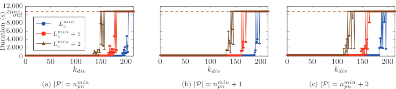
To evaluate the speed-up possibilities, we artificially re-duce the temporal horizon (i.e. the hyperperiod) on which tasks are scheduled. In this case, the maximum speedup and minimal makespan is obtained when no valid budget can be found for any further reduced temporal horizon. We define a division parameter kdivto compute schedules with reduced periods defined as eTi= 256−kdiv
256 × Tiand we evalu-ate 256 instances of the application for 0 ≤ kdiv≤ 255. All other parameters, including the WCETs of sub-tasks are left unchanged.
5.3
Results
Figure 5 shows the time (in seconds) required by the solver to compute a schedule meeting all the constraints as a func-tion of the kdiv parameter in 9 different budget configura-tions. We can see in figure 5a that the maximum kdiv (repre-senting the maximum processing load) is counter-intuitively achieved with the budget configuration offering the smallest number of PNs. However, we can also observe on all three figures that the maximum kdiv are invariably obtained with the shortest PCs. This seems to demonstrate that the bot-tlenecking parameter to achieve the best performance with this case study is the latency of data exchanged through the NoC and not the processing power. The figure 6 depicts an example of PC utilization from the experiment with the maximum kdiv over a complete hyperperiod. The figure 6a shows the number on non contiguous memory areas that are sent during each PC activation and the figure 6b shows the number of flits that are sent in each PC slot. Both fig-ures are annotated with the maximum values imposed by the constraints 13 and 12. We observe that the limitation from constraint 13 (fig. 6a) seems to be a lot more bottle-necking than the limitation from constraint 12. This means that the limiting parameter in this case study is not the ac-tual NoC bandwidth but rather the capabilities of DMAs to send many small non-contiguous data. As mentioned in Remark 2, a better optimized memory mapping could prob-ably help send bigger chunks of data and thus balance the curves of figure 6 to achieve the best performances.
6.
RELATED WORK
In this paper, we presented a mapping procedure enabling the efficient parallelization of one application into its budget. However, since our execution model allows the concurrent execution of several partitions, our mapping technique can be re-used on several applications needing to be mapped into their corresponding budgets. To the best of our knowledge,
0 50 100 150 200 0 2,000 4,000 6,000 8,000 out time-12,000 kdiv Dur atio n (s) Lminc Lminc + 1 Lminc + 2 (a) |P| = nmin pn 0 50 100 150 200 kdiv (b) |P| = nmin pn + 1 0 50 100 150 200 kdiv (c) |P| = nmin pn + 2 Figure 5: Comparison of computation times in function of the load increase with different budgets.
0 TH 4 TH 2 3TH 4 TH NDM A buf s Communication slice
(a) PC utilization regarding the number of DMA buffers
0 TH 4 TH 2 3TH 4 TH NLc f lit Communication slice
(b) PC utilization regarding the amount of data sent
Figure 6: Example of PC utilization under maximum processing load no other approaches enabling the execution of multiple
par-allelized applications on the Kalray mppa R-256 have been
proposed in the literature yet.
Generic DAG scheduling. The theoretical problem of scheduling real-time DAG parallel tasks has already been ad-dressed in the literature for both mono-core [6] and more re-cently multi-core [17,22,23] processors with (G)EDF. How-ever, the classical DAG model used in these papers does not include information on the tasks’ communication latencies or on memory limitations and are thus not directly applica-ble on the Kalray mppa R-256.
Similarly, the static scheduling of DAG tasks on multipro-cessor systems with a makepan-optimization objective has been widely studied, mostly using heuristics based on list algorithms [14]. Nevertheless, to the best of our knowledge, there are no published algorithm able of managing simulta-neously the precedence constraints together with communi-cation latencies, memory limitations and other constraints coming from an execution model.
Mapping on the Kalray MPPA. The problem of map-ping real-time applications on the Kalray mppa R-256 has
already been addressed several times in the literature [3, 8, 10, 12]. In [3], the authors propose a framework for map-ping automotive applications inside a single compute clus-ter accessing the exclus-ternal DDR-SDRAM but never address the problem of multi-clustered applications. On the other hand, the NoC is taken into account in [8] and [10]. How-ever, in both cases, the guarantees on the NoC are provided with a competition-aware approach based on Network Cal-culus. Our approach relies on the competition-free property of the NoC TDM schedule provided by our execution model. We argue that such an approach enables shorter guaranteed NoC latencies that are better suited to benefit from a multi-cluster parallelization [21].
Mapping on other many-core processors or distributed systems. Puffitsch et al. [20] proposed an execution model
and a framework to map dependent task sets on several multi/many-core architectures. However, the message pass-ing latencies are derived from a measured WCTT which oc-curs in a situation of maximum contention while our ap-proach relies on the contention-avoidance property provided by our execution model. In [4], the authors proposed an effi-cient heuristic to map Synchronous Dataflow models onto a time-triggered architecture but the assumptions on the sys-tem model differ from our approach. Indeed, no support is offered to either account for multi-rate applications or handle constraints coming from an execution model. In [7], Craciunas et al. proposed both a SMT and a MIP formula-tion of a co-scheduling problem handling simultaneously the generation of cores and network schedules. Since the authors assume a TTEthernet network and since other constraints such as the memory limitations are taken into account, the goal of the mapping algorithm is very close to ours. The main differences reside in the system model as they assume preemptive scheduling at the tt-tasks level while we assume non preemptive scheduling at the sub-task level. Moreover, all the tt-tasks are assumed to be pre-assigned to an end-system while our approach includes the placement of sub-tasks to cores together with the core and NoC scheduling.
7.
CONCLUSION
In this paper, we have proposed an approach enabling the automatic parallelization of large applications onto the MPPA architecture. This approach meets the requirements imposed by the execution model providing the property of strong temporal isolation between co-running applications thanks to spatial and temporal partitioning. We provided a formulation of the mapping problem as a CSP using the notion of time-intervals and we demonstrated the ability of the approach to deal with large problems with an indus-trial case study. Overall, the mapping procedure that we described in this paper together with the real world
imple-mentation of our execution model that we presented in [19] form a complete work-flow enabling an end-to-end integra-tion of real-time applicaintegra-tions on the Kalray mppa R-256.
In the future, we will propose additional guidelines to help the application designers in the process of defining their bud-gets and we will investigate the optimization possibilities of the memory mappings in order to improve the NoC utiliza-tion and the overall performances.
8.
REFERENCES
[1] Affordable Safe And Secure Mobility Evolution (ASSUME). http://www.assume-project.eu/. [2] Parallel Computing for Time and Safety Critical
Applications (CAPACITES). http://capacites.minalogic.net/en/.
[3] M. Becker, D. Dasari, B. Nicolic, B. ˚Akesson, V. N´elis, and T. Nolte. Contention-Free Execution of
Automotive Applications on a Clustered Many-Core Platform. In 28th Euromicro Conference on Real-Time Systems (ECRTS’16), July 2016.
[4] T. Carle, M. Djemal, D. Potop-Butucaru, and R. De Simone. Static mapping of real-time
applications onto massively parallel processor arrays. In 14th International Conference on Application of Concurrency to System Design (ACSD’14), pages 112–121, 2014.
[5] CAST (Certification Authorities Software Team). Position Paper on Multi-core Processors - CAST-32, 2014.
[6] H. Chetto, M. Silly, and T. Bouchentouf. Dynamic scheduling of real-time tasks under precedence constraints. Real-Time Systems, 2(3):181–194, 1990. [7] S. S. Craciunas and R. S. Oliver. Combined task- and
network-level scheduling for distributed time-triggered systems. Real-Time Systems, 52(2):161–200, 2016. [8] B. D. de Dinechin, Y. Durand, D. van Amstel, and
A. Ghiti. Guaranteed Services of the NoC of a Manycore Processor. In 2014 International Workshop on Network on Chip Architectures (NoCArc’14), pages 11–16, 2014.
[9] F. Gavril. Algorithms for Minimum Coloring,
Maximum Clique, Minimum Covering by Cliques, and Maximum Independent Set of a Chordal Graph. SIAM Journal on Computing, 1(2):180–187, 1972.
[10] G. Giannopoulou, N. Stoimenov, P. Huang, L. Thiele, and B. D. de Dinechin. Mixed-criticality scheduling on cluster-based manycores with shared communication and storage resources. Real-Time Systems, pages 1–51, 2015.
[11] R. Gorcitz, E. Kofman, T. Carle, D. Potop-Butucaru, and R. De Simone. On the Scalability of Constraint Solving for Static/Off-Line Real-Time Scheduling. In 13th International Conference on Formal Modeling and Analysis of Timed Systems (FORMATS’15), pages 108–123, 2015.
[12] A. Graillat. Code Generation of Time Critical Synchronous Programs on the Kalray MPPA
Many-Core architecture. In 7th Workshop on Analysis Tools and Methodologies for Embedded and Real-Time Systems (WATERS’16), 2016.
[13] X. Jean, L. Mutuel, D. Regis, H. Misson, G. Berthon, and M. Fumey. White Paper on Issues Associated with
Interference Applied to Multicore Processors, 2016. [14] Y.-K. Kwok and I. Ahmad. Static Scheduling
Algorithms for Allocating Directed Task Graphs to Multiprocessors. ACM Comput. Surv., 31(4):406–471, Dec. 1999.
[15] P. Laborie and J. Rogerie. Reasoning with Conditional Time-intervals. In 21st International Florida Artificial Intelligence Research Society Conference
(FLAIRS’08), 2008.
[16] P. Laborie, J. Rogerie, P. Shaw, and P. Vil´ım. Reasoning with Conditional Time-Intervals. Part II: An Algebraical Model for Resources. In 22nd International Florida Artificial Intelligence Research Society Conference (FLAIRS’09), 2009.
[17] J. Li, K. Agrawal, C. Lu, and C. Gill. Analysis of Global EDF for Parallel Tasks . In 25th Euromicro Conference on Real-Time Systems (ECRTS’13), 2013. [18] Q. Perret, P. Maur`ere, ´E. Noulard, C. Pagetti,
P. Sainrat, and B. Triquet. Predictable composition of memory accesses on many-core processors. In 8th Conference on Embedded Real Time Software and Systems (ERTS’16), 2016.
[19] Q. Perret, P. Maur`ere, ´E. Noulard, C. Pagetti, P. Sainrat, and B. Triquet. Temporal isolation of hard real-time applications on many-core processors. In 22nd IEEE Real-Time and Embedded Technology and Applications Symposium (RTAS’16), 2016.
[20] W. Puffitsch, ´E. Noulard, and C. Pagetti. Off-line mapping of multi-rate dependent task sets to many-core platforms. Real-Time Systems, 51(5):526–565, 2015.
[21] W. Puffitsch, R. B. Sørensen, and M. Schoeberl. Time-division Multiplexing vs Network Calculus: A Comparison. In 23rd International Conference on Real Time and Networks Systems (RTNS’15), pages 289–296, 2015.
[22] M. Qamhieh, F. Fauberteau, L. George, and S. Midonnet. Global EDF Scheduling of Directed Acyclic Graphs on Multiprocessor Systems. In 21st International Conference on Real-Time Networks and Systems (RTNS’13), pages 287–296, 2013.
[23] M. Qamhieh, L. George, and S. Midonnet. A Stretching Algorithm for Parallel Real-time DAG Tasks on Multiprocessor Systems. In 22nd
International Conference on Real-Time Networks and Systems (RTNS’14), pages 13–22, Oct. 2014.
[24] Radio Technical Commission for Aeronautics (RTCA) and EURopean Organisation for Civil Aviation Equipment (EUROCAE). DO-297: Software, electronic, integrated modular avionics (ima)
development guidance and certification considerations. [25] Radio Technical Commission for Aeronautics (RTCA)
and EURopean Organisation for Civil Aviation Equipment (EUROCAE). DO-178C: Software considerations in airborne systems and equipment certification, 2011.
[26] R. Wilhelm and J. Reineke. Embedded systems: Many cores - many problems. In 7th IEEE International Symposium on Industrial Embedded Systems (SIES’12), pages 176–180, 2012.