OATAO is an open access repository that collects the work of Toulouse
researchers and makes it freely available over the web where possible
Any correspondence concerning this service should be sent
to the repository administrator:
[email protected]
This is an author’s version published in: http://oatao.univ-toulouse.fr/23403
To cite this version:
Nahed, Rudy
and Dalverny, Olivier
and Chiummo, Antonino
and Ferrato, Marc Study and development of silicon carbide stray
light optical components for third generation gravitational wave
detectors. In: GWADW2016 – Impact of recent discoveries on
future detector design, 22 May 2016 - 28 May 2016 (Isola d'Elba,
Italy). (Unpublished)
Study and Development of Silicon Carbide Stray Light
Optical Components for Third Generation Gravitational
Wave Detectors
R. NAHED
1,2; O. DALVERNY
1; A. CHIUMMO
3; M. FERRATO
2• BOOSTEC® SiC could be a good candidate for baffles for the third generation gravitational wave detectors regarding its thermal and mechanical properties.
• MERSEN SiC-CVD is a very promising material for this purpose due to its agreement with the optical requirements desired.
• Preliminary results of FE modeling interaction between the test mass and the baffle allowing us to study and analyze their temperature variation .
Problematic and research objectives
Conclusion & Next Steps
The chamber and the core optics with stray light
Methodology of simulation
Fig: BOOSTEC® SiC experimental data as a function of the temperature, (a) thermal conductivity, (b) thermal expansion.
[Credits: J.Marque, Lecture at VESF school 2012, EGO, Italy]
#1 Arm-duct baffles #4 Wide angle baffles
#2 Cryo-duct baffles #3 Narrow angle baffles Laser BS
[Akutsu T. and al., Opt Society of America. 2016] [Credits: A. Moggi (INFN-PISA)]
Candidate
Requirements SS 304 Al-NiPW SiC-CVD SiC
Low Scattering •(RT) •• ••• •
High Laser Induced Damage Threshold LIDT ••(RT) ••• •••
High Thermal Conductivity • ••• ••• •••
Low Thermal Expansion •• • ••• •••
High Stifness •• • ••• •••
High Absorption Coefficient • ••• ••• ••
••• Most promising candidate
Physical characterization of BOOSTEC® SiC
(a) (b)
• Material Requirement (SiC is a very promising candidate) • Optical Characterization
• Measuring the scattering at room temperature (Advanced VIRGO) and at cryogenic temperature (Einstein Telescope ET)
• Same conditions for measuring the reflectivity of SiC
Optical Simulation Thermal Simulation Mechanical Simulation Optical properties Mechanical properties Scattering light field Temperature field Thermal BC Laser input Mechanical BC Thermal properties
Polished Sample Process
Surface Roughness (nm) TIS** (ppm) TIS* (ppm) Reflectivity at Brewster angle(%) Reflectivity at 3 deg (%)
HIP BOOSTEC® SiC Hot Isostatic Pressing 5 3487 2120 0.2 21 BOOSTEC® SiC polished (no
HIP) Pressureless sintering 2 558 4360 0.2 19 MERSEN SiC-CVD Chemical Vaper Deposition < 1 <<< 50 0.1 19
[V. Bavigadda, and A. Magazzu, EGO, Cascina (Italy)] [Bennett and Porteus]
Incident beam Radiative Exchange
with surrounding
Thermal flux from scattering light
1Université de Toulouse; INP/ENIT; LGP ; Tarbes – LGP. 47, avenue d’Azereix - BP 1629, 65016 Tarbes Cedex, France 2MERSEN BOOSTEC-zone industrielle-65460-Bazet; France
³ EGO; Advance VIRGO; Cascina (PI), Italy
* E-mail: [email protected]
Optical BC
Problematic
Research objectives
Methodology
Optical Work
Simulation work
• Optical characterization of the most promising materials (SiC, coated SiC…), • Analysis of the thermal and thermomechanical changes induced by scattering light flux, • Analysis of the influence of this changes on the scattering light process (if needed). All the methodology could be applied to advanced virgo and/or third generation interferometer. Key points : cryogenic temperature, high laser power density
Optical characterization of 3 samples of MERSEN SiC
!"#$=%&'(
%)*
• Steady state thermal analysis • Open cavity radiation • View factor interaction
• Radiative interaction with surrounding
• Radiative Interaction between the optical components
• Thermal flux distribution on the baffle obtained from optical simulations
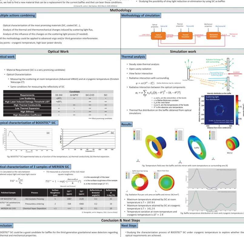
Results
Fig: Temperature field over the baffle and the mirror with room temperature as surrounding one (K) baffle
Mirror
Fig: Baffle temperature distribution at room and cryogenic temperatures (K)
Baffle back face facing the mirror
Mirror front face
Fig: Radiation flux per unit area on baffle and mirror (W/mm²)
u, ε, +
[1] Canuel B., and al., Opt Express. 2013 May 6; 21(9):10546-62
Thermal analysis
, = -./012 0 314
• Studying and analysing the thermal and mechanical behavior of SiC under interferomrter conditions • Studying the possibility of stray light reduction or elimination by using SiC as baffles
Advanced VIRGO core optic chamber system Stray light is the light that does not follow the intended path reaching the detector [1]. Subsequently, stray light was considered as
an issue because scattered light from surfaces other than the mirrors surface, such as the walls of the cavity, will carry information about the displacement of the wall that will recouple back with the main beam adding a stray light field to the unperturbed field inside the interferometer:
5(&(67= 5)*8 53= 5)*8 93:5&'(-);<( 5(&(67= 5)*exp[ 93:
%&'(
%)*
/cos ;3 > 8 ?@?A ;3 > 4]
This final profile of the equation contains a real part and an imaginary part. In this sense, the real part represents the amplitude modulation induced BC (
C and the imaginary part represents the phase modulation A;/>4 [1]:
D% > % = 93: %&'( %)* cos ;3 > A;/>4 = 93: %&'( %)* @?A ;3 >
Where 53is the stray light field, 5&'(is the output field and ;3is the phase angle thet carries information about the scattered light.
Stray light in the current detectors is being reduced using light shades called « baffles ». In fact, the third generation detector will be using a very high power laser and the test masses will be subjected to a different temperature condition « cryogenic temperature ». Hence, we had to find a new material that can be a replacement for the current baffles and thet can bear these conditions.
Mechanical field
• TIS is calculated as the ratio between scattered output light and input light source
• Studying the characterization process of BOOSTEC® SiC under cryogenic temperature to explore whether the optical requirements are achieved.
• FE Studies of the thermal analysis of the conduction process.
• Mechanical analysis under room and cryogenic temperature of SiC setup must be explored to evaluate displacement, stress; strain and analyze mechanical behavior.
• Evaluating the possibility of using different types of coatings with the same substrate SiC.
Conclusion
Next Steps
• Maximum temperature attained by SiC at room temperature is T = 297.8 K
• Maximum temperature attained by SiC at cryogenic temperature is T = 141.2 K
• Temperature variation at room temperature and cryogenic temperature is E! = F G
Multiple actions combining
Optical work
Baffle solutions in KAGRA interferometer
Baffle solutions in Advanced VIRGO
Scattering light flux distribution
[Credits: A. Chiummo and E. Genin, EGO, Cascina, Advanced VIRGO, Italy]
• TIS measured as a function of the root mean square roughness
!"#$$= H 2 exp[2/IJKL@0).
M 4
N]
[Stefan-Boltzman law for radiation]