OATAO is an open access repository that collects the work of Toulouse
researchers and makes it freely available over the web where possible
Any correspondence concerning this service should be sent
to the repository administrator:
[email protected]
This is an author’s version published in:
http://oatao.univ-toulouse.fr/2
2025
To cite this version:
Ober, Ileana and Palyart, Marc and Bruel, Jean-Michel and Lugato, David On the use of models for high-performance scientific computing applications: an experience report. (2018) International Journal on Software and Systems Modeling, 17. 319-342. ISSN 1619-1366.
Official URL:
https://doi.org/10.1007/s10270-016-0518-0
On the use of models for high-performance scientific computing
applications: an experience report
Ileana Ober1 • Marc Palyart2 • Jean-Michel Bruel1 • David Lugato3
Abstract This paper reports on a four-year project that aims to raise the abstraction level through the use of model driven engineering (MDE) techniques in the development of scientific applications relying on high-performance comput ing. The development and maintenance of high-performance scientific computing software is reputedly a complex task. This complexity results from the frequent evolutions of supercomputers and the tight coupling between software and hardware aspects. Moreover, current parallel programming approaches result in a mixing of concems within the source code. Our approach relies on the use of MDE and consists in defining domain-specific modeling languages targeting var ious domain experts involved in the development of HPC applications, allowing each of them to handle their dedicated mode! in a both user-friendly and hardware-independent way. The different concems are separated thanks to the use of several models as well as several modeling viewpoints on these models. Depending on the targeted execution plat forms, these abstract models are translated into executable implementations by means of mode! transformations. To make ail of these effective, we have developed a tool chain Communicated by Prof. Dorina Petriu.
181 Ileana Ober [email protected] 2 Marc Palyart [email protected] Jean-Michel Bruel [email protected] David Lugato [email protected]
IRIT, University of Toulouse, Toulouse, France University of British Columbia, Vancouver, BC, Canada CEA CESTA, Le Barp, France
that is also presented in this paper. The approach is assessed through a multi-dimensional validation that focuses on its applicability, its expressiveness and its efficiency. To cap italize on the gained experience, we analyze some lessons leamed during this project.
Keywords HPC · High-performance calculus · MDE · Model-driven engineering · Architecture · Fortran
1 Introduction
It is not every day that Nature--one of the most influen tial interdisciplinary research joumals-focuses on topics related to computer science. In 2010, a paper dedicated to sci entific computing [40] stressed the bard time scientists have due to the increased importance of software use and devel opment in their work coupled with Jack of formai training to software development. The paper revealed that scientific computer engineers face major problems in effectively main taining scientific software, in a domain where software life spans count in decades, whereas the underlying hardware is highly volatile.
Since the 1960s, the increase in hardware performance has been continuous and followed Moore's law [44]. In this landscape, the last decade brought a major shift in the way hardware performance increases. While we were used ben efiting from faster processor chips thanks to the decrease in transistors size, as we approach the physical limits of minia turization, the increase in performance witnessed over the past IOyears is due to the widespread use of complex parai lei architectures.
This change bas some serious repercussions. Software applications no longer benefit automatically from perfor mance increases. They need to be completely redesigned.
108
-;:,;
106 10• o.. 102 -1-� � -e-1,994 Sum #1 #500 CEA 1,998 2,002 Year lphone 6 2,006 2,010 2,014Fig. 1 Performance development
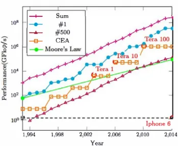
As highlighted in [38], the new performance gains mecha nism "shift[ s] the burden of software performance from chip designers and processor architects to software developers." High-performance computing (HPC) has always been an area where parallel architectures were used to gain more com putational power. Over the last 20 years, the performance of the world's most powerful supercomputers used by the HPC community has been scrutinized by the TOP500 group.1 Figure l , generated via information available on Top500, illustrates that the performance increases in the last years. This chart highlights several interesting facts. First, by fol lowing the topmost curve (cross shaped and labeled Sum), we can see that the cumulative performance of the world's 500 most powerful supercomputers outpaces Moore's law. Moreover, we can see that the evolution is even more vigor ous for the world #1 (dot shaped and labeled #J). This curve shows a more stepwise evolution, where steps correspond to technological breakthroughs that happen regularly and to the fact the top 500 is released twice a year. We must point out that these rapid hardware developments are also driven by energy performance goals. As highlighted in a recent study [55], performance growth shows a recent slowdown in performance increase, which is analyzed as being due to "hardware-, software- and funding-" related causes.
Since the world's most powerful supercomputer changes regularly, one may think that the strong performance increase would not correspond to the reality within the same orga nization. While it is true that the owner of the world's most powerful computer changes frequently, the need for performance increase within an organization is following a sirnilarly strong increase, with all the software porting and maintenance issues that corne with it. In Fig. l , the square shaped curve depicts the performance evolution within CEA, 1 http://www.top500.org.
the French Atornic Energy and Alternative Energies Com mission. As part of its Tera program [24], CEA plans to change its main supercomputer every 4 years. As one can see, this evolution follows the general tendency and outpaces Moore's law. This rapid growth in performance cornes at the expense of inevitable hardware and software technological breakthroughs. 2
1.1 Current practice in HPC application development One of the main concerns of the high-performance scien tific computing developer community is to produce efficient code for numerical simulation. Due to their thirst for com putational power, the shift in the performance increase mechanism that involves the intensive use of parallelization had to be initiated a long rime ago. As often highlighted (e.g., [54]), current mainstream parallel programrning mod els, and in particular those addressing HPC, are low level and machine specific. Even though good performance levels can be achieved with these approaches, drawbacks in terms of architecture dependency, rnix-up of concerns and program rning complexity occur:
- Applications versus supercomputers lifetime cycle. Physics does not change frequently, supercomputers do. In this application domain, the life cycle of supercom puters is sometimes five to seven times shorter than the life cycle of scientific applications. For example, CEA's experience has shown that the simulation models and numerical analysis methods associated with our profes sional problems have a life expectancy of 20-30 years and must therefore be maintained over that period, with all the additional problems that come with software main tenance over such a period of rime (e.g., team turnover). - The lack of separation of concerns. The problem to be solved-the scientific knowledge of the physics is entirely rnixed with numerical schemes and target dependent information, added to manage the parallelism. Once a complex system has been built, it is difficult to extract the physical models. As a result, maintenance and upgrading become even more complicated.
- Inaccessibility to domain experts. The complexity of soft ware programrning restricts the use of these workstations and supercomputers to a few scientists who are willing to spend a significant amount of time learning the character istics of a particular set of machines to take full advantage of their capabilities.
Furthermore, the situation is getting worse with the new emerging generation of machines: hybrid machines. They are 2 It is instructive to note that the Jast iPhone6 could have been ranked in the top 500 in 1994, the reader may find the performance of bis own computer in [21).
built by mixing heterogeneous hardware resources such as CPUs with many cores and graphics processing units. GPUs are usually found within graphics cards, where they com-pute the rendering of massive 2D and 3D scenes. However, hardware manufacturers of supercomputers have started to integrate GPUs, since they are particularly well suited to specific operations such as fast Fourier transform or matrix computations and thus linear algebra solving. GPUs contain a large number (in the range of hundreds) of stream processors which increase the computation power of supercomputers. To exploit them, however, developers have to depend on hardware manufacturer-specific instructions (NVIDIA Cuda [36]), or in the best case, on libraries which attempt to be more generic such as the OpenCL API [34].
Our research goal in this context is to apply model-driven techniques to define a tool-supported approach where the separation of concerns, the domain expert accessibility and reactivity to the hardware evolution would be addressed as primary concerns, not just as extra-functional features as they often are.
1.2 Overview of our approach
Our thesis is that model-driven development techniques can help us deal with the complexity existing in high-performance and scientific computing applications.
We feel that high-performance computing is a typical can-didate for applying model-driven development techniques in order to deal with this complexity and to facilitate porta-bility by using abstraction. This befitting is due to the fact there is a huge need for maintenance in terms of hardware architecture change; thus, techniques that help distinguish between platform-dependent and platform-independent code are much needed. This is precisely a strength of model-driven techniques.
Our approach consists in defining a method and a toolset supporting the use of the abstraction principles specific to model-based software development (MBSD) techniques in the context of HPC applications that use partial-differential equations with mesh-based numerical modeling. In order to assess the feasibility of this approach, we applied it to signifi-cant size HPC applications of realistic algorithm complexity, involving several domain expertises.
In this paper, we detail the following contributions: – MDE4HPC—our approach for adding abstraction in
HPC applications by applying the principles of MBSD.
An earlier presentation of this approach was published previously here [51];
– An abstraction-based hierarchy of a set of
domain-specific languages addressing the needs of various
business domains, with a focus on HPCML—the domain-specific language that we defined as an answer to
the abstraction needs of HPC applications. A partial overview of HPCML is available in a previous paper [52]. The current paper introduces the need for a hierarchy of domain-specific languages and positions HPCML in this hierarchy.
– A toolset-ArchiMDE—allowing the use of our tech-niques in an industrial setting. Our assumption is that we need an integrated tool set offering the functionalities needed by the various business domains (such as physi-cists, applied mathematicians), supporting MDE4HPC and natively using our domain-specific language
HPCML, while offering services such as model
trans-formation, code generation, validation and compiling. Although we partially describe the architecture of this tool set in previous publications [46,50,51], this paper gives a complete overview of our toolset.
– A multi-dimensional validation We have validated the approach by applying it to large HPC applications. Given the variety and complexity of HPC applications, we opted for a three-dimensional validation.
First, we focus on the overall applicability of our method. For this, we used ArchiMDE to model a simpli-fied Lagrangian hydrodynamic module. This case study, also described in [50], shows that it is possible to obtain viable code, in terms of performance, using HPCML and that this decreases the maintenance costs.
The second case study aims at an expressiveness
assessment on the capacity of our domain-specific
lan-guage to model an application under industrial usage, based on a different physical domain. For this, we reverse-engineered a subset of a simulation software used in production for electromagnetism and show that it is pos-sible to model it using our domain-specific language. This case study, essential in our view for a multi-dimensional evaluation, was never published before.
The third validation aims at an efficiency assessment, and it is based on the second case study and consists in analyzing the execution time of the numerical simula-tion of the electromagnetism applicasimula-tion code obtained by using our approach and comparing it with the origi-nal “old-style” code. For this, we have performed several sets of simulations on the Terra100 supercomputer, by varying the number of processors. These results have not been published before.
This multi-dimensional validation shows that introduc-ing abstraction in HPC applications is not incompatible with preserving performance. We consider this as a very important result in a domain culturally dedicated to low-level optimizations and closeness to hardware archi-tecture.
– A set of lessons learned during our four-year experience in applying modeling techniques to high-performance computing. These lessons, which go beyond the context
of HPC, could be useful for further experiences of apply ing MDE to new domains.
The paper is organized as follows. Section 2 presents the main principles of our approach. The domain-specific lan guage that we defined to address the abstraction needs of HPC is introduced in Sect. 3. Section 4 presents the tool chain that supports our approach. The multi-dimensional evaluation that we propose for our approach is detailed in Sect. 5 which also contains a broader discussion. Section
6 describes the tessons learned from this project. Section 7
presents related work on existing solutions for developing numerical simulations with a focus on approaches aiming at adding abstraction. Section 8 discusses the conclusions of our project and areas for future work.
2 MDE4HPC the step toward adding abstraction As highlighted in the previous section, the major goal of our approach consists in increasing the abstraction level throughout the development life cycle of numerical simu lation applications.
The key characteristics of high-performance computing applications are deeply analyzed here [22, 32]. According to [22], the common characteristics of scientific application that makes use of high-performance computing are: (l) the computational performance involved, (2) the target range of platforms-and the changing targets, (3) the number of sep arate disciplines involved in the development teams, (4) the size of software effort to develop and build the needed soft ware, (5) the size of software effort to maintain software and (6) the economical model. Our study explicitly addresses the characteristics (2), (3), (4) and (5) while concerned of the first one (l).
At first sight, the choice of a (subset of) UML could seem like a natural choice of language for our approach: It sup ports abstract reasoning with a good expressiveness and it is a fairly widespread language. However, in the context of sci entific simulation software, the models expose information of various natures (numerical, physical, algorithmic, plat form dependent, etc.) that is exploited by various types of domain experts. For this reason, instead of a large general modeling language, such as UML, we prefer to use a set of focused domain-specific modeling languages (DSML), ide ally accessible to domain experts, as long as there is a set of model transformations to move from one DSML to the other. It soon became obvious that the definition of the DSMLs and transformations would need to go hand in hand with a dedi cated tool suite and a set of methodological guidelines.
In this section, we introduce MDE4HPC, our approach for applying the principles of MBSD on the development of scientific simulation software. In particular, we describe the
Physical Model HPCML Numerical Mode! HPCML0 Execution Mode! HPCML8
Fig. 2 HierarchicaJ abstraction Jayering in MDE4HPC
general structure of the domain-specific modeling language called High-Performance Computer Modeling Language (HPCML) on which the approach is built.
2.1 Overview of the approach
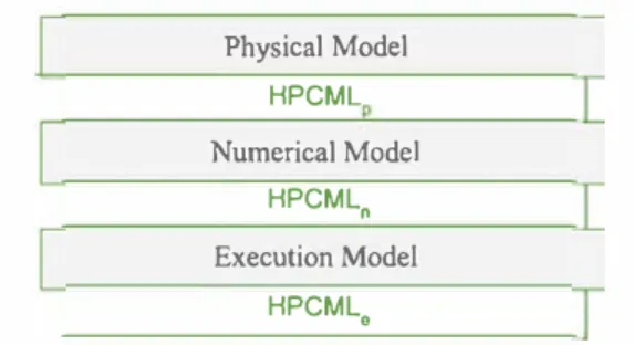
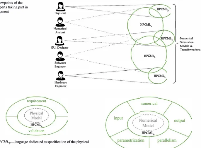
The MDE4HPC approach follows a classical model-based strategy: model all artifacts-including those that are non software- dependent-produced by the range of experts who typically take part in the development (physicists, applied mathematicians, computer scientists, hardware and software architects) and combine them to generate the simulation code. To that end, the MDE4HPC approach offers a multi layered architecture relying on several abstraction levels where each abstraction level targets specific types of experts. Figure 2 depicts an overall view of the hierarchical abstraction layering in MDE4HPC. We find two types of elements in this diagram: models (one type per domain) and HPCML which acts as middleman between the three domains. For these reasons, HPCML is decomposed into three sub-languages: HPCMLp-the layer dedicated to physics, HPCMLn-the layer dedicated to mathematics and HPCMLe-the layer dedicated to execution-related matters (software and hardware). Several types of experts might be found in a given domain. Figure 3 illustrates the situation by showing the different viewpoints on the models of some domain experts and how they overlap. Each ellipse repre sents an abstract view of the model elements used by the corresponding expert as well as which part of the HPCML language they depend on. With this figure, we better under
stand that numerous artifacts are used and required by several domain experts. The HPCML language allows the exis tence of a common underlying model, thus facilitating the exchange of information between various domains. It also enables the traceability of decisions and concepts across the various abstraction levels.
2.2 Physics-dedicated layer
The physicist is usually the person formulating the require ments for a numerical simulation. He is also frequently the
Fig. 3 Viewpoints of the domain experts taking part in
the development Physicist
�
-·- -·-·· -
_ ...-
-.. - - ··- HPCML0 Numerical ··- .•. _ ··- •. AnalystA··""
:
:
:
:
:
::
:
:
:
::
:
:
::
:
:::
:
:
:
:
:
:
:
:
:
::::
:
::
:
:
�
:-
�
-
-�--
�
-
-
:
��
�::�\�
-
-
-�
.
:�.
.
:�
_
...____
___
GUI Designer Numerical Simulation Modcls& Transformations'9
-::::
:::
:·
�
:
�
:�:
�
HPCML• requirement validation Software EnginccrFig. 4 HPCMLp-language dedicated to specification of the physicaJ mode)
final user of the simulation application. In our setting, the lan guage HPCMLp (p stands for Physics) provides primitives to support these two roles. Figure 4 depicts the structure of the HPCMLp language with its two parts:
- requirement the physicist must be able to specify its phys ical mode! (in terms of equations, hypothesis, properties for example), as well as the modeling choices that led to this mode!.
- validation the physicist must be able to specify the valid ity range of its mode! and annotate this range with expected properties of the obtained results.
2.3 Mathematics-dedicated layer
HPCML11 (n stands for Numerical) provides pruruttves required by a numerical analyst to precisely specify the numerical schema picked as a solution for the resolution of the physical mode! defined by a physicist. This part of HPCML;s central to our approach, as it interacts with the two other parts of the language.
The primitives of HPCML11 aim to abstract as much as possible ail the software and hardware concerns related to the
numerical
---
...Fig. 5 HPCMLn-language dedicated to modeling the numerical information
target execution platform for two reasons. First it improves accessibility for the numerical analysts who in general have a limited training in computer science. Second it increases the portability capability of the applications developed using our approach by making them Jess impacted by software and hardware technological breakthroughs. Overall the definition of this part of the language is not straightforward sin ce we aim for a high abstraction level while being concrete enough to be able to specialize the numerical mode! to a concrete execution platform. Figure 5 provides an overview of the structure of the HPCML11 language, whose major components are:
- input-the numerical analyst must be able to specify in an orderly manner input data for its simulation code. These parameters can either be of physical or mathe matical nature. Typically, the information contained in this part of the mode! can be used to generate the graphi cal user interfaces that are used for exploiting simulation code.
- numerical�e numerical analyst must be able to specify her numerical algorithm using a formalism close to math ematics, which is her native domain-specific language.
This part of the language enables inter-application reuse thanks to composition mechanisms.
- parallelism-the numerical analyst expert must be able to specify potential sources of parallelism in her applica tion without having to master advanced concepts specific to a supercomputer.
- output-the numerical analyst must be able to specify the computation results that need to be exported from the application. This part of the language provides vol untarily abstract concepts to facilitate integration with software used post-simulation such as scientific visual ization software.
- parametrization-the numeric analyst must be able to specify how her application can be used for conducting parametric studies. This part of the model can be used to both generate user interfaces for conducting paramet ric studies and exploit the parallelism provided by such parametric studies.
2.4 Execution-dedicated layer
Our approach relies on a clear separation of concems in order to allow each type of domain expert to focus on activities and
optimization
---L
Fig. 6 HPCML,-DSML that targets the software part
Fig. 7 MDE4HPC development process HPCML p <<CIM>>
[Œ) :
Transformation@ :
Modificationinformation specific to their field. Thanks to the abstractions
provided by HPCMLn, several computer-oriented aspects
that in current practice are assigned to numerical analysts can be transferred back to hardware and software engineers.
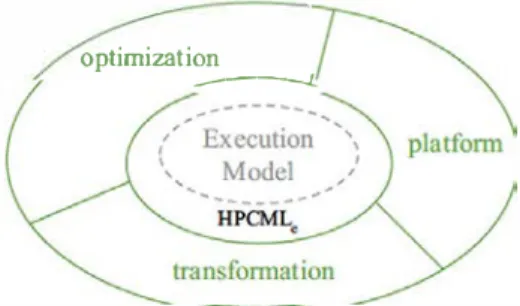
The goal of the HPCMLe (e stands for Execution) is to offer to hardware and software engineers the primitives needed to specify how a numerical resolution model spec ified with HPCMLn should be implemented on a specific target platform. Figure 6 depicts the structure of HPCMLe, mainly focusing on three aspects:
- optimization-the engineer must be able to annotate a numerical model to specify what kind of optimization (improved algorithm, memory management, processor specificity, etc.) he wants to apply during the transforma tion toward a particular execution platform;
- platform-the engineer must be able to describe the exe cution platform. This specification would parametrize the model transformations leading to the simulation code generation;
- transformation---besides generic model transformations shared by several projects, the engineer must be able to define transformations specific to a particular project, either to enable some optimizations or to handle new platform characteristics.
2.5 Development process
The development process promoted by MDE4HPC is pre sented in Fig. 7. We distinguish several models (oval shapes)
based on the three sub-languages of HPCML we introduced
in the previous sections. We notice that the MDE4HPC
process can be mapped to a certain extent to the OMG Model
Driven Architecture recommendations [41]. An HPCMLp
mode) can be viewed as a Computation lndependent Mode!
HPCMLn
<<PIM>>
<<PSM>>
<<PDM>>
(CIM) since it describes the problem. An HPCMLnmodel
can be viewed as a Platform-Independent Model (PIM) since it describes how to solve the problem. An HPCMLemodel
describes the specificities of a target execution platform and thus can be viewed as a Platform Description Model (PDM). Finally, an HPCMLn model specialized with an HPCMLe
model could be considered as a platform-specific model (PSM).
Overall, the MDE4HPC process is well decoupled as model elements updates can be performed regardless of their abstraction level. Thanks to the use of static model verification to check the conformance with the metamodel, it is possible to work on its own abstraction level with-out running the whole generation process. In addition, this process fits well with iterative and incremental development approaches that are adapted to the development of scientific software.
One of the major concerns that triggered our work relates to maintenance, in particular platform changes. In this sit-uation, which results in adaptive maintenance, only the low-level steps of the process are affected: models and transformations based on HPCMLe. Concretely the
platform-specific model and thus the application itself need to be regenerated as described in Fig.7.
The layered definition of the HPCML enforced the sep-aration of concerns, by allowing each domain expert to focus on artifacts relevant to its work. Obviously, the result-ing layers are not disjoint (as one can infer from Fig. 3). The parts that are common to various domains are the ones that ensure the consistency of the transformations required when going back-and-forth between two domains. At the sur-face syntax level, the domain-specific language constraints proposed to various domain experts may even vary (in prac-tice, this was seldom the case yet it occurred); however, as the underlying metamodel (for the concerned parts) is the same, the resulted transformation is accurate. As the various DSMLs target various aspects, a full transforma-tion between these domain-specific languages would be irrelevant.
3 HPCML the dedicated language
Our work has been primarily focused on the definition of
HPCMLn. For that reason, we usually refer to HPCMLn
solely as HPCML. This layer is located at the intersection of physical and execution domains (HPCMLe, HPCMLp), and
it concentrates interesting scientific challenges. For example it covers concepts hard to express such as parallelism abstrac-tion for which little experience has been capitalized by the modeling community. This section provides an overview of
HPCMLnabstract and concrete syntaxes. A more complete
description of this language is available in previous publica-tions [49,52].
3.1 Abstract syntax definition
The HPCML abstract syntax was defined through a meta-model based on the ECore metametameta-model [57]. At its higher level, the HPCML metamodel is composed of six packages:
kernel, structure, behavior, output, validation and paramet-ric. The rest of this section focuses on the first three packages. 3.1.1 Kernel package
The kernel package gathers basic concepts that are used by the other packages. In particular it contains concepts regard-ing the definition of types and meshes. The HPCML language is provided with a library of standard model elements such as default types.
– Basic types—the higher-level concept. The standard library provides String and Boolean. Extension of basic types through inheritance is supported.
– Numerical types—the standard library provides usual numerical types (Integer, Real, Complex) but also pro-vides domain-specific types (Length, Mass, Time, Vol-ume, Speed, Frequency, Force, Pressure, etc.) in order to ensure strong typing in our type collection.
– Structured types—to assemble existing types, such as
Real3 composed of three reals to manipulate 3D
coor-dinates.
– Array types—to model parameterizable arrays. The stan-dard library provides Matrix and Vector.
– Mesh related types—probably the most important domain- specific data type, largely used in partial-differential equations and finite difference methods. The standard library provides Nodes, Edges, Faces and Cells, as well as structure using these kinds of elements.
3.1.2 Structure package
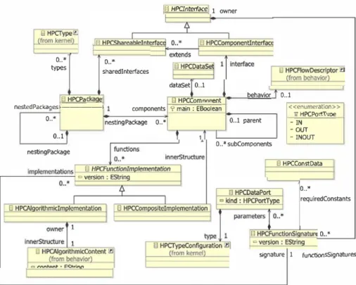
The Structure package of the meta-model (see Fig. 8) contains primitives to model the structural aspects of the application. It includes common structuring primitives, such as Package, Component, Interface, along with specific prim-itives, such as DataSet. Based on the observed need for structured sets of physical constants values, often used as tuning mechanisms of a numeric schema, we included in the meta-model the notion of DataSet, which models sets of strongly typed data, built upon custom base types. The
DataSet concept was introduced to make sure that
physi-cal constants are managed properly, i.e., that their values are consistent over the whole application.
Fig. 8 Package structure from HPCMLn o .. • types sharedlnterfaces o .. • g HPCinteJface 1 owner dataSet 0 .. 1
l;I HPCPa e El HPCCom ent behavior 0 .. 1
nestedPackagesf---f components 'i' main : EBoolean <<enumeratlon>> 11 HPCPo.+'T\•= -IN o .. • nestlngPackage o .. • 0 .. 1 parent 0 .. 1 nestingPackage 3.1.3 Behavior package
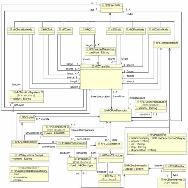
One of the central packages in our meta-model is the Behav
ior package presented in Fig. 9. It gathers behavior-specific building blocks to define the flow of an application by composing and referencing structural building blocks. The current practice in the development of HPC applications ori ented us toward a formalism inspired by UML and SysML like activity diagrams, because they offer a convenient mix of data flow and control flow. Accordingly, this package allows us to model:
Control flow-to model the control graph of the appli cation in terms of oriented graphs formed of nodes (behavior-intensive activities) and transitions (to model the behavior flow between nodes).
Dataflows-to model the data flow within an application. The specification is done in terms of fonctions called and their flow. The fonctions are connected using communi cation ports, which offer means for conveying variables issued from some data set, parameters of the current data flow or some local variables.
-Aspects-to facilitate the separation of concems between the main numerical model and side concems such as numerical validation or output management, we intro duced concepts (e.g., HPCAspect) that support an aspect-based approach [35].
Given its target domain, our DSML needed parallel programrning- specific primitives. The definition of these
O •. • subComponents -OUT -INOUT 0 HPCConstData O .. * requlredC.Onstants o .. • signature 1 functionsSignatures
pnm1t1ves is inspired by existing parallel design patterns [33] and in-house libraries using parallel programrning. Our metamodel contains the following main primitives to model parallel aspects:
Task parallelism-to model parallel tasks. HPCFork and HPCJ o in primitives serve to achieve the modeling of this parallelism.
Domain decomposition (HPCSetEnumerator)-to decompose the domain on which the computing is per formed into sub-domains, so that each of these sub domains may be assigned to a distinct physical execution unit. In a real setting, perforrning the computation on a grid element requires access to (connex) grid elements. In
such a case, the dependencies are explicitly captured at the model level and can be exploited during code genera tion, for instance by defining code generation patterns that make local copies with dummy grid elements, in order to minirnize the resource- consuming communications.
Parallel loops (HPCParallelFor)-to model parallel iterations.
To capture the variety in terms of dependencies between iterations in a parallel loop, we introduce the possibility to distinguish between two kinds of iterations. On the one side, there are iterations without outputs between iteration steps (but with possible access to the same data), with accumu lation of the iteration (which therefore requires a reduction operation in order to recombine the result after each itera tion). On the other side, there are more complex iterations
in 1 out 1 ElHPCFlo� 1 .. * Il nodes 1 1 1 1
1 13 HPCFunctlonNode 1 1 13 HPCFork 1 13 HPCJoln 1 1 13 HPC!f 1 13 HPŒndlf 1 1 13 HPCAnalNode 1 13 HPClnltlalNode 1
13 HPCOlm="'teNode 1 targets 2 .. * 1 fl HPCGuardedTransition 1 ° oond�ion : EStrina taraet 1 source � source 1 2 .. • § HPCTransition targe! 1 � 1 source source 2 .. • taraet 2 .. • 1 .,�.,. source 1 1 target target 1 1 source functlon 1 source
1 13 HPCFunctlonSignature 21 lfrom structurel 1 lnsei1!onlocatlon o .. *transitions
1 ° version : EStrlna 1 innerStructure
1 § HPCFunctionSignature'.!11
l L.,behavior 1 (frorn structurel
1 13 HPCAowDescr1otor 1 ° version : EStrina
L.,_
- -î
_j 1§ HPCAs signature 0 .. 1 o .. •aspects ''---1� § HPCCornponent l!l o .. •1
.
1 /frorn structurel 1 requiredCornponents servicelocatîon1 � main : EBoolean 1
1 1 o ..
•!
connectionsEl HPCFu 1 O .. 7 g HPCDataPortConnectod
connections
fl HPCAJaorithmicContent 1 produ�
11
�umero .. • data 1 § HPCDatalnstance port
?
1 1 D HPCMeshStructure 1 § HPCJ>arallelFor 0 dataDependency : HPCloopDependenceCategory o loopvar : EString 0 in� : EString o step : EString o stooeondition : EStrlng -0 oontent : EStrfng 1 ËI HPCDataPort C!IL
_J�structurel
J
0 kind : HPCPortTVOP 1 § HPCSetEnumerator 1 iteratori § HPCSetlterator 1 <<enumeratlon>>
1;t HPCLoonl'lPnPndenœCateoorv
-none � set O .. l -structure 0 .. 1
1 a stencil : EStrina 1r- --::1
1 l type
• accumulation
• oomolex
Fig. 9 Package behavior from HPCMLn
where the dependencies between iteration steps go beyond simple data accumulators. Capturing the information on the kind of iteration is critical when generating code and deciding on the application deployment.
Let us stress here that, as in the case of any language defin ition, the primitives presented here do not preclude their bad usage. In particular, in the case of task parallelism expressed at model level, we need to check afterward for possible dead locks or possible race conditions. One possibility would be to use symbolic execution libraries.
3.1.4 Others packages
In addition to the three packages, we have presented HPCML that contains three other packages:
1 /from kernen 13 HPCMesh "' § HPCElementType i?l
1 1 lfrorn kemel\
The output package provides concepts for specifying in an abstract way outputs of a simulation code. Output data of a simulation code can be gigantic. Different storage formats and ways of collecting outputs exist. Abstract ing these aspects allows us to adapt easily to ail these options.
The validation package provides concepts to specify properties of model elements such as post-conditions, pre conditions or test methods based on aspect-oriented tech niques.
The parametric package offers ail the concepts required to design pararnetric studies. The idea here is also to benefit from the large amount of parallelism that can be extracted from these studies and to generate tailored simulation appli cations to exploit it.
(a) (b)
Fig. 10 Concrete syntaxes for Fork and Join in HPCML. a HPCFork. b HPCJoin
3.2 Concrete syntax definition
This section gives an insight into the concrete syntax def inition of HPCML. The concrete syntax definition is often a rather neglected issue, probably because presenting it requires a lot of lengthy uninteresting details. Without going into a throughout syntactic description, we present here some principles that guided our choices.
The graphical syntax of a modeling language is a very
important premise for its adoption. As stressed by [43],
"research in diagrammatic reasoning shows that the form of representations has an equal, if not greater, influence on cognitive effectiveness as their content." Aware of the importance of the graphical representation, we designed it by applying Moody's theory [43] which encompasses nine general principles to conceive cognitively efficient graphical notations. These principles range from the need for percep tual discrirninability and semantic transparency to the need for a cognitive integration (for a detailed overview of these principles, the reader is referred to the paper [43]).
To illustrate the impact of applying this theory on the
graphical syntax of HPCML, let us refer to the join andfork
concepts. Figure 10 illustrates comparatively the symbols
representing these concepts. The symbols we have chosen are inspired by symbols frequently encountered in many languages to represent synchronization (e.g., UML activ ity diagrams). Contrary to these other languages that use the same symbol for both concepts, we chose to graphi cally differentiate them while also improving their semantic
transparency (principles 2 and 3 in [43]). The dashed lines
represent potential incoming and outgoing transitions. The inner part of the fork is composed of several small blocks expressing the decomposition into several execution flows. On the contrary, the inner part of the join is composed of one
(a)
SetEnumerator: « iterator.name »
<< innerSt-ructure>>
unique block expressing the merging of the different execu tion flow into one.
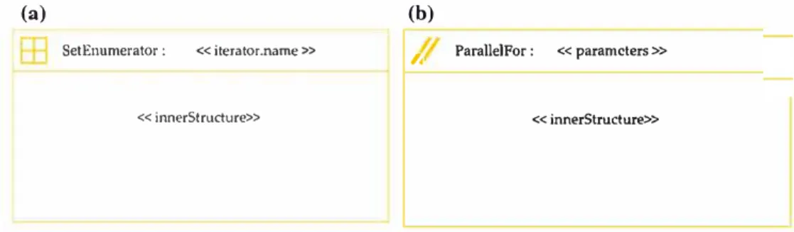
Another example of our design choices in terms of con crete syntax is illustrated in Fig. 11. The HPCSetEnumerator symbol uses a rectangular shape to recall the drawing zone as it can contain an inner structure sirnilar to the overall dia gram. The icon present at the top left part of the diagram suggests the decomposition of a domain (the big square) into sub-domains (the four small inner square).
The right side of Fig. 11 illustrates the symbol for an HPC
ParallelFor. Its graphical representation is intentionally close
to the one of HPCSetEnumerator, as the two concepts are
semantically close and are derived from the same concept the H PCCompositeNode. The icon present at the top left zone
is different at this time and suggests the parallel semantic of a HPCParallelFor.
This section presented HPCML, the domain-specific mod eling language dedicated to high-performance numerical simulation applications. We looked at both the abstract and concrete syntax of this language. Section 5 will give another glimpse of this language through some examples. Before that, we will focus in the next section on an overview of the tool ing we have developed to support the MDE4HPC approach andHPCML.
4 ArchiMDE the tool
Only a true integrated development environment (IDE) bring ing together ail the services needed by the various skills taking part in development would be in a position to respond
to the requirements of the MDE4HPC approach. Such an
IDE would, among other things, have to manage modeling activities for the various skills, for the transformation of mod els, validation, code generation, compilation, debugging and version management.
This section presents the main outlines of the ArchiMDE (pronounced ar-shi-med) tool, an IDE implementing HPCMLn language and following the recommendations of the MDE4HPC approach. After a presentation of its software architecture and the Paprika tool that it includes, we detail
(b)
I ParallelFor : « paramcters » « innerStructure»
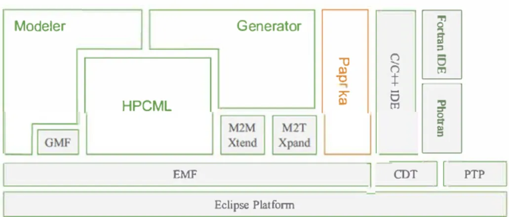
Fig. 12 Software architecture
ofArchiMDE Modeler Generator
"'O QI -0 � :j:
[I]
HPCML 7' QIs
[!]
tI1the development process associated with it that leads to the generation of applications based on the Arcane [25] platform. Arcane is a software development framework for 2D and 3D numerical simulation codes that handles the mesh manage ment and the parallelism strategy. We also address problems of implementing integration of low-level algorithmic with models.
One advantage of MBSD is that there exists a whole panel of tools enabling you to implement approaches based on it. Arnong this panel, you find tools that more or less faithfully implement OMG standards, like the set of projects under the Eclipse Modeling Project [57].
Our choice went in favor of the Eclipse platform [17]
as it has a number of interesting characteristics in addi tion to its predispositions for MBSD through the Eclipse Modeling Project that focuses on the evolution and promo tion of model-driven development technologies. At its core,
the Eclipse Modeling Framework (EMF) [57] provides a
metamodeling language known as ECore. ECore is a meta model whose specification cornes close to the essential MOF
standardized by the OMG [27]. The implementation of the
HPCML metamodel within AchiMDE is based on ECore. Figure 12 offers a simplified view of ArchiMDE's soft ware architecture. In addition to the components we have just mentioned, there are components that take charge of mode! transformations (Xtend, Xpand) as well as the Graphical Modeling Framework (GMF) that provides a development approach based on models to implement the concrete syntax of a metamodel. In what follows, we describe the Paprika component in detail.
4.1 Paprika studio
During previous works, we have already used MBSD to improve the development of numerical simulation software
thanks to the Paprika tooling [ 46]. This tool aims to facilitate
the creation and maintenance of GUI dedicated to the editing of data sets used to parametrize simulation codes.
EMF CDT
11
PTPEclipse Platform
The use of Paprika relies on a two-stage process. The first stage of a Paprika development is the modeling of the structure and the constraints specific to the data set required by the target simulation application. This step is performed according to the Paprika:Numerical metamodel which was defined with the ECore metamodel. Its complete definition is available in [ 46]. The two basic concepts of this metamodel are types (Type) and data (AbstractData). Complex types can be constructed by combining or extending the simple basic types provided by Paprika. One of the special features of this metamodel is that it provides a strong typing system: An existing type can be combined with a physical unit to create highly specific data types.
Once the Numerical mode! has been defined, the sec ond stage of the process offers two possibilities. In the first case, Paprika can generate a GUI based either on the Google Web Toolkit (GWT) [28] or on the Standard Widget Toolkit (SWT) [47] allowing the final user to create and edit data sets respecting the structure and constraints defined in this mode! from the previous step. In the second case, Paprika provides a generic editor capable of editing data sets from any type of Numerical mode!. Nassiet et al. [ 46] provide fur ther details on these two approaches, especially regarding their advantages and drawbacks. Overall, ArchiMDE reuses and integrates Paprika thanks to a set of mode! transforma tions.
4.2 Tool operation
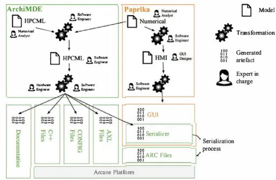
The internai process of theArchiMDE tool is shown in Fig. 13 through the sequencing of the various transformations of models on which it is based. We provide several points of view, also known as perspectives (see also Fig. 3), on the models adapted to the various skill profiles of the partici pants in the development of a simulation application: Applied mathematicians are able to take advantage of perspectives to implement a numerical schema as independently as possible from the platform; GUI developers benefit from perspec tives for the management of inputs/outputs of the simulation
Fig. 13 ArchiMDE transformation process ArchiMDE
[j
HPCMLA�=�
� Numcrical ---.� �Ana.ly&tW
!
[j
Mode!#
Transformationr"'b\
HPCML � so-,..LJ
!
�Eog,ne<r 100 011 010 001 Generated artefact � 1/aJdwan, � � Softwar• � F.nginettV �
F.ngineicr 100m
GUI 001 100m
Serializer 001 100 mARCFiles 001 Serialization process Expert in charge Arcane Platformcode; finally, through transformations, software developers determine how abstract models designed by applied mathe maticians can be translated into executable code for a target platform.
Regarding software target platform, the current version of ArchiMDE is capable of generating applications based on the Arcane framework [25]. Figure 13 shows ail the software artifacts needed to create an Arcane application and how they are generated via model transformations. Generally, there is duplication of data between the source code of a simulation code and the associated graphie interface to edit its data set. As the latter are most often written in different program rning languages, a serialization mechanism must be set up to establish communication between the two applications. As the Paprika tool does not know how these data sets must be generated, it does not allow the data set editor serializer to be generated automatically. Although this stage is elementary, it was always done manually. Now ArchiMDE has a global vision of the application and can thus generate this serial izer. Thanks to that serializer, ARC configuration files (data set format for Arcane) can be created (see Fig. 13). This example clearly shows that ArchiMDE allows the various developer profiles to focus on their core skill while also facil itating the exchange and reuse of data between the various skills.
Although Fig. 13 represents the sequencing of the various
transformations more or less sequentially, a frequently used technique of iteration on the first transformations can also be
adopted (HPCML merged with Paprika:Numerical) with
out using lower-level transformations (HPCML to Arcane
or Paprika:Numerical to Paprika:HMI). This flexibility
dur-ing development complies with the recommendations of the MDE4HPC approach.
4.3 Low-level algorithmic management
The HPCML version presented here does not offer a formal ism to define an HPCAlgori thmicContent butjust the constraints on the formalism to be used. There are several ways in ArchiMDE to manage integration of the low-level algorithrnic (expressed in the formalism provided by the Arcane platform) with high-level models. lndeed, we have identified four generation management approaches: direct, incremental, algorithrnic model and synchronization. For fur ther details regarding the advantages and drawbacks of each approach, see [49].
As our objective was to start by defining and vali
dating the HPCMLn language, which has a considerable
impact on the development of the tool, we have selected the direct generation approach. In this configuration, the tar
get platform language (here Arcane) is used to describe the
HPCAlgori thmicContents. A String attribute is used to store the content. On generation, this content is used as such by model transformations.
Although it is only a prototype, this tool was used as a medium for practical works at the international summer school organized by the CEA, EDF and Inria in 2010. This event, the topic of which was "Sustainable High Performance Computing", provided the opportunity to have the tool tested with more than 40 people. The considerable feedback on rnissing or unsuitable concepts contributed to upgrading the ArchiMDE tool as well as the HPCMLn language.
5 Evaluation and discussions
In this section, we present the evaluation we have per-formed for our approach and we take advantage of the conclusions raised by this evaluation to more largely dis-cuss on MDE4HPC in Sect. 5.4. The evaluation of the
MDE4HPC approach was performed in two stages. First
we used the ArchiMDE tool to redevelop the simplified Lagrangian hydrodynamics code introduced in [25]. The evaluation of this development, the results of which have been published in [50], enabled us to validate the fact that it is possible to use the MDE4HPC approach to generating viable code in terms of performance while obtaining a reduction in maintenance costs. Secondly we wanted to evaluate the capacity of HPCMLnlanguage to model an application both
used in production and based on another physical domain. This section presents the results of this new evaluation. 5.1 Presentation of the simulated system
The simulation code introduced in this section is based on a code used in production that serves to simulate the diffrac-tion of a plane electromagnetic wave by complex 3D objects composed of several materials. These materials may be con-ducting or dielectric. In our case, we focused on concon-ducting mono-material 3D objects.
5.1.1 Problem
A perfectly conducting body is illuminated by an incident harmonic plane wave. The presence of this obstacle modifies the incident field: This is what is known as the diffraction phe-nomenon. Our goal is to compute the electric current induced by this incident wave on the object’s surface.
5.1.2 Physical model
The physical model chosen for the study of this phenomenon is based on Maxwell’s equations [29].
5.1.3 Mathematical models for resolution
For the resolution, we rely on a formulation based on the sur-face integral equations of Maxwell’s equations in harmonic regime. We thus reduce a three-dimensional problem on an unbounded domain to a boundary problem posed on a sur-face.
The integral equations in a variational formulation that we propose to resolve are the conventional electric-field inte-gral equations (EFIE) [18]. We then use the finite element method to solve these integral equations. The main stages in constructing a finite elements model are as follows [48]:
– discretization of the continuous medium into sub-domains (meshing);
– construction of the approximation by sub-domain (choice of the finite elements);
– computation of the elementary matrices corresponding to the variational formulation of the problem;
– assembly of elementary matrices; – consideration for boundary conditions;
– resolution of the system of linear equations of type Ax= b.
5.2 Modeling of the application with HPCML
5.2.1 Modeling process
The existing code, from which the models presented in this section are derived, is written in Fortran 90 and uses the Mes-sage Passing Interface MPI [56] standard (Message Passing Interface) [56] for expressing parallelism. The rise of the abstraction level when (retro)modeling was performed could only be achieved with participation from mathematicians who passed on their knowledge during more or less formal-ized discussions. Even if the approach adopted (retrodesign) in this case study is not identical to a new development, we were able to identify a general process that seemed to be suited to both cases.
The first stage of this process, which takes place during discussions on the mathematical model, involves drawing on a sheet of paper the hierarchy and sequencing of func-tions using a simplified version of the HPCML concrete syntax. Once this first rough sketch is completed, we can determine what functions are available in the existing com-ponents. Then we can model the application by following the sequence described in the rough sketch we just estab-lished (sequencing of functions and their origins). Finally, a global refactoring of a subset of the application is performed to determine whether all the potential sources of parallelism have been identified.
5.2.2 General overview of the models
Figure14presents a high-level structural view of the appli-cation by showing the organization of the main components. Two main packages (HPCPackage) can be seen: The first one contains the components specific to the simulation code we are developing (EMPrototypeMDE Project), and the second contains components providing generic numerical services (resolution of linear system and integration).
Figure 14also shows part of the structure of the appli-cation’s main component (HPCComponent
EMPrototype-MDE with the main property true) and especially the
definition of its interface (HPCComponentInterface). It is interesting to note that even on the first
hierarchi-" fil platform:/resource/fr.cea.archimde.hpcml.core/model/EMPrototypeMOE.xmi • + HPC Package EMPrototypeMDE Project
• � HPC Component EMPrototypeMDE
,,,
+
HPC Compone:nt (nterface Property 06ctiption Main Name Volue!'� Component simulating the diffraction of a plane electromagnetic wave b) liiitrue
ü EMPrototypeMDE " + HPC Function Signature: gentrailnit
� � HPC Data Port mesh
,,,
+
HPC Function Signature computeContributionsMatrix � � HPC Data Port mesh� � HPC Data Port contributionsMatrix
"
+
HPC Function Signature computeZCom� � HPC Data Port incidenceAngle
� � HPC Data Port zComPolarl
t> --} HPC Data Port zComPolar2
� � HPC Data Port mesh
�
+
HPC Data Set.,O. HPC Algorithmic lmplcmcntation -0,. HPC Composite lmplementation -0-HPC Composite Implementation C>
+
HPC Flow Oesc,iptor � � HPC Component ComputeZCom b "9-HPC Component ComputeContributionsMatrix " + HPC Package numerical � � HPC Component Solver � � HPC Component lntegration�
+
HPC Structure Type CellRelation+ HPC Array Type SymmetricMatrix
t> i) platfotm:/resource/fr.cea.11rchimde:.hpcml.core/modl!:l/hpcml_v3.e:core
C>
i
platform:/resourcc/fr.cea.archimdc,hpcml.core/modcl/Modcllibra,y.xmiFig. 14 Main view of the structural part
ParallelFor : (angle, angleStart, angleStop)
i
-f(x solveSystem
Fig. 15 HPCFlowDescriptor of the EMPrototypeMDE compo
nent
cal level of the EMPrototypeMDE application component, you see both sorts of irnplementations (HPCComposite Implementation and HPCAlgorithmicContent).
Nesting Package Parent
tif HPC Package EMPrototypeMDE Project
i'î,
UR!
...
The structural view follows the master/detai/,s UI pattern with two zones: a tree on the left representing the hierarchy of the model elements and on the right the details of the selected model element.
Concerning behavior modeling of the application, Fig. 15
shows the HPCFlowDescriptor of the EMPrototype
MDE component where only the execution flow is visible.
An HPCFlowDescriptor allows to specify the execu tion flow of an application or a function with a semantic close to activity diagrams in UML. This one uses several forms of expression of parallelism: an HPCParallelFor (same processing applied to different data) and the couple HPCFork/HPCJoin (different processing concurrently). Note that the interleaving of several constructions to express parallelism allows them to be combined to obtain even more parallelism.
5. 2. 3 Calculation of the matrix of contributions
Figure 16 gives a view of how the ComputeContribu
tionsMatrix component, which is a sub-component of the EMPrototypeMDE component, is used to refine the behavior
specification of its parent.
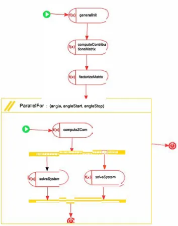
Meanwhile Fig. 17 shows the HPCF 1 owDescr iptor of this component with its control flow. Sorne new elements as compared to the HPCFlowDescriptor of the EMProto
typeMDE component present in Fig. 15 can be distinguished
here.
First the ComputeContributionsMatrix component is a sub-component of the EMPrototypeMDE component, and
Modd
,. l-9-HPC Component ComputeCcntributionsMatri:xl
,.
+
HPC Component Interface,.
+
HPC Function Signature computeGaussWeightsForOisjointsElements1> ,,r), HPC Data Port xGauss � ? HPC D•t• Port wG•u»
1> + HPC Functîon Signature computeGaussWeightsForMingled8ements
1> + HPC Function Signature computeGaussWeightsForEle.mentsWithOne.NodelnCommon
I> + HPC Function Signature computeGaussWeightsForElementsWithOneVert.icdnCommon
,
+
HPC Function Signature getCellRelation 1> .,O. HPC Data Port celll� ? HPC D•t• Port cell2 � ? HPC Data Port cellRelation
,.
+
HPC Function Signature computeElementaryMatrix � ? HPC Data Port celll� ? HPC Data Port cell2 I> {,, HPC Data Port efementaryMatrix � ? HPC Data Port xGauss � ? HPC Data Port wG,uss
,. + HPC Fundion Signature addElementa.ryMatrixContribution
� ? HPC Data Port celll
� ? HPC Data Port cell2
I> .,O. HPC Data Port el.ementaryMatrix � ? HPC Data Port cellRelation
, + HPC Data Set
• + Data Block integrationPrecision
+Data NptTR3OneNode +Dat> NptTR3On,V,rtice
+Data NptTR3Disjoint
+Data NptTR3Mingled ,O. HPC Algorithmic Implerntntation
,O. HPC AJgorithmic Implemtntation
� HPC Algorithmic (mplem,ntation
,O. HPC Algorithmic Implerntnt.ation ,O. HPC AJgorithmic Implemtntation � HPC Composite lmplementation Propcrties URI Description Main Name
Composant responsable de la construction de fa matrice conte.na
El
ComputeContributionsMatrix Nesting Package I HPC Package ArfeneMOE Project
Fig. 16 View of the structural part of the ComputeContributionsMatrix component
as a result, its HPCFlowDescriptor has an HPC FunctionSignature that results from one of the HPC
FunctionSignatures of the EMPrototypeMDE com
ponent interface: It is the computeContributionsMatrix sig
nature whose declaration is visible in Fig. 14.
Second you can see an example of the third way of express ing parallelism: the HPCSetEnumerator. Here we even find the interleaving of two HPCSetEnumerators since we wish to calculate the contribution of each mesh with respect to the other meshes. It is not visible on the figure since it is not defined through this view, but the value of s tenci 1 (the mode! element describing the memory depen dencies) for these two HPCSetEnumerators is all, since
each mesh will have to access all the other meshes, at least in read (HPCDataPort of the relation set in mode IN). This is typically a case that will pose more problems on genera tion of implementation toward architectures with distributed memory than on those with shared memory. In the case of shared memory, it can be imagined that ail the execution units access mesh data by their common memory. In the second case, a number of solutions can be envisaged one of which would be to replicate the meshing data on the memory of each execution unit. Of course, this solution can only be consid ered if the memory of the execution units is big enough to receive mesh data.
Finally, Fig. 17 contains the last control flow structure
that was not presented: conditional connections (HPCI f and HPCEndif).
5.3 Benchmarks
The modeled application was used to generate an executable
program based on the Arcane framework as described in Sect.
4. This section presents the results of benchmarks performed
with this program (based on C++ with Arcane) and the orig
inal version of the application (based on Fortran with MPI)
on the TeralOO supercomputer-a Bull supercomputer com posed of 4370 node servers with 138 368 Intel Xeon cores, an Infiniband interconnect system with a performance of 1,05 petaflops.
First we conducted benchmark to compare the two appli cations as we wanted to see whether the application produced with the MDE4HPC approach was at least as efficient as the application developed in a traditional way. This benchmark was performed on an object with 50,000 meshes. The results, which are presented in Fig. 18, are extremely encouraging. It can be seen that the execution time of the EMPrototype pro duction version and that obtained with MDE4HPC, called
EMPrototypeMDE, are very much similar. Despite being functionally equivalent, the difference in tenus of
frame-Fig. 17 HPCFlowDescriptor of the ComputeContributionsMatrix component 1500 1000 ·.;; 500 4 8 SetEnumerator : 0011 SetEnumerator : œ112 -+- EMPrototype _._ EMPrototypeMDE 16 32 Number of Processors
Fig. 18 EMPrototypeMDE: computation timecomparisons
works and languages (before the assembler [sic]) explains the slight differences in performance.
Second we conducted another benchmark on EMPro
totypeMDE alone this time to assess its scalability. This
benchmark used two test cases, the first one with an object
addElemenlaty f(x MstrixContri:>u·
@
don 35r--r-r-�r---;::::==========::::::;-i
30 25 o. 20 ;::s g- 15 10 5 � Linear � EMPrototypeMDE Casel � EMPrototypeMDE Case2 Number of Processors Fig. 19 EMPrototypeMDE: ScaJability studycomposed of 10,000 meshes and the second one with an object composed of 50,000 meshes. The results exposed in Fig. 19 show a noteworthy speedup on the first case (Case l) tending to show the operational nature of the generation of scalable code from models. This is al! the more true in
so far as this scalability improves as the scale of the prob-lem increases (Case 2). But we must clarify that scalability obtained here is rather due to the algorithm used than the development approach.
5.4 Experiments takeaway and discussion
In this section, we presented a two-stage evaluation of the
MDE4HPC approach. The criteria mainly addressed in this
evaluation are the scalability and the viability of MDE4HPC. However, our approach provides improvements outside of the criteria assessed here. For example, the HPCML lan-guage is especially useful in formalizing the specification of
simulation codes. This characteristic is a decisive factor in
knowledge capitalization and the transmission of skills. This case study enabled us to better understand the behav-ior of the HPCML language when modeling a different physical domain and fits in with our previous works where we showed viability in terms of performance of the code gen-erated by the MDE4HPC approach as well as a reduction in maintenance costs, especially when porting an application to a new supercomputer [50].
The reduction in terms of maintenance costs was not eval-uated again in this new evaluation mainly due to resource constraints. This evaluation is part of our future plans and will be conducted after the deployment of the next genera-tion of supercomputers. Nevertheless, the preliminary results obtained in the different experiments already performed, con-vinced us that the benefits induced by the use of automation and by the capitalization of the best practices, if gener-alized to an entire organization, would lead to substantial gains.
The model of the application presented here uses all the concepts we proposed to express parallelism. This model thus provides an adequate basis to run the experimentation needed to define the HPCMLelayer as addressed later when
discussing future perspectives.
In order to validate the transformation chains and the code generation, as part of the future work, we propose the
uncer-tainty quantification—classical technique in HPC, adapted to
the model-based context. It consists in making some paramet-ric studies on the models, because several numeparamet-rical models can solve on physical one, but also on the optimization of the code generator. Based on these studies, it would be pos-sible to quantify the ratio precision/performance to get the best compromise, depending on the specific needs, in terms of deadline, performance or supercomputer availability con-straints.
The performed evaluation allowed us to experience several of the benefits of the use of model-driven development in the context of HPC. In the order of their perceived importance these benefits are:
– MDD enables a selective view of the system and the sep-aration of concerns, through the layered definition used in MDE4HPC;
– The use of code generators that lead to a high quality of the obtained code (in terms of performance);
– Allows for domain-specific languages, with a look and feel close to the domain-specific culture to be used instead of raw programming code, thus increasing the accessibil-ity of the domain experts and reducing the cognitive effort required for developing applications;
– Facilitates the apprehension of an HPC application, through offering various abstract views of the system. Up to this stage, our project did not had the opportunity to take advantage of lots of other promising openings offered by the introduction of models in this context such as reasoning on the abstract model to perform early verification and vali-dation, to investigate non-functional properties of the model, etc. Even so, the results obtained up to this stage make us very eager to investigate further on such openings as part of our future work. The next section complements the quick overview of the model-driven engineering particular benefits that we exploited in our approach.
6 Lessons learned
In the previous sections, we introduced MDE4HPC—our approach for adding abstraction in HPC applications by using MDE techniques. In addition to that, a set of domain-specific languages stemming from our method with a focus on HPCMLn, the toolset supporting our framework and
finally a multi-dimensional validation that assessed the rele-vance of the current approach have been introduced.
We had the chance of being involved in a full-fledged experiment lasting more than four years, applying MDE prin-ciples in high-performance computing. Looking back, we realize that some of the choices we made (with greater or lesser awareness), although seeming reasonable at the time, may be subject to improvement.
In the present section, we analyze the experience we gained and draw a set of lessons from our experimenta-tion of MBSD on a new applicaexperimenta-tion domain. Through these lessons learned, we hope to contribute to a wider dissemina-tion of MBSD in a higher number of applicadissemina-tion domains. To establish these lessons learned, we adopted the perspec-tives of both the end user of our solution (developer of HPC applications: mainly the numerical analyst presented in Fig.3) and the developer of MBSD solutions (mainly the software engineer presented in Fig.3). The current analy-sis emerges from experience and is in line with other efforts [4,16,30,31,37,42] to capitalize on insights, awareness and best practices obtained from concrete settings.