Any correspondence concerning this service should be sent
to the repository administrator:
[email protected]
This is an author’s version published in:
http://oatao.univ-toulouse.fr/26660
To cite this version: Rival, G. and Dantras, E. and Paulmier, T.
Electronic irradiation ageing in the vicinity of glass transition
temperature for PEEK space applications. (2020) Polymer
Degradation and Stability. 109305. ISSN 0141-3910
Official URL
DOI :
https://doi.org/10.1016/j.polymdegradstab.2020.109305
Open Archive Toulouse Archive Ouverte
OATAO is an open access repository that collects the work of Toulouse
researchers and makes it freely available over the web where possible
Electronic irradiation ageing in the vicinity of glass transition
temperature for PEEK space applications
G. Rival
a. b,E.
Dantras
a.•.T. Paulmier
ba CIRIMAT- Université Toulouse III Paul Sabatier, Physique des Polymères, 118 Route de Narbonne, 31062, Toulouse, France b ONERA - DPHY, The French Aerospace Lab, F-31055, Toulouse, France
ABSTRACT Keywords: Irradiation PEEK Structure-properties relationship Temperature Thermoplastic polymer
Satellites in space environment are subject to several environmental constraints. In the case of polymer materials, e!ectronic irradiations can induce premature ageing which can lead to a shorter lifetime for the satellite. Moreover, synergistic effects between temperature and irradiation can occur and enhance this ageing. A previous study showed that PolyEtherEtherKetone (PEEK), a newly used polymer in space industry, presents great radiation tolerance properties. Nonetheless, it was necessary to investigate the influence of temperature factor on its ageing. This study focuses on the comparison of PEEK samples aged at two temperatures: room temperature and 165'C. Irradiations have been performed under high vacuum and with a mono-energetic electron beam. They led ta doses representative of 15 years of exposure to geostationary electronic environment. The comparison between bath types of samples showed that increase in irradiation temperature have a significant impact on ageing kinetics. In particular, analyses revealed a higher cross-linking density for 165'C irradiated samples which has been associated with a higher recombination rate of radicals due ta amorphous phase mobility increase above glass transition.
1. Introduction
Polyrners used in satellite manufacturing are exposed, in Geo stationary Earth Orbit (GEO), to several environmental stresses like high-vacuum, UV and gamma radiations, thermal cycling or irra diation by high-energy partiel es ( e.g. protons, electrons, ... ). Thus, it is essential to understand how these different ageing factors will impact the polymer properties. ln the case of electronic irradia tions, two major issues can be pointed out. The first one is due to low-energy electrons which induce electrical charging of polymer surface and lead to electrostatic discharge phenomena responsible of many spacecraft failures [ 1 ]. The second one is due to high energy electrons which depose energy in polymer volume and induce different phenomena like physico-chemical ageing [2,3] or radiation-induced conductivity [4,5]. Moreover, polymers have to cope with temperature variations which can induce synergistic effects with electronic irradiations. For example, an increase in the polymer temperature enhances its electrical conductivity and therefore, limits the accumulation of charges due to low-energy
* Corresponding author.
E-mail address: [email protected] (E. Dantras). https://doi.org/10.1016/j.polymdegradstab.2020.109305
electrons. But also, increasing temperature can also exacerbate the radiative ageing of a polymer and significantly reduce its lifetime.
ln the literature, several studies report the influence of tem perature on radiative ageing [6-8]. Kudoh et al. showed on different polymeric materials ( epoxy-based GFRP, PMMA and PTFE) that irradiation temperature has an influence on ageing even by remaining below the glass transition temperature [9]. lndeed, a decrease in irradiation temperature delays the evolution of me chanical properties due to the lowest mobility of macromolecules. In their study, Mélot et al. followed, by Fourier Transform InfraRed spectroscopy, the ageing of aliphatic polymers irradiated at low temperature (i.e. at 8 K) [10]. Like Kudoh et al., they observed a significant influence of temperature on radiative ageing but studied as well the effect of annealing after irradiation at 8 K. As a result, they showed that, even after the end of irradiation, an increase in temperature can activate the macromolecule mobility and promote the creation of new chemical bonds due to remaining radicals. Moreover, the evolution of ageing with temperature can be very non-monotonous as showed by Oshima et al. for PTFE [11,12]. They observed a chain-scission phenomenon when irradiations are performed below melting temperature, a cross-linking
phenomenon just above the melting temperature and a depoly merisation phenomenon at higher temperature. However, in case of space applications, the authors did not find radiative-ageing studies which take into account the influence of the temperature factor.
This study focuses on a newly-used polymer in space industry: PolyEtherEtherKetone (PEEK). In particular, this polymer is used for structural applications in the form of PEEK/Carbon fibre composites such as in the articulated arm of the International Space Station [13] or for mechanical support applications in scientific instruments such as the search-coil magnetometer (SCM) used in the Parker Solar Probe mission [14]. In a previous study [15], PEEK has been exposed, under high-vacuum and at room temperature, to ionising electronic radiation in order to investigate its ageing behaviour for space applications. This study showed that electronic irradiations induce changes of both the amorphous phase (cross-linking) and the crystalline phase (amorphisation). In the literature, only one study tried to investigate the synergistic effects of thermal-ageing and radiative-ageing for PEEK in case of nuclear applications [16]. However, the study being focused on the comparison of thermal ageing effect with or without irradiation, no real interpretation is made on the influence of temperature on the radiative ageing. Through this work, we propose to compare the ageing of PEEK at two irradiation temperatures chosen below and above the glass transition temperature: room temperature and 165°C respectively.
For this purpose, a heating sample-holder was developed to maintain samples at a given temperature during the irradiation. The resulting ageing has been analysed through different experi mental approaches in order to probe changes at the macromolec ular scale and link them to property modifications.
2. Materials and methods
2.1. Matena/
PEEK samples used in this study are semi-crystalline films with a thickness of 100 µm. They have been supplied by Victrex and correspond to the Aptiv 1000 grade.
2.2. Experimental simulation of electronic irradiation combined with high-temperature
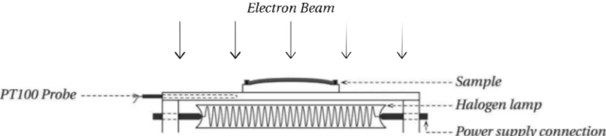
In order to irradiate samples at a controlled temperature, a heating sample-holder has been developed. Fig. 1 shows a sche matic representation of the experimental set-up made for this purpose.
It consists of a 5 mm copper plate heated on the back by four halogen lamps (Reference: Orbitec R7S 400 W; 240 V) purchased from RS Components and powered by a 150 V; 3 An electrical po wer supply. Irradiations being performed under high-vacuum, the
use of halogen lamps seemed to be the best choice for heating the sample-holder. To measure and control the temperature of the sample-holder, a PT100 sensor was coated with thermal transfer grease and inserted in the copper plate. Finally, samples were placed on curved copper plates to maximise contact with the support and are maintained at the edge by screws. Moreover, a conductive thermal transfer grease was deposited between sam ples and copper support to optimise heat transfer.
The procedure of irradiations at room temperature and dose calculations have been already described in a previous study [15]. In the case of irradiations at 165°C, irradiation conditions (apart
from sample temperature) and procedure are the same. They are summarised thereafter.
Irradiations were carried out in the SIRENE facility (ONERA, Toulouse, France). Samples were exposed under high-vacuum to a mono-energetic electron beam of 350 keV. Irradiations were ach ieved in less than 60 h thanks to a high beam current density ( up to 60 nA cm-2). The resulting ionising doses D (Gy) were calculated
using equation (1 ). Ali doses mentioned in this study correspond to the average dose over the thickness of samples.
(1)
where '1> represents the total electronic fluence ( electron/cm2), p
the material density (g.cm-3) and dE/dx the electronic stopping power of the material (keV.µm-1).
1.2x10⁷ Gy and 3.4x10⁷ Gy doses have been deposited in each
type of sample (i.e. irradiated at room temperature and 165°C). In
these conditions, the dose profiles are homogeneous over the sample thickness ( the ratio between front and back face doses is about 1.5), allowing to limit uncertainties due to a dose gradient inside samples.
2.3. Differential Scanning Calorimetry
Differential Scanning Calorimetry (DSC) analyses were per formed on a DSC 7 from PerkinElmer. Analyses were carried out under nitrogen flow and involved two heating runs and one cooling run from 50°C to 400°C at a rate ofl0°C.min-1. The temperature of
first-order transitions (i.e. melting temperature Tm and crystal
lisation temperature Tc) was taken at the maximum of the peaks and the glass transition temperature Tg was determined by the
tangent method as well as the heat capacity jump ,Kp, Crystallinity
ratios Xe were calculated from melting enthalpy using equation (2). b.Hm
Xe=
b.Hoo X 100 (2)
where b.Hm is the sample melt enthalpy Q.g-1 ), b.H00 is the
Electron Bearn
1
1 1
1
1
theoretical melt enthalpy of a fully crystalline sample reported for PEEK at 130 J g-1 [17].
2.4. Acetone absorption test
Absorption tests has already proven that they can be used to study the effect of ageing on polymer materials, especially in order to probe changes in the physico-chemical structure [ 15 ]. In the case of PEEK, absorption tests were performed in acetone due to the high equilibrium weight gain in regard of water: Stober and Seferis found a weight gain of ""7% m with acetone [18] white Mensitieri et al. found a weight gain of ""0.5% m with water [19]. Moreover, Stober and Seferis also verified that acetone penetration does not induce sample crystallisation.
The experimental procedure for weighing has already been described in our previous study [15]. We present hereafter the equation for weight gain calculations.
The weight gain (WG) is calculated by equation (3 ).
(3) where m0 is the initial dried mass of the sample.
Moreover, diffusion phenomena in polymer only take place in amorphous phase. Thus, the weight gain is normalised by the quantity of amorphous phase in order to consider a possible crys tallinity ratio evolution. This normalised weight gain (NWG) is obtained by equation ( 4).
NWG (1 - Xc/100) x mo m-mo x 100
with Xe the crystallinity ratio (%) obtained by DSC analyses. 2.5. Dynamic Mechanical Analysis
(4)
Dynamic Mechanical Analysis (DMA) tests were carried out on an ARES G2 strain-controlled rheometer from TA Instruments. Sample dimensions are 35 mm x 10.5 mm. As sample thickness does not allow a good signal-to-noise ratio in shear deformation geometry, they were analysed in tensile geometry mode. Each sample have been studied over the temperature range [-130; 250]°C at a rate of 3°C.min-1. Strain and frequency were fixed at
0.02% and 1 Hz respectively allowing the determination of storage E�(T) and loss E'�(T) moduli. For samples irradiated at room tem perature, the strain used in the initial study was 0.01%. The damping factor tan o is then calculated by the ratio of loss modulus E'�(T) over storage modulus E�(T).
Table 1
2.6. Broadband Dielectric Spectroscopy
Broadband Dielectric Spectroscopy (BDS) is a common tech nique for studying dielectric behaviour of polymers and has already been extensively described [20].
Experiments were carried out on a Novocontrol BDS 4000 spectrometer associated with an Alpha-A impedance analyser. The sample diameter was 30 mm for pristine and room temperature irradiated samples, 20 mm for 165°C irradiated samples. Analyses
were performed over a frequency range of 110-2; 106] Hz and for isotherms going from -150°C to 25o·c by 5·c steps. The complex
impedance z• ( w, T) is used to determine the values of complex permittivity e(w, T) thanks to equation (5).
e"' =e' - ie" = -
-1-iwCoz• (5)
with C0 = � in which e0 is the vacuum permittivity, A is the area of
the sample and e its thickness.
Havriliak-Negami equation was used to analyse dielectric relaxation phenomena observed on loss permittivity [21,22]: e"(w) =eoo + (1 + (iwTHN)"""l"N es - eoo (6)
e00 and e, represent the instantaneous and the equilibrium
permittivities respectively, llttN and �HN the Havriliak-Negami pa
rameters which show the deviation from Debye's relaxation mode!
(aHN is related to the peak width and �HN to its asymmetry at high
frequency) and "HN (s) the Havriliak - Negami relaxation time.
Sub-glass relaxations were fitted with an Arrhenius law ( equa tion (7)).
(7) where Toa (s) is the arrhenian pre-exponential factor, LiH Q.mol-1) is the activation enthalpy of the relaxation and R the ideal gas constant.
Above glass transition, dielectric relaxations were fitted with a Vogel-Tammann-Fulcher (VIF) equation [23-25]:
(8) with -i:o,v ( s) the vogelian pre-exponential factor, "'t ( • c-1) the free
volume thermal expansion coefficient and T 00 ("C) the free volume
activation temperature.
Data extracted from DSC analyses of samples irradiated at Room Temperature (Kr) and irradiated at 165 ·c. 1st and 2nd refers to first and second heating runs respectively.
Îg ti.Cp Îm Xe T, ('C) Q.g-l_•c-1) ('C) (%) ("C) 1st 2nd 1st 2nd 1st 2nd 1st 2nd Pristlne 158 147 0.15 0.14 339 339 34.1 40.1 297 RT Irradiation Dose= 12 MGy 157 150 0.11 0.12 331 333 32.6 33.7 286 Dose-34MGy 159 153 0.16 0.16 318 320 25.8 23.0 269 165"C Irradiation Dose -12 MGy 158 151 0.13 0.12 327 328 30.9 30.6 280 Dose= 34MGy 163 156 0.12 0.14 309 312 26.3 24.3 255
158
§
156
1154
Û 152
0 150
E--s
t,JJ148
146
■
• __________ 0 MGy_
300
.a.
__________ O MGy.
290
Û 280
� 270
E--s
260
250
0
10
20
30
Dose
(MGy)
• __________ 0 MGy _•
Q•
?
__________ 0 MGy♦
◊
!
010
20
30
Dose (MGy)
340
330Û
0 '--'320
310
36
34
32
,--...30
28
;,..ç u26
24
Fig.. 2 .. Calo�imetric parameters extracted from DSC analyses as a function of dose. Full symbols represent room temperature irradiated samples white empty symbols represent 165 C 1rrad1ated samples.
3. Results and discussion
3.1. Impact of irradiation temperature on PEEK physical and chemical structures
To investigate the irradiation temperature influence on the physico-chemical structure of PEEK, DSC analyses were carried out. For purpose of clarity, DSC thermograms are not presented here. Instead, ail the data extracted from these thermograms are re ported in Table 1 and Fig. 2 summarises the evolution of the different calorimetric parameters. Due to internai stresses which increase Tg during the first run, the Tg value presented in Fig. 2 are
extracted from the second runs.
This figure shows that room temperature irradiations and 165 ·c irradiations induce similar evolutions of the PEEK physico-chemical structure. It means that the irradiation temperature does not affect the ageing mechanism under electronic irradiations. It is consistent with Oshima et al. studies on PTFE for which the degradation mechanisms only change above melting temperature [11.12]. Nonetheless, looking at the evolutions of glass transition, melting and crystallisation temperatures, it is evident that 165"C irradia tions accelerate ageing kinetics.
• For the glass transition temperature increase, it has been pre viously associated with a chemical cross-linking phenomenon which occurs in the amorphous phase [15]. With increasing ageing temperature, the faster Tg increase is explained by a
higher cross-link creation. Indeed, irradiations being performed above glass transition temperature, the higher mobility of macromolecules induces a higher recombination rate of radicals and therefore, a greater number of cross-links. By considering a three-phase model ( crystalline phase, mobile amorphous phase and rigid amorphous phase), one can calcula te the mobile amorphous fraction MAF from equation (9).
MAF = àCp / àcg (9)
where ilcg is the heat capacity jump of a 100% amorphous sample reported for PEEK at 0.27 J g-1 K-1 [26]. Finally, the rigid amor phous fraction RAF is calculated by using equation (10).
RAF= 1 -1�0 -MAF (10)
By using the ilCp value of the second heating run, the calculation
ofRAF gives a value of8% for the pristine sample, 18% for the sample irradiated at room temperature (34 MGy), and 24% for the sample irradiated at 165"C (34 MGy). These results show that irradiation tends to increase the rigid amorphous fraction. The rigid amor phous phase is described as a highly entangled amorphous region where the macromolecules don't relax at the glass transition temperature. Thus. the increase in RAF can be explained by cross links which play the role of chemical entanglements and immo bilise a fraction of amorphous phase. Moreover, 165"C irradiation induces a higher increase of the RAF which further confirms the higher cross-linking density.
The influence of this higher density of cross-linking nodes can also be seen through the sample crystallisation; i.e. Tc decreases faster for high-temperature irradiated samples. The higher cross linking density further limits the crystallisability of macromolecules.
• Concerning the crystalline phase evolution, either in room temperature or in 165"C irradiated samples, Tm and Xe decreases are due to the creation of defects in crystallites which can be explained by a decrease in their size. This is consistent with the study ofYoda who observed by X-Ray Diffraction a 15% decrease in the size of PEEK crystallites after electronic irradiation [27].
0 10
*
**
'#(1,:
*ïS"
•
•
•
-tP*-f,t,*
•
*
•
**
**
*
*
Pristi.ne ■ 34 MGy, Thrnd. = RT*
34 MGy, T, .. ,d. = 165"C*
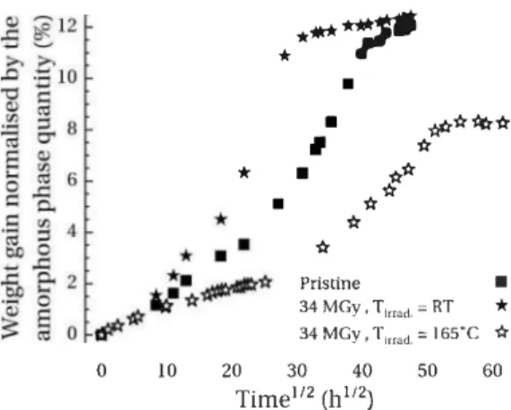
20 30 40 50 60 Time112 (h112)Fig. 3. Weight gain data as a function of time square root for pristine PEEK and for samples irradiated at room temperature and 165"C.
However, after 165°C irradiations, oniy the decrease in T m is
acceierated. It means that the increase in irradiation tempera ture leads to Iess stable crystalline entities but does not affect the crystallinity ratio. As irradiations being performed below the melting temperature, the surface of crystallites ( i.e. at the amorphous/crystaI interface) is probably mostly impacted due to the increase in amorphous phase mobility. Thus, the higher decrease in crystallite stability can be expiain by a higher crea tion of defects mostly at their surface. However, the decrease in Xe remains the same. During the second heating run, Tm value at
a same dose remains lower for high-temperature irradiations. The samples having already melted once, these evolutions have been associated with chemical modifications. Thus, it can be associated with the higher cross-linking density which limits the crystallisation of macromolecules and leads to smaller crystallites.
3.2. Cross-linking density influence on absorption behaviour Fig. 3 shows the normalised weight gain curves for PEEK versus time square root. To emphasise the influence of irradiation tem perature on the acetone absorption behaviour, only samples irra diated at 34 MGy have been studied with this method.
By representing the weight gain data as a function of time square root, a two-stage diffusion phenomenon can easily be identified for the pristine sample where the second stage, which appears at around 25 h 112, has a faster absorption kinetics. In the literature, Bagley and Long were the first to observe this phenom enon [28]. This two-stage mechanism is described as follow: the first part corresponds to a quasi-equilibrium which is reached at the surface of the sample and the second part to the diffusion of the penetrant through the polymer sheet which is assumed to be allowed by the rearrangement of macromolecules in the amor phous phase. i.e. by breaking interchain physical links. However, in this case. for which the second stage is faster than the first one, none of the previous studies provided an equation allowing to mode! this behaviour. For example, the study of Loh et al. [29] suggests a mode! consisting in the sum of two fickian diffusion phenomena but can't fit correctly our data.
Data show that the two studied irradiation temperatures have an opposite influence on the acetone diffusion. It can be explained by the opposite influence of amorphisation and cross-linking. While amorphisation accelerates diffusion kinetics and increases weight gain at equilibrium ( diffusion and retention processes tak ing place in amorphous phase), it has been shown that cross linking has opposite effects [30,31 ]. As already discussed in our previous study [15], the absorption behaviour of room temperature irradiated sample reveais a greater diffusion kinetics in regard to pristine sample. Therefore, the data suggest that amorphisation effects prevail over cross-linking phenomena after room tempera ture irradiations. However, DSC analyses presented before showed that cross-linking density is higher after irradiation at 165 °C while
crystallinity ratio evolution remains similar for both irradiation conditions. Thus, the decrease in absorption kinetics and in equi librium weight gain can be associated with the fact that cross linking effects have become predominant over amorphisation effects.
3.3. Evolution of mechanical behaviour
Fig. 4 presents the damping factor therrnograms of samples irradiated at room temperature (left graph) and 165°C (right
graph).
Two mechanical relaxations can be pointed out. At low tem perature, the y relaxation is associated with localised mobility of polar groups. Studies have concluded that this relaxation is allowed by the presence of water molecules absorbed in the polymer [32,33]. At higher temperature, the relaxation named r;, is associ ated with the mechanical manifestation of the glass transition. Mechanically, it corresponds to the transition from a glassy state to a rubbery state.
ln our previous study [ 15 ], mechanical analyses showed that y
relaxation is not affected by the ageing. The cross-linking density was too low to have an effect on localised mobility. Moreover, even after irradiations at 165°C, no evolution of this localised mobility
can be observed. It indicates that the cross-linking density is not enough to modify y mobility. NMR-13C analyses were performed
on pristine and 165°C irradiated samples. No change has been
observed between both NMR spectra. This result confirms the hy pothesis of a low-density cross-linking. In contrast, the r;, relaxation is significantly modified, especially after irradiations at 165 °C.
Firstly, the faster increase in T" for high-temperature irradiated samples is the mechanical counterpart of the faster increase in Tg
observed by DSC analyses.
In addition, the rubber modulus noted 6.E'22oc (E'irradiatect-E'pris
tine at 220°C) and r;, relaxation normalised area are reported in Fig. 5
as a function of dose.
For both irradiation temperatures, the Erubber value increase is
directly related with the cross-link creation in the amorphous phase: cross-linking nodes limit the mobility of macromolecules and therefore, increase Erubber• However, it is evident that irradia
tions at 165 °C induce a faster increase in E
rubber, despite a higher
uncertainty. equation ( 11) allows us to estima te an entanglement density from the rubber modulus value [34,35].
1 1 Erubber
Me
.%
pRT (11)where 1/Me is the density of entanglements (mol.g-1),g0 is a factor
equal to 3, Erubber is the storage rubber modulus (Pa), p the density
of PEEK (g.m-3), R the ideal gas constant Q.K-1.mol-1) and T the temperature (K).
Tirrad. = Room Temperature T irrad. = 165.C 0.3 0.2 -- Pristlne lrradiated 12 MGy - - - · lrradiated 34 MGy
.a
50 100 150 200 -100 -50 0 50 100 150 200 -100 -50 0 Temperature (°C) Temperature ("C)Fig. 4. Damping factor thermograms of samples irradiated at room temperature and at 165"C.
�
-,<
-�
. '.a Q)�
'"
ê
d 0z
150 100 50f
'
o�, _____l ___________
3.0 2.5 2.0 1.5•
DMGy 1.0 � • -0- - - -O -
O MGy 0.5 0 5 JO 15 20 25 30 35 Dose(MGy)Fig. 5. Rubber modulus and a relaxation normalised area as a function of dose. Full symbols represent room temperature irradiated samples white empty symbols represent 165"C irradiated samples.
Thus, the evolution of entanglement density between 34 MGy irradiated samples and pristine sample give an increase of 4.6 x 10⁻³mol g-1 at room temperature and 7.3 xto-3mol g-1 at 165°C
respectively. Since irradiations do not modify the ease entangle ment density, this increase can only be due to cross-link density. Moreover, it shows that this increase is greater after 165"C irradi ations which confirms the hypothesis of a higher ageing kinetics with high-temperature irradiations. Nonetheless, these values need to be handled carefully and only give an estimation of the evolution of the number of entanglements/cross-links.
Finally, the normalised area, which is related to the energy dissipated by r1. relaxation, shows an opposite evolution between
both irradiation temperatures. While a significant increase is evident after room temperature irradiations, a slight decrease is
-2 -1 1011 10·1 10-2 0 1 2 3 4 5 6
��:.,_
.,.-,-
...--r----:;:-:-:-�-;:;;;
50 100 150 200 250 10-3 -Iso-100 -50 0 Temperature � - r•C)s"
Fig. 6. 3D cartography of dielectric Joss permittivity fi' for the pristine sample. Arrows
are intended to highlight dielectric relaxation modes.
observed for samples irradiated at 165"C. For room temperature irradiated samples, the increase in r1. normalised area can be linked
with amorphous phase quantity increase as observed by DSC (i.e. decrease in Xcl- Indeed, cross-linking does not rigidify sufficiently the system in front of the mobility improve granted by the increase in amorphous quantity. For 165 • C irradiated samples, the greater cross-linking density counterbalances the effect of amorphisation and therefore, induces a decrease in energy dissipation by stiff ening the amorphous phase. These conclusions are consistent with those made by studying acetone diffusion in samples and once again, show the importance of the competition between
cross-G. Rival et al.
Temperature (
°C)
-100 -75 -50 -25 0 25 160 180 200 220 240 5,,
·. 102 \ \'
�
\\ \\
MWS 101 \\ \•, 100 0,,
\\ \
\ \ \ \ ', 10·' \\\ 1 ',,,�
1 ,· •�
10·2 -5�, 0
*
E
-�
.., b �
·.
10·3 '-'13
-10-�
.... -!';; 10·1 l-> 10•5*
10·6 -15 ■ Pristine��
10•7•
0 Irradiated 12 MGy.
..
*
*
Irradiated 34 MGy,,
,,
\��
..
10·8 -20...
..
6.0 5.5 5.0 4.5 4.0 3.5 2.25 2.001000/T (K-1)
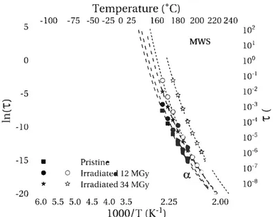
Fig. 7. Arrhenius diagram of relaxation times associated with dielectric phenomena observed in PEEK samples. Full symbols represent room temperature irradiated samples while empty symbols represent 165°( irradiated samples.
Table2
Fit parameters obtained for dipolar relaxations and fragility indexes m ofpristine, room temperature irradiated and 165"C irradiated PEEK samples. y relaxation l'.X relaxation 'îo,a àH (s) (kj.mol-1) Pristine 1.lxl0-15 49.0 KT Irradiation Dose= 12 MGy 1.9x10⁻¹⁵ 48.0 Dose-34MGy 9.6x10⁻¹⁶ 49.6 165"C Irradiation Dose-12 MGy 3.3x10⁻¹⁵ 46.5 Dose= 34MGy 1.4x10⁻¹⁵ 48.6
linking and amorphisation.
3.4. Study of dielectric relaxations
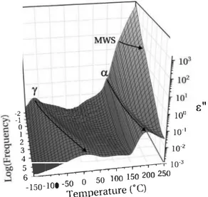
The dielectric Joss permittivity e" of a pristine sample is pre sented in Fig. 6 as a function of frequency and temperature.
Three dielectric phenomena can be observed. The y and rJ. re laxations are consistent with relaxations observed by mechanical analyses. In addition, at low frequency and high temperature, a third dielectric phenomenon can be guessed but it is hidden by the predominance of conductivity. This last phenomenon has been associated with a Maxwell-Wagner-Sillars (MWS) polarisation [36]. It corresponds to the interfacial polarisation of crystallite induced by the dilference of conductivity between crystalline and amor phous phases. In order to fit this last phenomenon with equation
( 6), it was necessary to remove the conductivity contribution by recalculating the Joss permittivity from the derivative of storage permittivity [37].
For each of these relaxation phenomena, equation (6) was used to extract the associated relaxation times. They are plotted as a function of 1000/T for each dose and irradiation temperature in
't"o,v ŒJ T� m (s)
cc-
1) ("C) 4.2x10⁻¹⁷ 4.42xrn-• 90 127 4.Sxlo-17 4.50x10⁻⁴ 94 128 6.2x10⁻¹⁷ 4.SSxl0-4 98 133 6.3x10⁻¹⁸ 4.12x10⁻⁴ 99 165 4.8x10⁻¹⁸ 3.69x10⁻⁴ 102 172Fig. 7. As expected, the sub-glass relaxation y follows an Arrhenius behaviour while the rJ. relaxation can be fitted with a VTF behaviour law. Curves resulting from these lits are represented in dashed lines and fit parameters are reported in Table 2. For the rJ. relaxation, the fragility index m has been calculated with the following equation [38]:
(d log(r))
m = d (Tg/T) T-T, (12) In this equation, the Tg value for the second heating run is used
in order to prevent the elfect of internai stresses.
For the y relaxation, the value of 49 kJ m□1-1 for 6-H is consistent with the literature [39,40].
For the rJ. relaxation, as predicted by the VTF theory, the value of T00 = Tg - so·c confirms its attribution to the dielectric manifes
tation of the glass transition. The fragility index values reported in the literature lie between 150 and 280, depending on the analysis method and on the material state [41,42]. In this study, a value of 127 was calculated for pristine PEEK which is in the same order of magnitude as literature values.
Finally, the MWS relaxation times can be fitted by a VTF
behaviour law. It indicates that this dielectric process is governed by the amorphous phase mobility.
3.4.1. y relaxation
This relaxation is not affected at ail by the sample ageing, whether after room temperature irradiations or 165 ° C irradiations.
Like for mechanical analysis results, it indicates that the cross linking of the amorphous phase is not sufficiently dense to modify the localised mobility response.
3.4.2. et: relaxation
For this relaxation, Fig. 7 shows a shift of characteristic times to higher temperatures after irradiation. Like for thermal and me chanical analyses, it indicates an increase in the thermal activation of glass transition. It is due to the cross-linking of amorphous phase which limits the macromolecule mobility. This can be view as well from the point of view of relaxation times: after irradiation, the a relaxation is shifted to longer times which is consistent with a slower relaxation kinetic. Between room temperature and 165 °C
irradiations, a greater shift is observed with increasing irradiation temperature which further confirms the higher density of cross links induced by irradiation above glass transition. This a relaxa tion dynamic slow-down with an increasing cross-link density has already been observed for different polymer systems [43.44]. Moreover, Kramarenko et al. observed an increase in fragility index with cross-link density [44]. In this work, fragility index increases as well with ionising dose. However, room temperature irradiated samples show a moderate increase in contrast to 165 °C irradiated
samples. Therefore, this higher increase in m is consistent with a higher cross-linking density.
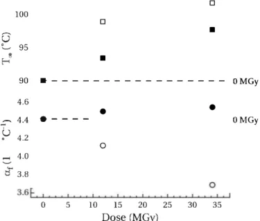
This shift to higher temperatures can also be noticed through the evolution ofT 00 which is represented, as well as the evolution of
af, in Fig. 8 versus ionising dose. Indeed, an increase in T00 value is
observed with an increasing dose which is consistent with the
100
□
û
0 95 '-' 8■
E-<increase in Tg observed by DSC and in Ta by DMA. These data also
confirm the faster ageing induced by high-temperature irradiations with a faster increase in T 00•
For the af parameter, opposite evolutions are observed between both irradiation temperatures. Like for the evolutions of diffusion kinetics and a relaxation area, these opposite tendencies can be link to the competition between amorphisation and cross-linking. For room temperature irradiated samples, the slight increase in af is linked to the predominant influence of amorphisation. Since this parameter is associated with the free volume expansion coefficient, less crystallites induce less stresses on the amorphous phase and therefore Iead to a higher expansion coefficient. Nonetheiess, this effect is probably partially balanced by the cross-linking of amor phous phase which limits its mobility and consequently its possible expansion. In 165°C irradiated samples, DSC analyses showed an
equivalent amorphisation of the polymer white the density of cross-linking increases faster with ionising dose. Thus, it is assumed that the cross-linking influence becomes predominant in front of amorphisation and induces a af decrease.
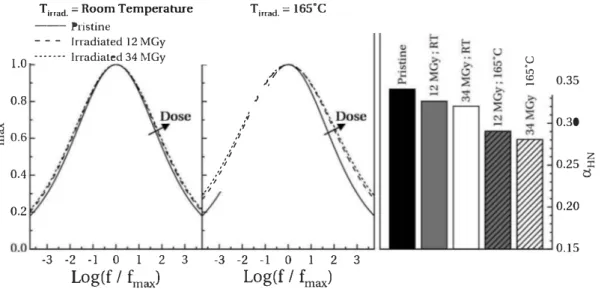
Finally, the study of the a relaxation loss permittivity peak width can also provide information about the environment close to relaxing entities [2]. In this way, the Ioss perrnittivity peaks have been recalculated for each type of samples using the imaginary part of equation (6), which is developed in Ref. [21 ], and the Havriliak Negami parameters obtained by the fit of a relaxation. This method allows us to eliminate the conductivity in order to better discern any change. The data have been norrnalised on position and amplitude to compare the width evolution at one isotherrn and for different samples. The resuiting curves, calculated at 180°C, are
represented in Fig. 9 as well as the value of aHN parameter which governs the peak width.
The graph shows a broadening of the a relaxation with increasing dose, either after room temperature or 165°C irradia
tions. These evoiutions are confirmed by the decrease in aHN
observed on the histogram. In the dieiectric relaxation theory, this
□
■
90 ■ - - - 0 MGy 4.6 � 4.4 e-u
0 4.2 ,.... 4.0 '-'6
3.8 0 5•
0 10 15 20 25Dose (MGy)
•
OMGy 30 35T,rrad. = Room Temperature Ti_rrad. = 165"C 1.0 0.8 � 6 0.6 0.4 0.2 --- Pristine - - - lrradiated 12 MGy · · · ·· 1 rractiated 34 MGy
.•
.•
,1 ,1,.,
,.,
,'I ,'I ,� J ,,; ,Ju
U') (0 ,... 0.35 0.30 0.25} 0.20 0.15 -3 -2 -1 0 1 2 3 Log(f / fmaJ -3 -2 -1 0 1 2 3 Log(f / fmruJFig. 9. Normalised loss permittivity peak for a. relaxation at a temperature of 180"C (left graphs) and value of a;HN parameter at the same temperature (right graph).
broadening is associated with an increase in the relaxation time distribution. In the case of the a relaxation, this wider distribution can be linked to a more heterogeneous environment in the vicinity of relaxing entities, i.e. a more heterogeneous amorphous phase. This heterogeneity increase is associated with the creation of cross linking nodes in this phase. This figure also shows a greater het erogeneity increase for 165 • C than for room temperature irradiated samples which is the consequence of a higher cross-linking density as assumed above.
3.4.3. MWS relaxation
Fig. 7 shows no evolution of MWS relaxation times after irra diation at room temperature but a shift to higher temperature (longer relaxation times) once irradiated at 165°C. It is known that
the relaxation times of a MWS process is proportional to the storage
...
35...
�...
30 �...
...
1.0 25J
0.9 0.8Fig. 10. Value of �HN parameter at 230'C (bars) obtained for MWS mode and crys tallinity ratio 'X.c (symbols) obtained from DSC analyses.
permittivity e' of the two phases (i.e. crystalline and amorphous) and inversely proportional to their electrical conductivity [20, p. 498]. The e' value is dependent from the dipole density which is not modified by irradiation. Thus, the relaxation time shift can be associated with a conductivity decrease of one of them. As crystal conductivity remains stable after irradiation, this shift to longer relaxation times can indicate that irradiation at 165 • C decreases the amorphous phase conductivity. This conductivity evolution can be associated with the increase in defects (cross-links) which limits the mobility of electrical charges in the amorphous phase. For room temperature irradiated samples, this decrease is probably also present but less significant due to the lower cross-linking density. Moreover, it can be assumed that the increase in MWS relaxation times is compensated by the decrease in crystallite size, i.e. crys tallites being smaller, their polarisation occurs at higher fre quencies/shorter times.
Like for a relaxation, aHN parameter can give some information
on the homogeneity in the vicinity of relaxing entities. Fig. 10 presents the value of this parameter at 230°C for each sample.
Crystallinity ratios obtained by DSC analyses are reported as well on the same figure .
For room temperature irradiated samples, the value of aHN de
creases with increasing ionising dose as well as the crystallinity ratio. It can be assumed that by decreasing crystallite size ( associ ated with the decrease in Tm), irradiations also increase their size
distribution and lead to a wider distribution of relaxation times. After irradiations at 165°C, 12 MGy irradiated sample follows the
same behaviour with a aHN and Xe decrease. However, for 34 MGy,
the decrease in homogeneity ( i.e. in aHN) is significantly lower
compared to the decrease in crystallinity ratio. It has been shown in previous studies that polymers of PolyArylEtherKetone family are subject to secondary crystallisation phenomenon; this phenome non occurs at a temperature between glass transition and melting thanks to the higher mobility of amorphous phase [ 45,46]. Thus, it can be assumed that this phenomenon promotes a reorganisation at the edge of crystallites during irradiation and leads to a crys talline phase homogenisation.
4. Conclusion
The influence of irradiation temperature on radiative ageing of PolyEtherEtherKetone by electronic irradiations has been studied. For this purpose, two irradiation campaigns have been carried out in the SIRENE facility installed at the ONERA: the first was per formed at room temperature and the second at 165 "C, just above the PEEK glass transition temperature. For each irradiation tem perature, two average ionising doses were deposited: 1.2x 10⁷ Gy
and 3.4x10⁷ Gy. Thanks to the high energy of electrons (350 keV),
these doses are homogeneous over sample thickness.
DSC analyses showed a real influence of the temperature on the ageing kinetics. In the amorphous phase, a faster increase in Tg with
dose was observed. It was associated with a higher cross-linking density due to a faster recombination rate of radicals above glass transition. In the crystalline phase, the increase in irradiation tempe rature only affects the evolution of Tm white the amorph isation of samples remains similar. It was associated with the fact that at 165 "C, only the mobility of amorphous phase is impacted.
These assumptions on the influence of irradiation temperature on the physico-chemical ageing were then studied and corrobo rated by using different probes: molecular (i.e. acetone diffusion), mechanical and dielectric probes.
• The higher cross-linking density in 165 ·c irradiated samples has been confirmed by slower diffusion kinetics, a higher increase in rubber modulus and a shift of rJ. relaxation times to higher
temperatures. Moreover, the study of the rJ. relaxation peak
width showed that 165 ·c irradiations induce a more heteroge neous medium in the vicinity of relaxing entities associated with the higher cross-linking density. Nonetheless, no evolution of y relaxation times was observed and suggests that cross linking density remains too low to modify localised macro molecules dynamics.
• The crystalline phase ageing was studied through the MWS relaxation. The comparison of crystallinity ratio with rJ.HN values showed that room temperature irradiations increase the het erogeneity of crystalline phase proportionally to the decrease in crystallinity ratio. Nonetheless, maintaining samples above glass transition during 165 "C irradiations looks to homogenise crystalline phase.
• Finally, it has been shown that the competition between amorphisation and cross-linking density has a significant in fluence on the polymer behaviour after irradiations.
CRediT authorship contribution statement
G. Rival: Conceptualization, Methodology, Validation, Investiga tion, Writing - original draft, Visualization. E. Dantras: Conceptual ization, Methodology, Validation, Investigation, Writing - review & editing, Supervision. T. Paulmier: Conceptualization, Methodology, Validation, Investigation, Writing - review & editing, Supervision. Declaration of competing interest
The authors declare that they have no known competing financial interests or persona! relationships that could have appeared to influence the work reported in this paper.
Acknowledgement
The authors would like to thank the CNES for technical support (funding of the SIRENE facility) and the Région Occitanie for financial support in this project.
References
[li RD. Leach. Failures and Anomalies Attributed to Spacecraft Charging. Tech. Rep. Tech. Rep. NASA-RP-1375, NASA Marshall Space Flight Center, 1995.
[2] A. Roggero, E. Dantras, T. Paulmier, C. Tonon, S. Lewandowski, S. Dagras, D. Payan, Dynamic glass transition of filled polysiloxane upon electron irra
diation, J. Non-Cryst. Solids 455 (2017) 17-23, https:lfdoi.org/10.1016/ j.jnoncrysol.2016.10.025.
[3] A. Roggero, E. Dantras, T. Paulmier, C. Tenon, S. Dagras, S. Lewandowski, D. Payan, Inorganic fillers influence on the radiation-induced ageing of a space-used silicone elastomer, Polym. Degrad. Stabil. 128 (2016) 126-133, https://doi.org/10.1016/j.polymdegradstab.2016.03.010.
[4] R. Hanna, T. Paulmier, P. Molinie, M. Belhaj, B. Dirassen, D. Payan, N. Balcon, Radiation induced conductivity in space dielectric materials, j. Appl. Phys. 115
(2014). 033713, https:lfdoi.org/10.1063/1.4862741.
[5] T. Paulmier, B. Dirassen, M. Belhaj, D. Rodgers, Charging properties of space
used dielectric materials, IEEE Trans. Plasma Sei. 43 (2015) 2894-2900,
https://doi.org/10.1109/TPS.2015.2453012.
[6] J. Sun, Y. Zhang, X. Zhong, X. Zhu, Modification of polytetrafluoroethylene by radiation--1. Improvement in high temperature properties and radiation
stability. Radial. Phys. Chem. 44 (1994) 655-659, https:lfdoi.org/10.1016/ 0969-806)((94)90226-7.
[7] J. Li, A. Oshima, T. Miura, M. Washio, Preparation of the crosslinked poly ethersulfone films by high-temperature electron-beam irradiation, Polym.
Degrad. Stabil. 91 (2006) 2867-2873, https:lfdoi.org/10.1016/ j.polymdegradstab.2006.09.005.
[8] M. Ferry, E. Bessy, H. Harris, P.J. Lutz, J.-M. Ramillon, Y. Ngono-Ravache, E. Balanzat, Aliphatic/aromatic systems under irradiation: influence of the irradiation temperature and of the molecular organization, J. Phys. Chem. B
117 (2013) 14497-14508, https:lfdoi.org/10.1021/jp406260z.
[9] H. Kudoh, N. Kasai, T. Sasuga, T. Seguchi, Low temperature gamma-ray irra diation effects of polymer materials on mechanical property, Radiat. Phys.
Chem. 43 (1994) 329-334, https:lfdoi.org/10.1016/0969-806X(94)90021-3.
[10) M. Mélot, Y. Ngono-Ravache, E. Balanzat, Very low temperature irradiation of aliphatic polymers: role of radical migration on the creation of stable groups
(0-127), Nue!. lnstrum. Methods B 208 (2003) 345-352, https:lfdoi.org/ 10.1016/S0168-583X(03 )00892-9.
[11) A. Oshima, Y. Tabata, H. Kudoh, T. Seguchi, Radiation induced crosslinking of
polytetrafluoroethylene, Radial. Phys. Chem. 45 (1995) 269-273. https:// doi.org/10.1016/0969-806X(94)E0009-8.
[12) Y. Tabata, A. Oshima, K. Takashika, T. Seguchi, Temperature effects on radia tion induced phenomena in polymers, Radiat. Phys. Chem. 48 (1996)
563-568, https://doi.org/10.1016/0969-806X(96)00081-3.
[13[ A.-M. Lanouette. M.-J. Potvin. F. Martin. D. Houle, D. Therriault, Residual
mechanical properties of a carbon fibers/PEEI< space robotic arm after simu
lated orbital debris impact. lnt. J. Impact Eng. 84 (2015) 78-87, https:// doi.org/10.1016/j.ijimpeng.2015.05.01 O.
[14) S.D. Baie, K. Goetz, P.R. Harvey, P. Turin, J.W. Bonneil, T. Dudok de Wit,
RE. Ergun, RJ. MacDowall, M. Pulupa, M. Andre, M. Bolton, J.-L Bougeret,
T.A. Bowen, D. Burgess, C.A. Cattell, B.D.G. Chandran, C.C. Chaston, C.H.K. Chen, M.K. Choi, J.E. Connemey, S. Cranmer, M. Diaz-Aguado, W. Donakowski, J.F. Drake, W.M. Farrell, P. Fergeau, J. Fermin, J. Fischer, N. Fox, D. Glaser, M. Goldstein, D. Gordon, E. Hanson, S.E. Harris, L.M. Hayes, J.J. Hinze, J.V. Hollweg, T.S. Horbury, R.A. Howard, V. Hoxie, G. Jannet, M. Karlsson, J.C. Kasper, P.J. Kellogg, M. Kien, J.A. Klimchuk, V.V. Krasnoselskikh, S. Krucker, J.J. Lynch, M. Maksimovic, D.M. Malaspina, S. Marker, P. Martin, J. Martinez
Oliveros. J. McCauley, D.J. McComas, T. McDonald, N. Meyer-Vernet,
M. Moncuquet, S.J. Manson, F.S. Mozer, S.D. Murphy, J. Odom, R. Oliverson,
j. Oison, E.N. Parker, D. Pankow, T. Phan, E. Quataert. T. Quinn. S.W. Ruplin,
C. Salem, D. Seitz, D.A. Sheppard, A. Siy, K. Stevens, D. Summers, A. Szabo,
M. Timofeeva. A. Vaivads. M. Velli. A. Yehle, D. Werthimer, J.R. Wygant, The
FIELDS instrument suite for solar probe plus: measuring the coronal plasma and magnetic field, plasma waves and turbulence, and radio signatures of
solar transients. Space Sei. Rev. 204 (2016) 49-82. https:lfdoi.org/10.1007/ sl 1214-016-0244-5.
[15) G. Rival, T. Paulmier, E. Dantras, Influence of electronic irradiations on the chemical and structural properties of PEEK for space applications, Polym.
Degrad. Stabil. 168 (2019), 108943, https:lfdoi.org/10.1016/ j.polymdegradstab.2019.108943.
[16[ L Yang, Y. Ohki, N. Hirai, S. Hanada, Aging of poly(ether ether ketone) by heat
and gamma rays -- its degradation mechanism and effects on mechanical, dielectric and thermal properties, Polym. Degrad. Stabil. 142 (2017) 117-128, https://doi.org/10.1 Ol 6/j.polymdegradstab.2017.06.002.
[17[ D.J. Blundell, B.N. Osborn, The morphology of poly(aryl-ether-ether-ketone), Polymer 24 (1983) 953-958, https:lfdoi.org/10.1016/0032-3861(83)90144-l.
[18) EJ. Stober, J.C. Seferis, Fluid sorption characterization of PEEK matrices and
composites, Polym. Eng. Sei. 28 (1988) 634-639, https://doi.org/10.1002/ pen.760280912.
[19) G. Mensitieri, A. Apicella, j.M. Kenny, L Nicolais, Water sorption kinetics in
poly(aryl ether ether ketone). J. Appl. Polym. Sei. 37 (1989) 381-392. https:// doi.org/10.1002/app.1989.070370207.
[20) F. Kremer, A. Schônhals, Broadband Dielectric Spectroscopy, Springer, Berlin,
2003.
polymer systems, J. Polym. Sei., Polym. Symp. 14 (1966) 99-117, https:// doi.org/10.1002/polc.5070140111.
[22] S. Havriliak, S. Negami, A complex plane representation of dielectric and mechanical relaxation processes in some polymers, Polymer 8 (1967) 161-210, https://doi.org/10.1016/0032-3861 (67)90021-3.
[23] H. Vogel, The law of the relation between the viscosity of liquids and the temperature, Phys. Z. 22 (1921) 645-646.
[24] G.S. Fulcher, Analysis of recent measurements of the viscosity of glasses,J. Am. Ceram. Soc. 8 (1925) 339-355, https:lfdoi.org/10.1111/j.1151-2916.1925.tbl6731.x.
[25] G. Tammann, W. Hesse, Die Abhângigkeit der Viscositiit von der Temperatur bie unterkühlten Flüssigkeiten, Z. Anorg. Allg. Chem. 156 (1926) 245-257,
https://doi.org/10.1002/zaac.19261560121.
[26] S.Z.D. Cheng, M.Y. Cao, B. Wunderlich, Glass transition and melting behavior of poly( oxy-1,4-phenyleneoxy-1,4-phenylenecarbonyl-1,4-phenylene) (PEEK), Macromolecules 19 (1986) 1868-1876, https:lfdoi.org/10.1021/ ma00161a015.
[27] O. Yoda, The crystallite size and lattice-distortions in the chain direction of irradiated poly (aryl-Ether-Ketone), Polym. Commun. 26 (1985) 16-19. [28] E. Bagley, F.A. Long, Two-stage sorption and desorption of organic vapors in
cellulose acetate, J. Am. Chem. Soc. 77 (1955) 2172-2178, https:lfdoi.org/ 10.1021 /jaOl 613a038.
[29] W.K. Loh, A.D. Crocombe, M.M. Abdel Wahab, I.A. Ashcroft, Modelling anomalous moisture uptake, swelling and thermal characteristics of a rubber toughened epoxy adhesive, !nt. j. Adhesion Adhes. 25 (2005) 1-12, https:// doi.org/10.1016/j.ijadhadh.2004.02.002.
[30] L Perrin, Q.T. Nguyen, R. Clement, J. Neel, Sorption and diffusion of solvent vapours in poly(vinylalcohol) membranes of different crystallinity degrees, Polym. !nt. 39 (1996), https:lfdoi.org/l0.1002/(SICI)I097-0126(199603)39: 3<251: :AID-Pl496>3.0.C0;2-W.
[31] K.F. Chou, S. Lee, C.C. Han, Water transport in crosslinked 2-hydroxyethyl methacrylate, Polym. Eng. Sei. 40 (2000), https:lfdoi.org/10.1002/pen.11228. [32] J.E. Harris, L.M. Robeson, Miscible blends of poly(aryl ether ketone)s and po!yetherimides, J. Appl. Polym. Sei. 35 (1988) 1877-1891, https:lfdoi.org/ 10.1002/app.1988.070350713.
[33] M. Coulson, L. Quiroga Cortés, E. Dantras, A. Lonjon, C. Lacabanne, Dynamic rheological behavior of poly( ether ketone ketone) from solid state to melt state, J. Appl. Polym. Sei. 135 (2018), 46456, https:lfdoi.org/10.1002/ app.46456.
[34] J.D. Ferry, Viscoelastic Properries of Polymers, third ed., Wiley, 1980.
[35] M. Doi, S.F. Edwards, The Theory of Polymer Dynamics, vol.73, oxford uni versity press, 1988.
[36] G. Perrier, Maxwell-Wagner-Sillars relaxations and crystallinity in PEEK, Compos. lnterfac. 4 (1996) 111-117, https:lfdoi.org/10.1163/ 156855496X00191.
[37] M. Wübbenhorst, J. van Turnhout, Analysis of complex dielectric spectra. I. One-dimensional derivative techniques and three-dimensional modelling, J. Non-Cryst. Solids 305 (2002) 40-49,
https:lfdoi.org/10.1016/S0022-3093(02)01086-4.
[38] R. Bohmer, K.L Ngai, C.A. Angell, D.J. Plazek, Nonexponential relaxations in strong and fragile glass formers, J. Chem. Phys. 99 (1993) 4201-4209, https:// doi.org/10.1063/1.466117.
[39] M. Mourgues-Martin, A. Bernés, C. Lacabanne, Dielectric relaxation phenom ena in PEEK, Thermochim. Acta 226 (1993) 7-14, https:lfdoi.org/10.1016/ 0040-6031(93)80201-K.
[40] J. Audoit, L Rivière,J. Dandurand, A. Lonjon, E. Dantras, C. Lacabanne, Thermal, mechanical and dielectric behaviour of poly( aryl ether ketone) with low melting temperature,J. Therm. Anal. Calorim. 135 (2018) 2147-2157, https:// doi.org/10.1007 /si 0973-018-7292-x.
[41] A.G. Al Lafi, Structural development in ion-irradiated poly(ether ether ketone) as studied by dielectric relaxation spectroscopy, j. Appl. Polym. Sei. 131 (2014), https://doi.org/10.1002/app.39929.
[42] N.D. Govinna, T. Keller, C. Schick, P. Cebe, Melt-electrospinning ofpoly(ether ether ketone) fibers to avoid sulfonation, Polymer 171 (2019) 50-57, https:// doi.org/10.1016/j.polymer.2019.03.041.
[43] J.K.W. Glatz-Reichenbach, L. Sorriero, J.J. Fitzgerald, Influence of crosslinking on the molecular relaxation of an amorphous copolymer near its glass transition temperature, Macromolecules 27 (1994) 1338-1343. [44] V.Y. Kramarenko, T.A. Ezquerra, I. Sics, F.J. Balt.i-Calleja, V.P. Privalko, Influence
of cross-linking on the segmental dynamics in model polymer networks, J. Chem. Phys. 113 (2000) 447-452.
[45] H. Marand, A. Prasad, On the observation of a new morphology in poly( arylene ether ether ketone ). A further examination of the double endothermic behavior of poly(arylene ether ether ketone), Macromolecules 25 (1992) 1731-1736, https:lfdoi.org/10.1021/ma00032a017.
[46] L Quiroga Cortés, N. Caussé, E. Dantras, A. Lonjon, C. Lacabanne, Morphology and dynamical mechanical properties of poly ether ketone ketone (PEKK) with meta phenyl links,). Appl. Polym. Sei. 133 (2016), 43396, https:lfdoi.org/ 10.1002/app.43396.