OATAO is an open access repository that collects the work of Toulouse
researchers and makes it freely available over the web where possible
Any correspondence concerning this service should be sent
to the repository administrator:
[email protected]
This is an author’s version published in:
http://oatao.univ-toulouse.fr/24320
To cite this version:
Rival, Guilhem
and Paulmier, Thierry and Dantras, Eric
Influence of electronic
irradiations on the chemical and structural properties of PEEK for space
applications. (2019) Polymer Degradation and Stability, 168. 1-8. ISSN 0141-3910
Influence of electronic irradiations on the chemical and structural
properties of PEEK for space applications
G. Rival
a,b, T. Paulmier
a, E. Dantras
b,*aONERA - DPHY, The French Aerospace Lab, F-31055, Toulouse, France
bCIRIMAT - Universit!e Toulouse III Paul Sabatier, Physique des Polym"eres, 118 route de Narbonne, 31062, Toulouse, France
a r t i c l e
i n f o
Keywords:
Dynamic mechanical analysis Ionising radiations PEEK
Thermal analysis Thermoplastic polymer
a b s t r a c t
Polymer materials used in satellite manufacturing are exposed to severe environmental conditions. Irradiation by high-energy electrons induces chemical modifications of macromolecules. Poly-EtherEtherKetone (PEEK) is used in space industry and therefore, its behaviour regarding electronic ir-radiations has to be studied. Thus, the aim of this work is to investigate the effect of experimental electronic irradiations on the physical and chemical structure of PEEK. In this way, PEEK films were irradiated under high vacuum by a mono-energetic electron beam. Doses deposited are representatives of 15 years in geostationary electronic environment. The study of irradiated samples revealed modifi-cations of the chemical and physical structures. Irradiation predominantly induces cross-linking phe-nomena in the amorphous phase in front of chain scission phephe-nomena. Irradiation also leads to a decrease in crystallite size and crystallinity ratio.
1. Introduction
In Geostationary Earth Orbit (GEO) environment, satellites’ materials are subject to several constraints like micrometeorites, space debris impacts, thermal cycling and irradiations by energetic particles (neutrons, protons, electrons…). In the case of polymer materials, electronic irradiations are responsible for two major is-sues: charge phenomena and physico-chemical ageing. Since polymer materials are electrical insulators, low-energy electrons are accumulated on their surface. This accumulation leads to an increase in surface electric potential and therefore to electrostatic discharge phenomena which are at the origin of many spacecraft failures [1]. Moreover, irradiation by high-energy electrons induces modifications of the polymer physico-chemical structure which leads to evolution of its initial properties. These phenomena have already been investigated in several studies like Roggero et al. who studied the effect of electronic irradiation on a space-used silicone elastomer [2,3].
PolyEtherEtherKetone (PEEK) is a high performance polymer which is increasingly used for structural application in satellite manufacturing. Because of these new uses, it becomes necessary to
investigate PEEK behaviour towards electronic irradiations. Since its first commercialisation by Imperial Chemical Industries in 1978, numerous studies have focused on the behaviour of PEEK and its composites under different radiation sources like gamma rays [4,5], ultraviolet light [6] or under combined ageing [7,8]. In the specific case of electronic irradiations, Sasuga et al. studied the mechanical behaviour evolution of irradiated samples [9,10]. They observed an overall deterioration of tensile properties, amplified in amorphous samples, and an increase in the viscoelastic transition temperature associated with reticulation of amorphous phase. This increase is observed as well by dielectric measurements which also brought into evidence a wider relaxation time distribution [11]. More recently, Kornacka et al. investigated the effect of electronic irra-diations on PEEK in order to identify radical compounds formed during ageing [12]. They also observed a decrease in thermal sta-bility. However, they did not show any evolution of Differential Scanning Calorimetry thermograms probably because of the very low dose deposited in their samples.
This paper aims to determine, through various experimental analyses, the influence of electronic irradiations on the physical and chemical structures of PolyEtherEtherKetone. All previous studies were carried out in an oxidative atmosphere which is not repre-sentative of space environment. In that way, PEEK samples were irradiated by an electron beam at room temperature but most importantly under high vacuum in order to better represent
* Corresponding author.
E-mail address:[email protected](E. Dantras).
satellite environment. Moreover, the doses deposited in samples for this study are representatives of satellite lifetime and of geosta-tionary electronic environment.
2. Materials and methods
2.1. Material
For this study, two types of PEEK films have been used: first one is a high-crystallinity sample of 100
m
m in thickness and second one is a low-crystallinity sample with a thickness of 75m
m. The crystallinity ratio of pristine samples have been determined in both cases by Differential Scanning Calorimetry and obtained values are reported inTable 1.2.2. Experimental simulation of the space environment
To simulate the effects of electronic radiations, samples have been exposed at room temperature and under high vacuum to a mono-energetic electron beam of 350 keV, thanks to SIRENE facility (ONERA, Toulouse, France). Three experimental irradiation cam-paigns have been carried out. The resulting doses are: 1.2 ! 107Gy and 3.4 ! 107Gy for high-crystallinity samples, 1.4 ! 107Gy for low-crystallinity samples. They were achieved in less than 60 h thanks to the high beam currents (up to 60 nA.cm"2), which represents an average dose rate of 250 Gy.s"1in these conditions and for this
material. In the case of low-crystallinity samples, irradiations have been achieved in order to evaluate the influence of the polymer physical structure. Thus, doses higher than 1.4 ! 107Gy were not necessary: this first dose level were sufficient to already notice differences.
These experimental doses D have been calculated using equa-tion(1). D!Gy ¼ J:kg"1"¼ 1:6 10"9!
F
1r
#dE dx $ (1)Where
F
is the total fluence applied during irradiation (cm"2),r
thematerial density (g.cm"3) and dE =dx the stopping power
(keV.
m
m"1). This last quantity is defined as the energy lost per unitlength by an incident particle passing through a medium. It de-pends mainly on medium density, its atomic composition and incident particles energy. When normalised by density, it is referred to a mass stopping power usually expressed in MeV.cm2.g"1.
For this study, electronic stopping power of PEEK was estimated by using the open-source software CASINO (“monte CArlo SImu-lation of electroN trajectory in sOlids”) [13,14]. This software allows performing Monte-Carlo simulations of electron interactions with a system of solids defined by their chemical composition and density. For the sake of simplicity, PEEK was modelled by a carbon solid
with a density of 1.3 g.cm"3given by the supplier. Thus, stopping powers resulting from the irradiation by 350 keV electrons were simulated for experimental conditions. Corresponding dose depth profiles, calculated by equation(1), are represented by dashed lines inFig. 1.
To compare with these experimental profiles, dose deposited by geostationary electronic environment have been calculated as well. For this purpose, the geostationary electron model IGE-2006 was used as basis for calculation [15]. This model gives the energy distribution of electronfluxes 4 (keV"1.cm"2.s"1.sr"1) in geosta-tionary orbit. Thus, CASINO simulations of stopping power were performed by varying electron energy over the range [1 keV; 1 MeV]. In addition, a log-log interpolation of the IGE data was made in order to have a higher number of (E, 4) coordinates. Using these simulated data, omnidirectional dose rates (Gy.s"1. sr"1) were
calculated for each micrometers of sample by integrating over en-ergy the product of flux 4 and mass stopping power. Considering the exposure of a planar surface, dose rate (Gy.s"1) was obtained by
multiplying by a factor 2
p
corresponding to the solid half-angle. Finally, doses D are deduced by multiplying dose rate and expo-sure time. They are represented by solid lines for 1, 5 and 15 years in Fig. 1.Fig. 1shows an homogeneous experimental energy deposition in sample with a ratio between back and front face close to 1.5. This homogeneity is permitted by the high-energy beam which goes through samples without inducing electron implantation. In the case of simulated electronic geostationary environment, profiles show an heterogeneous dose deposition over the sample thickness induced by the distribution of fluxes as described by IGE-2006 model.
According to these simulated data, experimental doses corre-spond to 15 years of exposure in GEO at a depth of 37
m
m (D ¼ 1.2 ! 107Gy), 27m
m (D ¼ 1.4 ! 107Gy) and 17m
m (D ¼ 3.4 ! 107Gy), denoting an acceleration factor higher than 1000 in both cases.2.3. ThermoGravimetric analysis
In order to investigate evolutions of the polymer thermal sta-bility after irradiation, ThermoGravimetric Analyses (TGA) were performed on a Q50 device from TA Instruments. Samples, placed in oxidising atmosphere (synthetic air) or inert atmosphere (ni-trogen), were heated from room temperature to 900$C at a rate of
20$C.min"1.
2.4. Differential Scanning Calorimetry
For this study, Differential Scanning Calorimetry (DSC) ther-mograms were carried out on a DSC 7 manufactured by Perki-nElmer. Samples were directly cut from virgin and irradiated sheets for a total analysed mass between 5 and 15 mg. Analysis, carried out under nitrogen flow, consists of two heating runs and one cooling
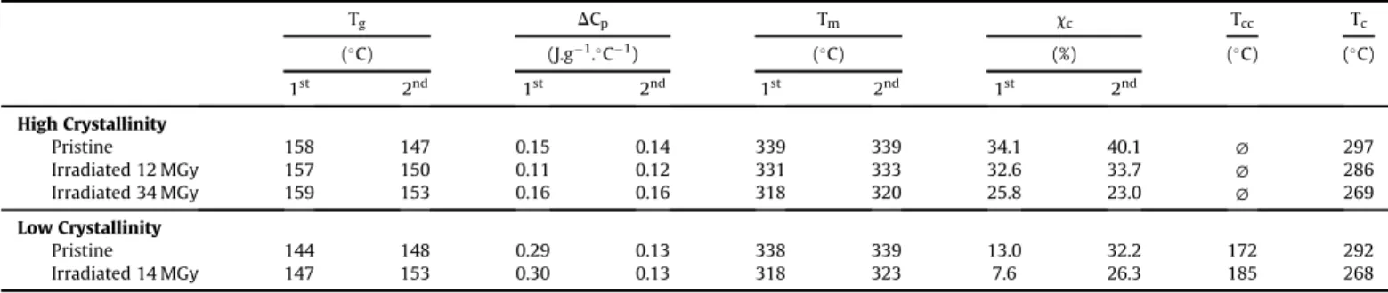
Table 1
Transitions temperatures, heat capacity jumps and crystallinity ratios of samples as a function of doses. 1strefers to first heating runs and 2ndto second heating runs.
Tg DCp Tm cc Tcc Tc ($C) (J.g"1.$C"1) ($C) (%) ($C) ($C) 1st 2nd 1st 2nd 1st 2nd 1st 2nd High Crystallinity Pristine 158 147 0.15 0.14 339 339 34.1 40.1 ∅ 297 Irradiated 12 MGy 157 150 0.11 0.12 331 333 32.6 33.7 ∅ 286 Irradiated 34 MGy 159 153 0.16 0.16 318 320 25.8 23.0 ∅ 269 Low Crystallinity Pristine 144 148 0.29 0.13 338 339 13.0 32.2 172 292 Irradiated 14 MGy 147 153 0.30 0.13 318 323 7.6 26.3 185 268
run between 50$C and 400$C at a constant rate of 10$C.min"1. First
order transition temperatures are taken at the maximum of the peak while the glass transition temperatures Tgare determined by
the tangent method as well as the heat capacity jumps
D
Cp.Crys-tallinity ratio
c
cof samples was calculated from melting and cold crystallisation enthalpies using equation(2).c
c¼D
Hm"D
HccD
H∞! 100 (2)
Where
D
Hmis the sample melt enthalpy (J.g"1),D
Hcc is the cold crystallisation enthalpy (J.g"1) andD
H∞ is the theoretical melt
enthalpy of a fully crystalline sample determined for PEEK at 130 J.g"1[16].
2.5. Acetone absorption test
To investigate the effect of structural evolution induced by ir-radiations, acetone (selected penetrant) absorption tests were performed on pristine and irradiated PEEK samples. In the case of using water as penetrant, only a small amount can be absorbed by PEEK (in the order of 0.5 %m[17,18]) which leads to greater
mea-surement uncertainties. For acetone, Stober and Seferis reported a weight gain of about 7 %mallowing to minimise uncertainties [19].
Experimentally, samples were dried in a desiccator (under vacuum and with silica gel) during 1 week. Thereafter, they were weighed in order to determine their initial dried mass noted m0
and then immersed in an acetone bath maintained at room tem-perature. To carry out the weighing, samples are taken out of the bath, quickly dried with absorbent paper, weighed on a precision balance and then immersed again in acetone. The weight gain (WG) is then calculated by equation(3).
WG ¼m " m0
m0 ! 100
(3)
However, it is well known that due to the density and the low mobility of crystalline phase, absorption phenomena in polymer take place in the amorphous phase. Therefore, in order to take into account a possible crystallinity ratio evolution in irradiated sam-ples, the weight gain will be normalised by the quantity of amor-phous phase. The normalised weight gain (NWG) is then calculated
with equation(4).
NWG ¼ m " m0
ð1 "
c
c=100Þ ! m0! 100 (4)
Where
c
cis the crystallinity ratio (%) calculated from Differential Scanning Calorimetry analyses.2.6. Dynamic Mechanical Analysis
Dynamic Mechanical Analysis (DMA) tests presented in this study were performed on an ARES G2 strain-controlled rheometer from TA Instruments. Sample dimensions are 35 mm ! 12.5 mm. Due to their thickness, PEEK films were analysed in tensile geom-etry mode to ensure a good signal-to-noise ratio. For each sample, heating runs are performed over the temperature range [-130$C;
220$C] at a heating rate of 3$C.min"1. In order to stay within the
material linearity range, strain and frequency were respectively fixed at 0.01% (0.07% for low-crystallinity samples) and 1 Hz allowing the determination of storage E0
u(T) and loss E
00
u(T) moduli. 3. Results and discussion
3.1. Thermal stability of pristine and irradiated samples
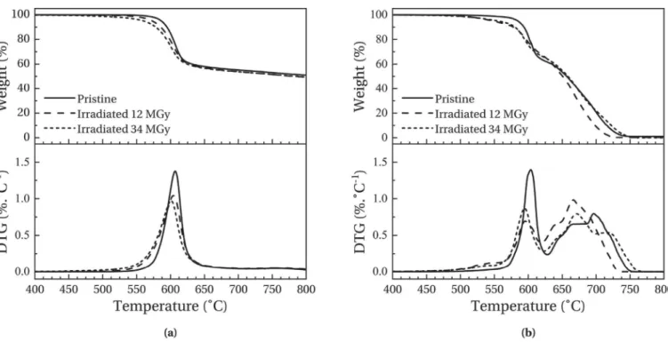
Fig. 2-(a) and 2-(b) present the TGA thermograms obtained respectively under nitrogen atmosphere and under air atmosphere for high-crystallinity samples. The top data show the normalised weight m/m0 while the bottom data show the Derivative
Ther-moGravimetric (DTG) curves. Since the TGA thermograms of low-crystallinity samples present the same degradation behaviour and the same evolutions after irradiations than high-crystallinity sam-ples, for purpose of clarity they are not presented here.
Under nitrogen or air atmosphere, an intense degradation phenomenon is observed with a maximum intensity at around 600$C. Vasconcelos et al. [20] associated this degradation with
random chain scissions between aromatic cycles and ether or ke-tone bonds independently of the atmosphere. Under oxidising conditions, a second degradation phenomenon is present, leading to a complete decomposition of sample, which results from oxidation of the first degradation residue. This last degradation seems to occur in three manifestations, respectively at around 650$C, 675$C and 700$C. However, they have not been associated
with specific degradation phenomena and literature does not report their origins.
Irradiated samples show an overall decline of their thermal stability. Under nitrogen atmosphere, the temperature position of peak maximum and peak intensity of the primary degradation decrease with an increasing dose which is consistent with the study of Kornacka [12]. An increase in the peak width with dose is also observed. In the case of oxidising atmosphere, same observation can be made despite a peak intensity no longer proportional to dose. These evolutions imply that irradiations necessarily induce chemical modifications of the polymer. Moreover, irradiated sam-ple thermograms performed under air show a new degradation phenomenon near 550$C. This new peak has been associated with
short polymer chains created during irradiation and which degrade at lower temperatures. It indicates that chain scission phenomenon occurs during irradiations. This observation confirms the presence of chemical modifications. Finally, the last degradation phenome-non shows different evolutions after irradiation: an amplification of the two first steps of the degradation and a disappearance of the third one. In the case of the highest dose, a new step can also be observed at higher temperature (around 725$C). These
observa-tions are an additional evidence that irradiaobserva-tions induce chemical
Fig. 1. Dose depth profiles in high-crystallinity PEEK samples (———) and for different exposure times to the geostationary orbit electronic environment (dde).
modifications. However, due to the poor understanding of the degradation mechanism steps, any further interpretations of these evolutions would not be reliable.
3.2. Physico-chemical structure evolutions
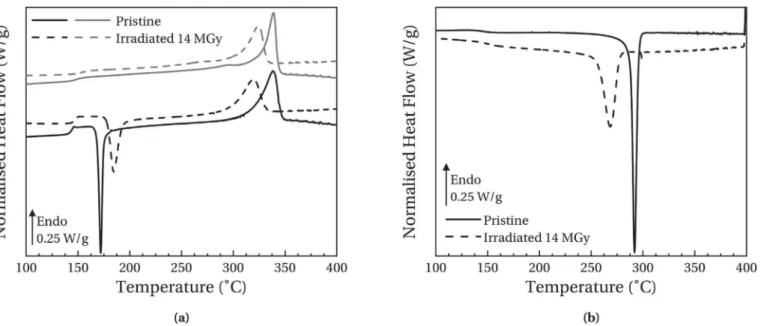
Fig. 3-(a) and 3-(b) present respectively the evolution of heating and cooling thermograms with the dose for high-crystallinity samples. Thermal transition parameters extracted from the anal-ysis of these curves are reported for both physical structures as a function of dose inTable 1.
For the pristine sample, a glass transition temperature of 158$C
is measured during the first heating run. On the second heating run, Tgdecrease of almost 10$C. This phenomenon has been associated
with internal stresses induced by manufacturer during film pro-cessing and which relax during the first run. Finally, between 1st and 2nd heating run, an increase in the crystallinity ratio
c
c is observed. This evolution is associated with the presence of a shoulder below the melting peak on the 2ndheating run thermo-grams. This phenomenon is due to secondary crystallisation which is well documented for the PolyArylEtherKetone polymer family [21,22].Irradiated sample thermograms show significant evolutions af-ter irradiations.
Fig. 3. Heating thermograms (a) and cooling thermograms (b) of high-crystallinity samples as a function of dose. First heating runs are represented in black lines and second heating runs in grey lines.
( Second heating runs shows that Tgincrease by 6$C (cf.Table 1)
for a dose of 34 MGy. This shift to higher temperatures is linked to a decrease in macromolecules mobility which is often related to cross-linking. Moreover, the crystallisation temperature Tc
measured during the cooling run shifts to lower temperatures with the dose. This is consistent with a cross-linking phenom-enon which induces slower crystallisation kinetics: in the melting state, cross-links limit the reorganisation of polymer chains in crystallites. A broadening of the crystallisation peak is also observed with an increasing dose which is indicative of a more heterogeneous medium after irradiation and leads to a greater distribution of crystallisation kinetics.
( Melting temperature Tmmeasured during the first heating run
(339$C for pristine sample) decreases significantly with the
dose: about 20$C for the highest dose. This shift is associated
with less stable crystalline entities which require less energy to melt. Thus, irradiations decrease the stability of the crystalline phase by creating defects in it. Moreover, the crystallinity ratio decreases as well in irradiated samples. This observation sug-gests that the created defects lead to a decrease in crystallite size. This hypothesis is confirmed by Yoda which observed by X-Ray Diffraction an average decrease of 15% in crystallite size in electron-irradiated PEEK samples [23]. Furthermore, a broad-ening of the melting peak is observed with ageing which in-dicates that irradiations also increase the crystallite size distribution.
( Finally, the decrease in Tmand
c
c during the second run con-firms the chemical nature of observed modifications. Indeed, even after passing by the molten state, samples do not recover their initial state. Furthermore, irradiations limit the secondary crystallisation phenomenon observed during the second heat-ing run:Dc
c value between first and second heating run de-creases in irradiated samples and even becomes negative for the highest ageing.Fig. 4-(a) and 4-(b) present respectively heating and cooling thermograms of low-crystallinity pristine and irradiated samples.
During the first heating run, a cold crystallisation peak is observed at a temperature Tccof 172$C for the pristine sample.
Moreover, a glass transition temperature of 144$C is measured
during this run. This lower value compared to high-crystallinity samples can be explained by a decrease in rigid amorphous phase fraction RAF [24,25]. Indeed, lower quantity of crystalline entities induces a lower RAF and therefore, increase the amorphous phase mobility.
( Low-crystallinity irradiated sample shows similar evolutions compared to those of high-crystallinity samples. However, modifications are more significant in low-crystallinity samples. For example, for a similar dose (14 MGy), the glass transition temperature during the second run increases by 5$C for the
low-crystallinity sample and just 3$C for the high-crystallinity
sample. This more significant evolution compared to high-crystallinity samples indicates that the presence of crystallites increases the stability of samples against electronic irradiation. This trend has already been observed by Hegazy et al. who have detected higher gas emissions in amorphous samples than in semi-crystalline samples [26]. Their results corroborate the hypothesis that crystalline phase stabilises samples in the standpoint of cross-linking.
( The evolutions are also more significant in the case of melting temperature. However, the origin of crystalline entities between low and high crystallinity samples is not the same. For high-crystallinity samples, crystallites are present during the irradi-ation and therefore, the decrease in Tmand
c
cis due to the direct modification of crystallite size. For low-crystallinity samples, the majority of crystallites which melt at Tmon the first heating runappeared during the cold crystallisation. Thus, the decrease in Tmis mainly due to a limited cold crystallisation phenomenon
induced by the cross-linking of macromolecules. This is confirmed by the increase in cold crystallisation temperature and the decrease in
D
Hcc. The values ofD
Hccare not reported inthe table but decrease from 23 J.g-1in pristine sample to 20 J.g-1 in irradiated sample. Furthermore, the cold crystallisation peak broaden after irradiation indicating an increase in the medium heterogeneity. Finally, the value of
c
cmeasured during the first heating run decrease with an increasing ionising dose. This behaviour is the same than in high-crystallinity sample. Since equation(2)takes into account cold crystallisation, this decrease is due to the direct damaging of crystallites during irradiation.Fig. 4. Heating thermograms (a) and cooling thermograms (b) of low-crystallinity samples as a function of dose. First heating runs are represented in black lines and second heating runs in grey lines.
These evolutions of physical and chemical structures are anal-ogous to those observed by Hegazy et al. in the case of amorphous and semi-crystalline PEEK samples subjected to
g
irradiations un-der vacuum [5]. In their study, they also associated these evolutions with cross-linking of amorphous phase. Thus, ageing mechanisms under electronic irradiations or underg
irradiations look to be the same.3.3. Evidence of cross-linking through absorption tests
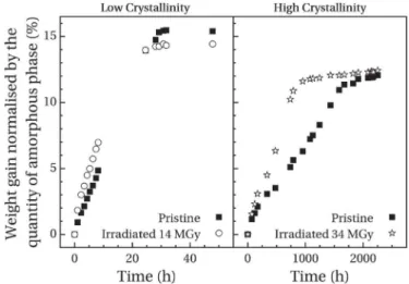
Fig. 5shows the normalised acetone weight gain as a function of immersion time for low-crystallinity and high-crystallinity sam-ples. In order to highlight any evolutions for high-crystallinity samples, swelling tests were carried out only for the highest dose. Some qualitative observations can be made from data inFig. 5. Whether for pristine or irradiated samples, mass uptake shows faster absorption kinetics and higher equilibrium weight gain m∞
for low-crystallinity samples. Indeed, several studies have observed this behaviour in polymer systems [27,28]. It has been linked with the fact that only the amorphous phase can absorb penetrants. Indeed, the higher density of crystalline phase limits absorption phenomena. Thus, with an increasing amorphous phase ratio the quantity of penetrant which can be absorbed increases but also, its diffusion through the polymer is fastest due to less crystallites. In the case of PEEK, this behaviour has been observed as well by Stober and Seferis with methylene chloride [19].
After irradiation, faster absorption kinetics are observed in both physical structures. This evolution has been associated with the decrease in crystallinity observed in irradiated samples by DSC analysis. Indeed, the quantity of crystalline entities being lower, the penetrant diffusion is easier and therefore, the absorption rate in-creases. Regarding the value of equilibrium weight gain, a decrease is observed after irradiation for the low-crystallinity sample. First of all, it can be expected that the decrease in sample crystallinity should have induced a higher equilibrium weight gain as observed in pristine samples. This opposite evolution indicates that another parameter affects its value. Thus, it can be explained by the cross-linking of macromolecules which decreases the maximum frac-tion of penetrant that can be absorbed by the amorphous phase. Indeed, the presence of cross-links limits the swelling of the amorphous phase and therefore, decreases the volume available for the penetrant. For high-crystallinity samples, the value of m∞is
identical before and after irradiation. DSC analysis showed indeed
that the presence of crystallites stabilises the amorphous phase. Thus, the effect of cross-linking in the amorphous phase is compensated by a higher
Dc
c between pristine and irradiated samples.From the analysis of absorption data, the determination of a diffusion coefficient is only possible if the mass uptake follows a Fick's diffusion law. From Alfrey et al. [29], the weight gain m(t) normalised by its equilibrium value m∞can be fitted with the
following equation:
mðtÞ m∞
¼ Ktn (5)
Where the value of the parameter n depends on the absorption mechanism. A value of 1/2 indicates a Fickian diffusion and there-fore, the parameter K is related to the diffusion coefficient (cm2.s"1)
[30]. For a value of 1, the absorption mechanism is referred as Case II diffusion. In this case, parameter K can be related to the penetrant front velocity (cm.s"1). For a value of n between 0.5 and 1, the
diffusion is called anomalous and K cannot be associated with any physical parameters. These last two diffusion mechanisms (Case II and anomalous) are often observed when absorption tests are performed below the glass transition temperature [31]. This can be explained by comparing the characteristic time of macromolecules relaxation
t
relax:to the characteristic time of diffusiont
diff.. Indeed,above glass transition temperature,
t
relax:<t
diff:and therefore, the absorption process is controlled by the diffusion and can be describe by a Fick's law. Below glass transition temperature,t
relax:>t
diff: meaning that the process is controlled by macromolecules relaxation which induces a non-Fickian behaviour.In this study, the fit of m(t)/m∞by equation(5) reported in
Table 2 gives a value of n between 0.5 and 1 for all samples, denoting an anomalous diffusion mechanism. The absorption tests being carried out at a temperature well below the glass transition of PEEK, this behaviour is not surprising but therefore, the determi-nation of a diffusion coefficient is not possible.
Between high and low crystallinity samples, the parameter K increases. Indeed, its value is related to diffusion kinetics and, since diffusion processes are faster in amorphous samples, this increase is linked to the decrease in
c
c. Regarding parameter n, its value decreases with increasingc
c. For polymers, anomalous and Case II diffusion mechanisms are related to the presence of amorphous phase. Thus, when the polymer becomes closer to a fully crystalline theoretical state, the diffusion mechanism gets closer to a Fickian behaviour. Moreover, numerous studies have demonstrated that amorphous polymers present Case II behaviour, i.e. a parameter n equal to 1 like Weisenberger et al. for methanol in PMMA [32] or Qin et al. for acetone in PolyCarbonate [33].After irradiation, an increase in parameter K is observed for both crystallinity ratio. This evolution confirms the faster diffusion ki-netics observed onFig. 5and which has been associated with the decrease in
c
c. For the parameter n, opposite evolutions areFig. 5. Evolution with the dose of weight gain kinetics for low-crystallinity samples andhigh-crystallinity samples.
Table 2
Parameters K and n obtained from the fit of m(t)/m∞ by equation(5)compared tocc
obtained from 1stheating runs in DSC analysis.
K n cc (s-n) (%) High Crystallinity Pristine 1.6 ! 10e3 0.85 34.1 Irradiated 34 MGy 2.1 ! 10e3 0.89 25.8 Low Crystallinity Pristine 43 ! 10e3 0.95 12.8 Irradiated 14 MGy 120 ! 10e3 0.65 06.5
observed between high and low crystallinity samples. While a little increase is observed for the high-crystallinity samples, an impor-tant decrease is observed for amorphised samples: the diffusion process becomes closer to a Fickian behaviour. This could indicates that cross-linking of the amorphous phase limits the influence of chains relaxation on the diffusion process and therefore, leads to a quasi-Fick mechanism. For high-crystallinity samples, the influence of cross-linking could be negligible in front of the increase in amorphous phase quantity and therefore, the diffusion gets closer to a Case II mechanism.
3.4. Influence of irradiations on the mechanical behaviour
Fig. 6 presents the DMA thermograms of high-crystallinity samples, pristine and irradiated.
Loss modulus E00thermogram of the pristine sample shows two
distinct relaxation phenomena. At low temperature, the broad peak at about "90$C is labelled
g
relaxation. It has been associated in theliterature with dipolar entities which can interact with water like ketone groups present on the main chain [34,35]. Literature also highlights another secondary relaxation named
b
, located at around "60$C, associated with the oscillation of phenyl groupsaround their axis. However, in elongational strain mode, this relaxation is difficult to point out. At higher temperature, the intense peak near 150$C corresponds to the viscoelastic relaxation
(i.e. the mechanical manifestation of the glass transition) also named
a
relaxation.Two clear evolutions can be pointed out on the thermograms of irradiated samples. On one hand, an increase in Tawith the dose is observed. Like for the increase in Tg, this indicates that the
cross-linking induced by irradiation decreases the macromolecules mobility. This shift to higher temperature is also accompanied with an increase in the width of the viscoelastic relaxation peak. This broadening is attributed to the increase in heterogeneities around relaxing entities responsible of the
a
relaxation.On the other hand, a higher rubber modulus value Erubberis
observed in irradiated samples. In the rubbery state, the mechan-ical properties of a thermoplastic polymer are maintained by the presence of crystallites. However, the decrease in crystallinity in irradiated samples observed by DSC should induce a lower Erubber.
Thus, this increase can only be explained by a cross-linking phe-nomenon which limits the mobility of macromolecules on the rubbery plateau.
Moreover, no change in
g
relaxation mode is observed, neither on the position nor on the amplitude. This relaxation being asso-ciated with a localised macromolecular mobility, this observation indicates that the density of the cross-linking is low and therefore, not sufficient to have a local influence. Thus, the characteristic length between cross-links is smaller than the size of relaxing en-tities involved in viscoelasticity but larger than those of theg
relaxation. In other words, some relaxing entities involved in
g
relaxation are probably modified by the irradiation but their me-chanical response are hidden in the response of unmodified entities.
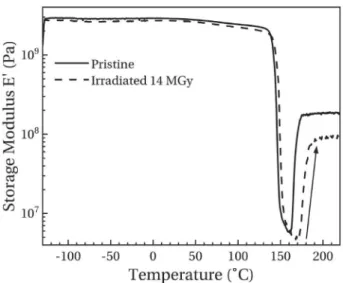
Fig. 7 presents the storage modulus thermogram of low-crystallinity samples before and after irradiation. As for high-crystallinity samples, the modulus drops at almost 150$C due to
the viscoelastic transition. The amplitude of this drop is higher than for high-crystallinity samples due to the lower quantity of crys-tallites. At higher temperatures, an increase in modulus, symbol-ised by a rising arrow on the graph, is observed. This behaviour is associated with the cold crystallisation phenomenon. Indeed, the increase in crystallinity limits the mobility of macromolecules and therefore, increases the value of Erubber.
After irradiation, these two phenomena are shifted to higher temperatures which is consistent with DSC analyses. However, the value of Erubberafter the cold crystallisation decreases in irradiated
sample in contrast to high-crystallinity samples. In this case, crys-tallites at the origin of samples mechanical resistance were formed during the analysis. Thus, this decrease is the consequence of the limited cold crystallisation which leads to lower crystallinity ratio and therefore, a lower rubber modulus.
4. Conclusion
This work studied, through different experimental approaches, the influence of electronic irradiations on the physical an chemical structures of PolyEtherEtherKetone. In this way, the SIRENE facility installed at ONERA was used to irradiate samples, under high vacuum and at room temperature, with high-energy electrons (350 keV) and with high current beam densities (up to 60 nA.cm"2). Three irradiation campaigns were carried out leading to three average doses: 1.2 ! 107Gy and 3.4 ! 107Gy for the high-crystallinity samples, 1.4 ! 107Gy for the low-crystallinity sample. DSC analyses revealed that irradiations induced modifications of
Fig. 7. Storage modulus thermogram of low-crystallinity pristine and irradiated samples.
Fig. 6. DMA thermograms of high-crystallinity pristine and irradiated samples. Storage moduli are represented in black lines and loss moduli in grey lines.
both physical and chemical structures of PEEK. The decrease in the melting temperature and the crystallinity ratio of high-crystallinity samples has been linked to the decrease in crystallite size during irradiation. In the case of low-crystallinity samples, these decreases are due to a limited cold crystallisation which is also seen through the increase in Tcc. This indicates a decrease in macromolecules
mobility. Moreover, in both types of samples, an increase in the glass transition temperature has been observed and is consistent with a decrease in mobility. Due to the irreversibility of these modifications revealing their chemical nature, it has been concluded that irradiation induces preponderantly cross-linking of macromolecules. This behaviour has already been observed under
g
irradiations [5]. Nonetheless, chain scission phenomenon has also been observed through the degradation of smaller-length chains in TGA.Through acetone absorption tests, this cross-linking has been highlighted by the decrease in the equilibrium weight gain in low-crystallinity samples. Indeed, cross-links limits the swelling of amorphous phase and therefore, decreases the fraction of pene-trant which can be absorb. It has also been shown that the decrease in crystallinity ratio induces an increase in absorption kinetics.
Finally, DMA tests showed that the localised
g
relaxation was unmodified after irradiation. This allowed us to conclude that cross-linking density is low. Moreover, an opposite evolution of Erubber has been observed between both physical structures ofsamples and has been linked to the origin of crystallites responsible of the mechanical behaviour of rubbery plateau.
Acknowledgement
The authors would like to thank the CNES for technical support (funding of the SIRENE facility) and the R!egion Occitanie for financial support in this project.
References
[1] R.D. Leach, Failures and Anomalies Attributed to Spacecraft Charging, NASA Marshall Space Flight Center, 1995. Tech. Rep. Tech. Rep. NASA-RP-1375. [2] A. Roggero, E. Dantras, T. Paulmier, C. Tonon, S. Dagras, S. Lewandowski,
D. Payan, Inorganic fillers influence on the radiation-induced ageing of a space-used silicone elastomer, Polym. Degrad. Stab. 128 (2016) 126e133. [3] A. Roggero, E. Dantras, T. Paulmier, C. Tonon, S. Lewandowski, S. Dagras,
D. Payan, Electrical conductivity of a silicone network upon electron irradia-tion: influence of formulation, J. Phys. D Appl. Phys. 49 (2016) 505303. [4] T. Sasuga, M. Hagiwara, Radiation deterioration of several aromatic polymers
under oxidative conditions, Polymer 28 (1987) 1915e1921.
[5] E.-S.A. Hegazy, T. Sasuga, T. Seguchi, Irradiation effects on aromatic polymers: 3. Changes in thermal properties by gamma irradiation, Polymer 33 (1992) 2911e2914.
[6] H. Nakamura, T. Nakamura, T. Noguchi, K. Imagawa, Photodegradation of PEEK sheets under tensile stress, Polym. Degrad. Stab. 91 (2006) 740e746. [7] G. Ajeesh, S. Bhowmik, V. Sivakumar, L. Varshney, V. Kumar, M. Abraham,
Investigation on polyetheretherketone composite for long term storage of nuclear waste, J. Nucl. Mater. 467 (2015) 855e862.
[8] L. Yang, Y. Ohki, N. Hirai, S. Hanada, Aging of poly(ether ether ketone) by heat and gamma rays ee its degradation mechanism and effects on mechanical, dielectric and thermal properties, Polym. Degrad. Stab. 142 (2017) 117e128. [9] T. Sasuga, N. Hayakawa, K. Yoshida, M. Hagiwara, Degradation in tensile
properties of aromatic polymers by electron beam irradiation, Polymer 26 (1985) 1039e1045.
[10] T. Sasuga, M. Hagiwara, Mechanical relaxation of crystalline poly(aryl-ether-ether-ketone) (PEEK) and influence of electron beam irradiation, Polymer 27 (1986) 821e826.
[11] S. Fujita, K. Shinyama, M. Baba, Dielectric properties of electron beam irra-diated PEEK, 10th International Symposium on Electrets (ISE 10), in: Pro-ceedings (Cat. No.99 CH36256, 1999, pp. 115e118.
[12] E.M. Kornacka, G. Przybytniak, A. Nowicki, Radical processes initiated by ionizing radiation in PEEK and their macroscopic consequences, Polym. Adv. Technol. 30 (2019) 79e85.
[13] D. Drouin, A.R. Couture, D. Joly, X. Tastet, V. Aimez, R. Gauvin, CASINO V2.42eeA fast and easy-to-use modeling tool for scanning electron micro-scopy and microanalysis users, Scanning 29 (2007) 92e101.
[14] H. Demers, N. Poirier-Demers, A.R. Couture, D. Joly, M. Guilmain, N. de Jonge, D. Drouin, Three-dimensional electron microscopy simulation with the CA-SINO Monte Carlo software, Scanning 33 (2011) 135e146.
[15] A. Sicard-Piet, S. Bourdarie, D. Boscher, R.H.W. Friedel, M. Thomsen, T. Goka, H. Matsumoto, H. Koshiishi, A new international geostationary electron model: IGE-2006, from 1 keV to 5.2 MeV, Space Weather 6 (2008) S07003. [16] D.J. Blundell, B.N. Osborn, The morphology of poly(aryl-ether-ether-ketone),
Polymer 24 (1983) 953e958.
[17] M.A. Grayson, C.J. Wolf, The solubility and diffusion of water in poly(aryl-ether-ether-ketone) (PEEK), J. Polym. Sci., Polym. Phys. Ed. 25 (1987) 31e41. [18] G. Mensitieri, A. Apicella, J.M. Kenny, L. Nicolais, Water sorption kinetics in
poly(aryl ether ether ketone), J. Appl. Polym. Sci. 37 (1989) 381e392. [19] E.J. Stober, J.C. Seferis, Fluid sorption characterization of PEEK matrices and
composites, Polym. Eng. Sci. 28 (1988) 634e639.
[20] G.d.C. Vasconcelos, R.L. Mazur, B. Ribeiro, E.C. Botelho, M.L. Costa, Evaluation of decomposition kinetics of poly (ether-ether-ketone) by thermogravimetric analysis, Mater. Res. 17 (2013) 227e235.
[21] P. Cebe, S. Hong, Crystallization behaviour of poly(ether-ether-ketone), Polymer 27 (1986) 1183e1192.
[22] L. Quiroga Cort!es, N. Causs!e, E. Dantras, A. Lonjon, C. Lacabanne, Morphology and dynamical mechanical properties of poly ether ketone ketone (PEKK) with meta phenyl links, J. Appl. Polym. Sci. 133 (2016) 43396.
[23] O. Yoda, The crystallite size and lattice-distortions in the chain direction of irradiated poly (aryl-Ether-Ketone), Polym. Commun. 26 (1985) 16e19. [24] P. Huo, P. Cebe, Effects of thermal history on the rigid amorphous phase in
poly(phenylene sulfide), Colloid Polym. Sci. 270 (1992) 840e852.
[25] S.Z.D. Cheng, M.Y. Cao, B. Wunderlich, Glass transition and melting behavior of poly(oxy-1,4-phenyleneoxy-1,4-phenylenecarbonyl-1,4-phenylene) (PEEK), Macromolecules 19 (1986) 1868e1876.
[26] E.-S.A. Hegazy, T. Sasuga, M. Nishii, T. Seguchi, Irradiation effects on aromatic polymers: 2. Gas evolution during electron-beam irradiation, Polymer 33 (1992) 2904e2910.
[27] L. Perrin, Q.T. Nguyen, R. Clement, J. Neel, Sorption and diffusion of solvent vapours in poly(vinylalcohol) membranes of different crystallinity degrees, Polym. Int. 39 (1996) 251e260.
[28] V. Compa~n, L.F. Del Castillo, S.I. Hern!andez, M.M. L!opez-Gonz!alez, E. Riande, Crystallinity effect on the gas transport in semicrystalline coextruded films based on linear low density polyethylene, J. Polym. Sci., Polym. Phys. Ed. 48 (2010) 634e642.
[29] T. Alfrey, E.F. Gurnee, W.G. Lloyd, Diffusion in glassy polymers, J. Polym. Sci., Polym. Symp. 12 (1966) 249e261.
[30] N.A. Peppas, L. Brannon-Peppas, Water diffusion and sorption in amorphous macromolecular systems and foods, J. Food Eng. 22 (1994) 189e210. [31] L. Masaro, X. Zhu, Physical models of diffusion for polymer solutions, gels and
solids, Prog. Polym. Sci. 24 (1999) 731e775.
[32] L.A. Weisenberger, J.L. Koenig, An NMR imaging study of methanol desorption from partially swollen PMMA rods, Macromolecules 23 (1990) 2454e2459. [33] W. Qin, Y. Shen, L. Fei, NMR imaging of acetone diffusion process in
poly-carbonate, Chin. J. Polym. Sci. 11 (1993) 358e363.
[34] J.E. Harris, L.M. Robeson, Miscible blends of poly(aryl ether ketone)s and polyetherimides, J. Appl. Polym. Sci. 35 (1988) 1877e1891.
[35] M. Coulson, L. Quiroga Cort!es, E. Dantras, A. Lonjon, C. Lacabanne, Dynamic rheological behavior of poly(ether ketone ketone) from solid state to melt state, J. Appl. Polym. Sci. 135 (2018) 46456.