Open Archive TOULOUSE Archive Ouverte (OATAO)
OATAO is an open access repository that collects the work of Toulouse researchers and
makes it freely available over the web where possible.
This is an author-deposited version published in :
http://oatao.univ-toulouse.fr/
Eprints ID : 15799
To link to this article : DOI : 10.1016/j.ijrmms.2016.03.002
URL :
http://dx.doi.org/10.1016/j.ijrmms.2016.03.002
To cite this version :
Yahiaoui, Malik and Paris, Jean-Yves and
Delbé, Karl and Denape, Jean and Gerbaud, Laurent and Dourfaye,
Alfazazi Independent analyses of cutting and friction forces applied
on a single polycrystalline diamond compact cutter. (2016)
International Journal of Rock Mechanics and Mining Sciences, vol.
85. pp. 20-26. ISSN 1365-1609
Any correspondence concerning this service should be sent to the repository
administrator:
[email protected]
Independent analyses of cutting and friction forces applied on a single
polycrystalline diamond compact cutter
M. Yahiaoui
a,n, J.-Y. Paris
a, K. Delbé
a, J. Denape
a, L. Gerbaud
b, A. Dourfaye
c aUniversité de Toulouse, Laboratoire Génie de Production, FrancebMines ParisTech, Centre de Géosciences, France cVarel Europe, France
Keywords: PDC cutter Cutting forces Friction forces Cutting coefficient Impact friction Erosion
a b s t r a c t
This paper presents an analysis of the excavation forces involved in the cutting action and in the friction of a cutter/rock contact. A vertical lathe-type device provided data on the forces applied on a single cutter under dry excavation conditions. A cutting device was used to perform cutting experiments with unworn and worn cutters. A tribometer was used to perform friction tests on the cutters wear flat previously realized with the vertical lathe. The experiments display results conform to the literature as the non-dependence of the cutting coefficient to the rock properties. Then, this study focuses on the cutting forces and explains that these forces include a component of rock shearing and impact friction. The impact friction is induced by the interaction between ejected rock particles and the cutting active area. The evidence of this impact friction is then brought by the formation of an eroded zone on the cutting active area.
1. Introduction
The drilling industry mainly uses two families of tools: roller cone bits for the hardest rock formations and drag bits in softer rocks. Because of their great excavation performances, drag bits have an increasing market share reaching more than 60% in 2014 and estimated at 80% in 2020 [1]. During excavation, drag bits operate by shear mode and are mostly damaged by abrasion[2]. Therefore, the increase in market share is also explained by the progresses made on materials and mechanical studies to assess their wear resistance.
Drag bits are formed by tens of polycrystalline diamond com-pact (PDC) cutters. These bits have a specific design allowing a homogenous distribution of stresses and wear on the cutters[3]. Consequently, laboratory experiments are often performed on a single cutter. This strategy is also justified by the accurate control of experimental conditions and the easier interpretation of me-chanical data obtained with a single cutter[4]. In this way, Fair-hurst and Lacabanne[5]first decomposed the forces applied on a single cutter as cutting forces and friction forces. The cutting forces are applied on the cutter front active area. The friction forces ap-pear between the cutters and the rock when a significant wear flat
is formed at the cutter tip [6]. These authors introduced then strong hypotheses as the independence between these friction and cutting forces. Detournay and Defourny[7]also assumed that, at the beginning of a test, before the formation of a wear flat, the forces applied on the cutter are equal to the cutting forces. Since, the single cutter approach and these hypotheses are broadly used to asses cutters quality[8]. Thereby, the study of cutter/rock in-teractions decomposed at the cutter active areas can bring new developments for the understating of drill bits excavation and wear performances.
The aim of this work is to study independently the cutting and the friction components applied to a single cutter. First, experi-ments equivalent to the excavation conditions but in dry condi-tions were performed to highlight the results obtained with the independence hypothesis. Then, cutting tests with different cutter wear flats, cutting depths and rocks were carried out to study the cutting forces. Finally, friction tests without penetrating the rock were done to only measure friction forces applied between cutters with different wear flats and rocks.
2. Single cutter/rock contact
The PDC cutters used in this study are cylindrical with a dia-meter of 13.4 mm and a height of 10 mm. They are formed by a tungsten carbide-cobalt substrate surmounted by the PDC part. The thickness of this PDC part is 2 mm. The PDC part has a chamfer
http://dx.doi.org/10.1016/j.ijrmms.2016.03.002
n
Corresponding author. Address: Ecole Nationale d'Ingénieurs de Tarbes, 47 avenue d'Azereix, 65016 Tarbes, France.
E-mail addresses:[email protected],
of 45° ! 0.4 mm. The PDC cutters have a coarse PDC microstructure with a mean diamond grains size of17±4 mμ .
Concerning the single cutter contact mechanics, two main hy-potheses are commonly used:
"
The independence between the cutting components applied on the cutting active area Ac(Fig. 1b) and the friction components applied on the wear flat Af(Fig. 1c);"
At the beginning of a test, the cutting is pure. The friction coefficientμ
defined by friction components is equal to zero as there is no surface for the friction to be applied on.These hypotheses can simply be expressed by two equations relating the overall forces applied to the cutter and the associated cutting and friction components:
μ ε = + = + ( ) = + = + = + ( ) ( ) ⎪ ⎪ ⎧ ⎨ ⎩ F F F F F F A F F F F F 0 0 1 T Tf Tc Tf T Nf c N Nf Nc Nf N
The cutting forces are considered constant during excavation and proportional to the cutting active area Ac. The coefficient of proportionality is the intrinsic specific energy
ε
depending on rock mechanical properties. The friction increases with the wear flat formation as the load required to maintain the constant cutting depth increases. Accordingly, Detournay and Defourny[7]showed that a linear relation could be established between the transverse force FTand the normal force FN (withζ
the cutting coefficientdefined by the cutting components):
μ ε μζ
= + ( − ) ( )
FT FN 1 Ac 2
This linear law can also be expressed by relating the specific energy E (i.e. the ration between FT and Ac) and the drilling strength S (i.e. the ration between FNand Ac):
μ ε μζ
= + ( − ) ( )
E S 1 3
3. Experimental campaign 3.1. Excavation device
A vertical lathe-type device was used to realize dry excavation experiments. Cutters brazed on sample holders were adjusted downward on the lathe shaft. Ring-stone counterfaces were made of a manufactured mortar rock (1 m in external diameter, 0.5 m in internal diameter and 0.6 m thick with a density of 2150 kg m−3). The mortar has a homogeneous chemical composition (silica content of 60 wt.%) and mechanical properties (compressive strength of 48 MPa and young modulus of 78 GPa). The experi-ments were carried out using a normal loadFNranged from 3000 to 5000 N, a back rake angle
α
of 15° and a mean cutting speed of−
1.8 m s 1. The cutting depth
δ
was maintained at 2 mm. The tests were conducted in atmospheric environment and no lubricant was added into the contact to significantly wear the PDC cutters. The experiments were conducted over an equivalent excavation dis-tance of 8500 m. During these experiments, a wear flat area Af isFig. 1. Contact configuration of the vertical lathe: (a) overall cutter/rock contact model withFNandFTthe applied forces, α the back rake angle,Acthe cutting active area and
Afthe wear flat area; (b) cutting componentsF
formed at the tip of the cutter (Fig. 1a). At the end of each se-quence, the height of material lost h was measured to calculate the cutting active area Ac. The cutters were worn only in their PDC part. The tests were performed two times giving enough repeatability.
The vertical lathe was also used to prepare the cutters for the independent cutting and friction experiments. Two wear states at
worn height h of 0.30 70.02 mm and 0.457 0.02 mm were per-formed on two different cutters (Fig. 2). These worn heights are associated to wear flat areas Af of 3.070.5 mm2 and
5.370.8 mm2
. The wear flats are only formed in the PDC part and the WC-Co substrate was not worn.
3.2. Cutting device
The cutting device was used to perform short cutting experiments in dry condition with different natural rocks. The cutting device is composed by a load arm where the PDC cutters are fixed using a sample holder and a rotating plate where different cored rocks can be placed. Several cutting depths were set between 0 and 3 mm. The cutting active area Ac was calculated accordingly to the cutting depth. The cutting speed was set at4 mm s−1. The cutting was per-formed for a few seconds until a permanent state was established (i.e. constant contact forces and cutting depth). These experimental conditions do not lead to any significant wear of the cutter.
Four different rocks were selected: two limestones and two sandstones. This selection allows interesting variations of physical and mechanical properties as the density, the porosity and the compressive resistance (Table 1).
The cutting tests were performed with an unworn cutter and the three cutters previously worn using the wear lathe.
3.3. Tribometer
A rotary tribometer was used to perform friction tests on the worn cutters (Fig. 3). These tests were performed with a normal
Fig. 2. View of a wear flat with a worn height h of 0.17 mm.
Table 1
Properties of rocks used for the cutting experiments with the density ρ, the por-osity ϕ and the compressive resistanceRc.
Rocks ρ(g cm−3) ϕ(%) Rc(MPa) Buxy limestone 2.6 2 100 Lacôme limestone 2.3 12 80 Vosges sandstone 2.2 22 42 La Rhune sandstone 2.1 3 130
Cutter
Rock
Rotation
Fig. 3. View of the cutter/rock contact on the rotary tribometer (counterclockwise rock rotation).
1600
1200
800
400
0
Transverse force,
F
T(N)
6000
4000
2000
0
Normal force, F
N(N)
µ
F
T c= ε·A
c= F
T(0)
F
N c= ζ· F
T c= F
N(0)
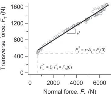
Fig. 4. Linear evolution of the transverse force in function of the normal force.
Table 2
Coefficients obtained from the Detournay–Defourny law of excavation (Ac is the mean value of the cutting active area during the tests). μ 0.1970.01 ζ 1.1770.03 ε(MPa) 4472 ( ) Ac mm2 12.370.1 F Nc(N) 640751 F Tc(N) 544727
load of 64 N and a sliding velocity of 0.5 m s−1. The experiments were conducted for a few minutes until permanent sliding con-ditions. The sliding direction was set at the direction opposite of the cutter excavation direction to avoid any cutting action. The La Rhune sandstone was used for these friction experiments. Again, the cutters worn with the wear lathe were reused for these friction experiments.
4. Results
4.1. Excavation tests
The excavation tests show that the forces applied to the cutters verify the Detournay–Defourny law (Fig. 4). The transverse force is linear with the normal force during these wear experiments. In other words, when the cutter wears, the friction at the wear flat increases linearly with the load applied on it (Amontons–Cou-lomb's friction law) to maintain a constant cutting depth.
Accordingly, the experiment results give the friction coefficient, the cutting coefficient and the specific intrinsic energy (Table 2).
During the excavation, the cutting active area slightly changes depending on the wear state of the cutters. The mean value of the cutting active area is 12.3±0.1 mm2. The average normal com-ponent of cutting forces is 6407 51 N. The average transverse component of cutting forces is 544 727 N.
4.2. Cutting tests with unworn cutters
The cutting tests with an unworn cutter imply that the overall forces applied on the cutter are equal to the cutting components (i.e.FN=FNcandFT=FTc). As expected, the transverse cutting force is proportional to the normal cutting force (Fig. 5a). This ob-servation was confirmed for all the experimented rocks. Further-more, the calculated cutting coefficient
ζ
is identical between all these rocks and for all the cutting depth with the value of 0.79 70.01. First of all, this result could indicate that with this experimental configuration the cutting mechanisms realized at the cutter/rock interface are quite similar. However, as already de-scribed in previous studies[9,10], these tests show that there are two cutting regimes depending on the cutting depth (i.e. on the cutting active area) (Fig. 5b). These two cutting regimes are linked500
400
300
200
100
0
F
T(N)
400
300
200
100
0
F
N(N)
La Rhune sandstone Buxy limestone Lacôme limestone Vosges sandstone ζ = 0,79 ± 0,01 1/ζ500
400
300
200
100
0
F
T(N)
20
15
10
5
0
A
c(mm
2)
La Rhune sandstone Buxy limestone Lacôme limestone Vosges sandstoneδ (mm)
0
1
2
3
500
400
300
200
100
0
F
T(N)
120
80
40
0
R
c(MPa)
δ = 1 mm δ = 0.5 mm δ = 0.2 mmFig. 5. Evolution of the transverse force applied on an unworn cutter during cutting tests: (a) transverse force vs. normal force; (b) transverse force vs. cutting active area; and (c) transverse force vs. compressive resistance of the rocks.
to two cutting mechanisms in the cutter/rock contact: ductile and brittle.
The transverse cutting force is also function of the compressive strength (Fig. 5c). The transverse cutting force seems to follow a power law with the compressive resistance or at least two linear trends at low compressive resistance (Rc<80 MPa) and higher compressive resistance (Rc>80 MPa).
4.3. Cutting tests with worn cutters
The cutting tests with worn cutters also follow the Detournay– Defourny model (Fig. 6a). The friction is logically independent of the wear flat area Afand the friction coefficient is of 1.4070.03.
The intercept of the friction line with the E axis (i.e. ε(1−μζ)) is equal to #1177 MPa. As described in the Detournay–Defourny model (see Eq. (1)), the transverse force is proportional to the cutting active area (Fig. 6b). The coefficient of proportionality is then the intrinsic specific energy
ε
. Detournay and Defourny[7]explain that this coefficient depends on various factors as the cutter properties, the rock properties, the back rake angle, etc. Here, the coefficient
ε
is clearly independent of the cutter wear state and is equal to 7471 MPa. As expected, the excavation forces increase with the cutter wear and the area Af.From the friction coefficient
μ
, the interceptε(1−μζ)and the intrinsic specific energyε
values, the cutting coefficient is then determined at 0.82 70.09. This value does not depend on the cutter wear state. Consequently, this cutting coefficient is also si-milar to the cutting coefficient obtained with unworn cutters. 4.4. Friction testsThe friction tests show ordinary tribological results. In this way, after a transient decreasing, the friction coefficient reaches a constant value of 0.21 70.01 (Fig. 7). This transient period
600
400
200
0
Specific energy,
E
(MPa)
500
400
300
200
100
0
Drilling strength, S (MPa)
Af = 5.3 mm2 Af= 3.0 mm2µ = 1.40 ± 0.03
ε·(1 - µζ) = -11 ± 7 MPa
1000
800
600
400
200
0
F
T(N)
12
8
4
0
A
c(mm
2)
1.0
0.7
0.5
0.2
δ (mm)
Af = 5.3 mm2 Af= 3.0 mm2ε = 74 ± 1 MPa
1.5
Fig. 6. Determination of the friction and the cutting coefficients for two wear states (Afof3.0±0.5 mm2and5.3±0.8 mm2) with a Buxy limestone: (a) specific energy vs.
drilling strength and (b) transverse force vs. cutting active area.
0.8
0.6
0.4
0.2
Friction coefficient,
µ
1000
800
600
400
200
0
Test time (s)
A
f= 5.3 mm
2A
f= 3.0 mm
2Fig. 7. Evolution of the friction coefficient during friction tests for two wear states (Afof 3.070.5 mm2and 5.370.8 mm2) with a La Rhune sandstone.
Affected zone
Cutting
active area A
cWear flat
corresponds to the accommodation time of the cutter/rock con-tact. After few minutes, friction can then be considered as constant under the wear flatAf. As wear is only performed in the PDC part, the friction does not depend on the cutter wear state.
4.5. Observations
All tested cutters show a shallow visible affected zone on the tip of the cutting active area (Fig. 8). This zone represents in average an area of 37 1 mm2, i.e. 237 6% of the cutting active area
Ac.
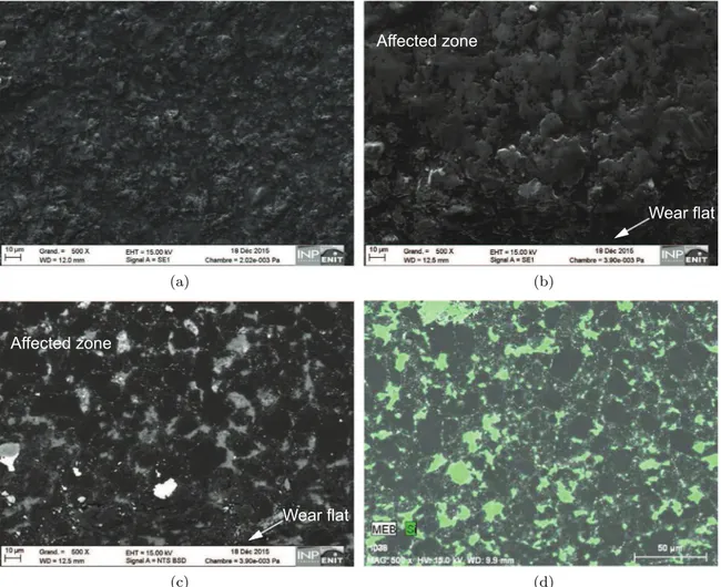
SEM observations of this affected zone display a real contrast with the rest of the front face (Fig. 9). The unaffected part of the
PDC face shows a rough surface without a defined microstructure (Fig. 9a). Otherwise, the affected zone has a smoother surface (Fig. 9b). As it can be seen on the backscatter electron image (Fig. 9c), this zone reveals the PDC microstructure. In addition, an EDX analysis coupled with the backscatter image of the affected zone shows that rock particles (i.e. mainly silica and then silicium element) are surrounding the diamond grains (Fig. 9d). These observations indicate that a mechanism of surface was performed by the rock particles in the affected zone during the tests. Deple-tion of the cobalt surrounding the diamond grains may also have occurred on this zone.
5. Discussions
As well established in tribology, friction does not depend on the apparent contact area (i.e. the wear flat Af here). The friction
coefficient
μ
is indirectly affected by the properties of the mate-rials in contact and by the experimental device through the for-mation of a third body at the interface (e.g. debris)[11]. Several authors even relate the value of frictional angle on the wear flat to the internal frictional angle of the rocks [7,12]. In this way, the changes of materials, mechanisms or particles flows involved in the cutter/rock contact explain the different friction coefficients obtained using the three devices.Otherwise, the cutting coefficient
ζ
remains constant among the various rocks used in this study with the cutting device. Ac-tually, the weakly dependence between the cutting coefficient andFig. 9. SEM images of a PDC front face after an excavation test: (a) secondary electron image of the unaffected zone; (b) secondary electron image of the affected zone; (c) backscattered electron image of the affected zone; and (d) backscattered electron image and EDX analyses of the affected zone.
Fig. 10. Illustration of the interaction cutter/rock and the cutting force components including the cutter front shearing and friction components (i.e.F′NandFT′).
the rock have been demonstrated over 300 different rocks by Ri-chard et al.[10]As the cutting coefficient can be simply expressed by the back rake angle
α
and the friction coefficient relative to the cutting active area μ′ (Eq.(4)), the front cutter/rock friction in-teraction should then be equivalent among all the selected rocks (Fig. 10). This observation can be related to a decomposition of the cutting forFcinto the force of rock shearing and the friction force generated by rock chips and particles impacts on the cutting active area. The force of rock shearing is normal to the cutting active area (i.e. F′N) and the impact friction force direction is along the front face (i.e. F′T). The shearing force is a function of rock mechanical properties. The impact friction force should mainly depend on the impact angle and the velocity of rock particles on the cutter front face while the material has less influence[13,14]. In this way, if the mechanism of excavation and rock shearing does not change, the impact friction should not vary even if the rock is different:
ζ α ψ μ ψ ζ α ζ α = = ( + ) ′ = ′ ′ = = − + ( ) ⎧ ⎨ ⎪ ⎪ ⎩ ⎪ ⎪ F F F F tan tan tan 1 tan 4 Nc Tc T N
Eventually, considering a mean cutting coefficient after the cutting experiments of 0.81 70.02, the impact friction coefficient is then of 0.41 70.02 representing an angle
ψ
of 22.387 0.02°.In real conditions, the impact friction can also be an important component. In particular, erosion mechanisms are observed when the rock particles concentration in the drilling mud increase or when the velocity of the mud circulation is high[2].
6. Conclusion
Three devices were used to study the excavation forces applied on a single cutter. These devices allow independent analyses of cutting and friction components applied on the wear flat and on the cutting active area.
First of all, the experiments display results well established in the cutter/rock contact mechanics or more broadly in contact mechanics. The sliding friction coefficient is related to the inter-facial particles flow under the wear flat brought by the materials in contact. First, the friction coefficient does not depend on the ap-parent contact area (i.e. the wear flat area and the wear state) and is constant as soon as the conformity of the contact is performed (i.e. after few minutes here). Also, in function of the cutting depth, two cutting processes can be observed in which the cutting force is proportional to the cutting active area. The intrinsic specific en-ergy is the coefficient of proportionality which depends on the rock mechanical properties. In this way, the cutting forces depend on the compressive resistance of the rock. Eventually, the cutting coefficient is function of the cutter/rock contact geometry and does not depend on the excavated rock.
On this last point, this study focuses on the cutting components and shows that the cutting process is composed by the shearing action of the rock and impact friction. The impact friction is
produced by ejected rock particles. This mechanism is attested by the observation of an eroded zone on the cutting active area.
The impact friction contribute to the increase of cutting forces and lower the excavation performances. As the wear associated to the sliding friction component and the rock excavated volume associated to rock shearing force, the erosion generated by the impact friction highlight another parameter which has to be taken into account in the quality enhancement of drill bit cutters.
Acknowledgements
This work was developed during the thesis of the University of Toulouse “Tribological behaviour of polycrystalline diamonds and graded cemented carbides WC-Co – Application to drill bits inserts and cutters for the drilling of abrasives rock formations” under the program ANR-09-MAPR-0009 of Agence Nationale de la Re-cherche.[15] We thank Armines Geosciences laboratory for per-forming the wear experiments and the Varel Europe Company for providing cutters used in this study. We also thank N. Aubazac from Laboratoire Génie de Production for her contribution in SEM observations and material characterizations.
References
1.Bellin F, Dourfaye A, King W, Thigpen M. The current state of PDC bit tech-nology. World Oil. 2010:41–46.
2.Ersoy A, Waller MD. Wear characteristics of PDC pin and hybrid core bits in rock drilling. Wear. 1995;188(1–2):150–165.
3. Gerbaud L, Menand S, Sellami H. PDC bits: all comes from the cutter rock in-teraction. In: IADC/SPE Drilling Conference; 2006:1.
4. Zijsling DH. Single cutter testing—a key for PDC bit development. In: Offshore
Europe. Vol. 87; 1987.
5. Fairhurst C, Lacabanne W. Some principles and developments in hard rock drilling techniques. In: 6th Annual Drilling and Blasting Symposium; 1956. p. 12– 25.
6. D.A. Glowka, Implications of thermal wear phenomena for PDC bit design and operation. In: 60th Annual Technical Conference and Exhibition of the Society of
Petroleum Engineers; 1985.
7.Detournay E, Defourny P. A phenomenological model for the drilling action of drag bits. Int J Rock Mech Min Sci Geomech. 1992;29:13–23.
8.Yahiaoui M, Gerbaud L, Paris J-Y, Denape J, Dourfaye A. A study on PDC drill bits quality. Wear. 2013;298–299:32–41.
9. Chaput EJ. Observations and Analysis of Hard Rocks Cutting Failure Mechanisms
Using PDC Cutters. Technical report. Imperial College London; 1992.
10.Richard T, Dagrain F, Poyol E, Detournay E. Rock strength determination from scratch tests. Eng. Geol.. 2012;147–148(0):91–100.
11.Berthier Y. Maurice Godet's third body. In: Dowson D, Taylor C, Childs T, Dalmaz G, et al., eds. The Third Body Concept Interpretation of Tribological Phenomena.
Tribology Series, Vol. 31. Liège, Belgium: Elsevier; 1996:21–30.
12. Dagrain F, Richard T. On the influence of PDC wear and rock type on friction coefficient and cutting efficiency. In: Eurock 2006—Multiphysics Coupling and
Long Term Behaviour in Rock Mechanics; 2006.
13.Ratner SB, Styller EE. Characteristic of impact friction and wear of polymeric materials. Wear. 1981;73:213–234.
14.Chen D, Sarumi M, Al-Hassani STS. Computational mean particle erosion model.
Wear. 1998;214:64–73.
15. Yahiaoui M. Comportement tribologique de diamants polycristallins et de carbures
cémentés WC-Co avec traitements de graduation - application aux inserts et tail-lants d'outils pour le forage de formations rocheuses fortement abrasives [Ph.D.