DOCTORAT DE L’UNIVERSITÉ DE TOULOUSE
Délivré par :Discipline ou spécialité :
Présentée et soutenue par :
Titre :
Ecole doctorale : Unité de recherche : Directeur(s) de Thèse : Rapporteurs : le : Membre(s) du jury :Institut National Polytechnique de Toulouse (INP Toulouse)
Mécanique, Energétique, Génie civil et Procédés (MEGeP)
Hydrodynamic modeling of poly-solid reactive circulating fluidized beds:
Application to Chemical Looping Combustion
mercredi 28 mars 2012
Nicolas NOUYRIGAT
Dynamique des Fluides
Bjorn H. Hjertager (Stavanger University) J uray de Wilde (Université Catholique de Louvain)
Olivier Simonin (IMFT-INPT) Virginie Lalam (Alstom Power Systems)
UMR 5502
Eric Climent (IMFT-INPT) Olivier Authier (EDF R&D)
Bjorn H. Hjertager (Stavanger University) J uray de Wilde (Université Catholique de Louvain)
Olivier Simonin (IMFT-INPT) IMFT -
Alstom Power Systems. Je tiens `a remercier Olivier Simonin, mon directeur de th`ese, qui m’a fait confiance et m’a fait profiter de ses comp´etences scientifiques. Je remercie ´egalement ma co-directrice de th`ese, Virginie Lalam, pour sa pr´esence et son soutien tout au long de ma th`ese.
Je remercie tout particuli`erement Renaud Ansart et Pascal Fede, pour tout le temps qu’ils m’ont consacr´e pendant ces trois ans, les connaissances qu’ils m’ont transmises et l’int´erˆet qu’ils ont port´e `a mon travail.
Merci `a Ali, Zafer, Arthurs et les autres pour leurs conseils pr´ecieux et leurs travaux sans lesquels ma th`ese ne serait pas.
Je remercie l’ensemble des membres du jury, et tout particuli`erement les rappor-teurs, Pr. de Wilde et Pr. Hjertager, d’avoir relu avec attention ce manuscrit. Je remercie ´egalement Pr. Climent et Olivier Authier pour l’int´erˆet qu’ils ont trouv´e `a ce travail.
Je tiens `a remercier l’´equipe d’Alstom qui d´eveloppe le Chemical Looping et qui a financ´e cette ´etude : Corinne B´eal et Eric Bouquet. Les ´echanges fr´equents que nous avons eu m’ont permis de mener `a bien cette th`ese.
Ce travail n’aurait pas ´et´e possible sans l’aide quotidienne d’Herv´e Neau et du ser-vice CoSiNUs, du serser-vice informatique, de Suzy et Florence.
Enfin, ceux que j’ai pu cˆotoyer durant ma th`ese ont rendu cette exp´erience plaisante et inoubliable :
- Mes mutliples co-bureaux qui ont rendu la vie au laboratoire chaleureuse, tropicale, cosmopolite, gourmande, porcine, polyglote, convalescente, mon´etis´ee, pictionaris´ee, agit´ee, sportive, caf´ein´ee et parfois studieuse.
- Le groupe PSC et tout particuli`erement ceux qui ont rendu vivants les d´ejeuners et autres pots : Jeunette, Marion, Enrica, Laurent, J-F, Florian, Pascal, Olivier, Re-naud, Herv´e, Annaig, Adriens, Erics, Thierry, Romain, Alice, Marco, Dirk, Mehdis, Aur´elien, Mambo, Anne, Moe’s et tous les stagiaires et th´esards qui font vivre ce groupe. - Les Matmeca de Toulouse qui sont partout et reli´es `a tout le monde de fa¸con incroy-able : Arnaud, Cypy, Thomas, Christian, J´erˆome...
- La Compagnie des Chercheurs d’Etoiles qui m’a permis de garder les pieds sur terre et d’occuper mes semaines.
- L’AIFOMEJ, Dominique, J-F et Florian qui m’ont fait d´ecouvrir le plaisir qu’il y a `
a faire d´ecouvrir les sciences.
- Romain, Florian, J-F pour plein de choses.
- Feu notre appart de St-Cyprien dans lequel on a pass´e de bons moments et qui a su m’occuper pendant l’´et´e consacr´e `a la r´edaction.
- Miles Davis, Nina Simone, L´eo Ferr´e et Pink Floyd qui ne m’ont pas lˆach´e.
Contents
List of Symbols 9
1 Chemical looping combustion 19
1.1 Industrial use of charcoal . . . 20
1.2 Capturing the carbon dioxide . . . 23
1.3 Chemical Looping Combustion technology . . . 27
2 CFD modeling of poly-solid reacting flows 39 2.1 Introduction to circulating fluidized beds . . . 39
2.2 Eulerian-Eulerian modeling of poly-solid reacting flows . . . 44
2.3 Modeling the reaction between Carbon and MeOx . . . 59
2.4 Remarks on the main hypothesis of gas-particle flow modeling . . . 61
2.5 Characteristic time scales in gas-particle flows . . . 63
2.6 General boundary conditions . . . 65
2.7 Presentation of N EP T U N E CF D software . . . 65
3 Application to CLC-like non-reactive poly-solid Circulating Fluidized Beds 71 3.1 The ALSTOM experimental setup . . . 73
3.2 Mono-solid cases . . . 77
3.3 Poly-solid cases . . . 86
3.4 Conclusion on mono-solid and bi-solid experiment on UTC CFB cold flow model . . . 103
4 Modeling of a binary mixture of particles with large diameter ratio 107 4.1 The CERCHAR experimental setup . . . 109
4.2 Experimental and numerical study of a bi-solid CFB with extreme flu-idization conditions . . . 112
4.3 Simulations in periodic box . . . 126
5 Appendix 171 5.1 Presentation of the cases . . . 171
5.2 Monosolid simulations . . . 171
List of symbols
Greek lettersαi Volume fraction of phase i (−)
αs Total fraction of solid (−)
αmax Maximum random packing of identical hard spheres (−)
χpq Exchange of agitation between classes due to collisions (kg · m−1· s−3)
Γg Mass transfer between species (kg · m−2· s−3)
Γk Reaction rate of the specie k (kg · m−3· s−1)
λp Bulk viscosity (P a · s)
µg Dynamic viscosity of the fluid phase (P a · s)
µp Particle dynamic viscosity of the particle phase (P a · s)
νg Gas kinematic viscosity (m2· s−1)
νgt Turbulent viscosity of the gas phase (m2· s−1)
νcol
p Particle collisional viscosity of the particle phase (m2· s −1)
νkin
p Particle kinetic viscosity of the particle phase (m2· s −1)
Πk
p→g Exchange term of turbulent kinetic energy k coming from the fluctuating motion
of particles (kg · m2· s−3)
Πεp→g Influence of the fluctuating motion of particles on k in ε equation (kg · m2· s−4
)
ρg Density of the gas phase (kg · m−3)
ρp Density of the particle phase (kg · m−3)
σk Constant of the (k − ε) model (−)
σε Variable of the (k − ε) model (−)
τ Characteristic reaction time (s)
τc
pq Characteristic collision time of a binary mixture of particles p and q (s)
τF
τgt Fluide turbulent time scale (s) τt
gp Eddy particle interaction time (s)
Θg Viscous tensor of the gas phase (kg · m−2· s−2)
ε Turbulent dissipation of the gas phase (m2· s−3)
c
αp Modified polydisperse volume fraction of solid (−)
b τc
p Modified polydisperse collision timescale (s)
q2 Constant of the (qp2− qf p) model (−)
Roman Letters
< CD > Drag coefficient (−)
< u0g,iu0p,j > Fluid-particle velocity correlations tensor components (m2· s−2)
˙
Q Molar reaction rate of the specie k (kg · m−3· s−1)
b
dp Modified polydisperse collision diameter (µm)
cp Velocity of the p-particle (m · s−1)
C12 Variable of the (k − ε) model (−)
Cµ Variable of the (k − ε) model (−)
Cεi Variable of the (k − ε) model (−)
Cq Constant of the (qp2− qf p) model (−)
D Molecular and turbulent diffusivity coefficient (m2· s−1)
dp d50 of the particle phase p (µm)
Dgp,ij Fluid-particle turbulent dispersion tensor (m2· s−1)
dpq Diameter representative from (−)
ec Inelastic restitution coefficient (−)
fp(1) Single phase p-particle velocity distribution function (−)
gpq Autocorrelation function (−)
k Turbulent kinetic energy of the gas phase (m2· s−2)
Kt
p Turbulent diffusivity coefficient (m2· s
−1)
Lp Scalar representing the number of particles (−)
Mc Total mass of carbon in the bed (kg)
Pg Mean pressure of the gas phase (kg · m−1· s−2)
Pp Granular pressure (kg · m−2· s−2)
Qk
z Mass flow rate of the specie k at z (m3· s
−1)
qgp Fluid-particle velocity correlation (m2· s−2)
R Universal gas constant (J · mol−1· K−1)
Rg,ij Reynolds stress tensor of the gas phase (m2· s−2)
Rep Particulate Reynolds number (−)
T Temperature (K or◦C)
V Volume of the domain (m3)
Vd Drift velocity (m · s−1)
Vf Fluidization velocity in the main section (m · s−1)
Vr,i ith component of the mean relative velocity between the particle and the
undis-turbed fluid (m · s−1)
Wk Molecular weight of specie k (kg · mol−1)
Yk Mass fraction of specie k (−)
Summary
This work deals with the development, validation and application of a model of Chem-ical Looping Combustion (CLC) in a circulating fluidized bed system.
Chapter 1 is an introduction on Chemical Looping Combustion. It first presents the most important utilizations of coal in the energy industry. Then, it shows that because of the CO2 capture policy, new technologies have been developed in the frame
of post-combustion, pre-combustion and oxy-combustion. Then, the Chemical Looping Combustion technology is presented. It introduces multiple challenges: the choice of the Metal Oxide or the definition of the operating point for the fuel reactor. Finally, it shows that there are two specificities for CFD modeling: the influence of the collisions between particles of different species and the local production of gas in the reactor due to the gasification of coal particles.
Chapter 2 outlines the CFD modeling approach: the Eulerian-Eulerian approach extended to flows involving different types of particles and coupled with the chemical reactions.
Chapter 3 consists in the validation of the CFD model on mono-solid (monodisperse and poly-disperse) and poly-solid flows with the experimental results coming from an ALSTOM pilot plant based at the Universit´e Tchnologique de Compi`egne (France). The relevance of modeling the polydispersity of a solid phase is shown and the influence of small particles in a CFB of large particles is characterized. This chapter shows that the pilot plant hydrodynamics can be predicted by an Eulerian-Eulerian approach.
Chapter 4 consists in the validation of the CFD model on an extreme bi-solid CFB of particles of same density but whith a large particle diameter ratio. Moreover, the terminal settling velocity of the largest particles are twice bigger than the fluidization velocity: the hydrodynamics of the large particles are given by the hydrodynamics of the smallest. An experiment performed by Fabre (1995) showed that large particles can circulate through the bed in those operating conditions. Our simulations predicted a circulation of large particles, but underestimated it. It is shown that it can be due to mesh size effect. Finally, a simulation in a periodic box of this case was defined and allowed us to show the major influence of collisions between species.
Chapter 5 presents the simulation of a hot reactive CLC pilot plant under construc-tion in Darmstadt (Germany). The simulaconstruc-tions account for the chemical reacconstruc-tions and describe its effect on the hydrodynamics. Different geometries and operating conditions are tested.
Introduction
The global consumption of energy keeps increasing with the growth of population and the increasing standard of living. Coupled with the climate change new issues, it became of paramount importance to rethink our energy production processes : today, an economic and environmentally viable process must control its greenhouse gases and pollution release and run under stable conditions.
Today, three groups of power plant exist:
• Nuclear power is constantly questioned as it seems that guarantying the safety of the fission process is no longer evident. It represents about 14% of the world’s electricity and according to the current political context, it is complicated to predict its evolution in the next few years.
• Renewable energy coming from sunlight, wind, rain, tides or geothermal heat: the share of renewable in electricity generation is around 19% (16% hydroelectricity / 3% other renewable). Its share is expected to increase a lot in the next few decades.
• Thermal power, mostly based on the combustion of natural gas, coal or petroleum remains a major source of energy for developing countries: about one thermal power station is built each week in China. Thermal power energy represents 67% of the world’s electricity and is responsible for about 30% of the world CO2
release in the atmosphere. The use of thermal energy by developing countries is intensive and keeps increasing with time.
It is then obvious that major stakes lie on the development of clean thermal power processes. Usually, the energy is produced thanks to the exothermic combustion of the fossil fuel with the oxygen present in air. The major drawback of this method is the production of CO2 inside the air-flow: at the outlet of a classical thermal power
plant, carbon dioxide is mixed with air. A solution to decrease the CO2 emitted by
thermal power plants is to store it. Because storing a huge amount of gas will have an important cost, it is crucial to collect the purest CO2 possible. To do so, existing power
plant should add Gas Separation Units to extract CO2 from the exhaust fumes. These
units generate an energetic cost that decreases the global efficiency of the process and add an extra economic cost.
During the 90’s came the idea to burn the fossil fuel with another source of oxygen than air. It is referred to as oxy-combustion. This technology is developed in multiple processes to adapt to each fuel specificity.
In the frame of the coal combustion, chemical looping combustion process seems ap-propriate: it consists in two inter-connected circulating fluidized beds - the air reactor (AR) and the fuel reactor (FR)-. In the FR, coal is oxidized by a metal oxide in a steam fluidization flow. This often endothermic reaction produced at the outlet of the
FR is made of CO2 and steam. Carbon dioxide can then be easily separated. In the
AR, the reduced (in the FR) metal oxide is re-oxidized by air. This exothermic reac-tion produced at the outlet of the AR a flow of lean oxygen air. This concept seems promising since it intrinsically isolates the CO2. In order to materialize this concept
into a technical solution, a process was defined to build pilot plants. The validation of this process is in progress. Building a pilot plant and performing experiments on the fuel, metal oxide, geometries is very costly, then the CFD seems to be an appropriate tool to help in the design of such processes. CFD is already useful to predict and support the design of coal-powered circulating fluidized beds plants.
Indeed, lots of experiment were accumulated in the modeling of circulating fluidized beds (CFB) since the 80’s. Two major modeling approaches exist to predict the hy-drodynamics of such flows:
Eulerian - Lagrangian approaches
The gas phase is modeled with the classical Navier-Stokes equations and each particle of the solid phase is transported through its momentum equation. This approach is very costly for industrial applications were billions of particles need to be modeled. or
The gas phase is modeled with the classical Navier-Stokes equations. For the solid phase numerical particles are defined to represent a part of the solid phase. Each numerical particle is then transported through its momentum equation.
Eulerian-Eulerian approach
The gas phase is modeled with the classical Navier-Stokes equations. The solid phase transport equation comes from the kinetic theory of granular flows resulting in three transport equations per solid phase : volume fraction, momentum and kinetic energy.
Combine with experiments, the hydrodynamics of CFB was investigated and dif-ferent regimes were defined regarding the size of the fluidized particles, the fluidization velocity and the geometries. Nevertheless, the chemical looping combustion process introduces two essential characteristics that differ from usual coal powered CFB:
• First, in the fuel reactor, two solid species are fluidized by a gas flow. This two solid species have very different characteristics: coal particles are smaller and lighter than the metal oxide particles. What is the influence of the polydisper-sion on the hydrodynamics of the flow ? Does particle-particle interactions have macroscopic influence on the process ?
• Secondly, the reaction occurs between coal particles and metal oxide particles after gasification of coal particles. It means that the mass of carbon and oxygen contained in the reactants goes from solid state to gaseous state. This results in the local production of a large amount of gas. What is the influence of this gas stream on the fluidization of particles ?
In this work, an effort was made to answer those questions and give leads to predict the complex flow of 3D reactive polysolid circulating fluidized beds applied to Chemical Looping Combustion.
The first Chemical Looping Combustion pilot plant working with solid fuel and metal oxide is beeing built in Darmstadt University (Germany). The first results cor-responding to CLC experiments are expected in a few months.
This thesis is organized as follow:
The first chapter consists in an introduction to the chemical looping process. The main frame of the coal combustion in industry, its environmental impact and its challenges to take up are presented.
Chapter two deals with the modeling of reactive circulating fluidized beds. After an introduction to CFB modeling, the main equations of the Eulerian-Eulerian approach solved in N EP T U N E CF D are presented. Then, the closure laws for the interphase coupling and the stress tensors of the solid and gas phases are introduced. Finally, a proposition for the modeling of coal/metal oxide combustion is submitted.
The third chapter concerns the application of the previous modeling on non-reactive circulating fluidized beds. Mono-solid simulations were validated regarding experi-ments performed at the Universit´e Technologique de Compi`egne. Then, the introduc-tion of a second solid phase was modeled and compared to experiments. The influence of the mean diameter of the particle phase and of the position of the secondary injector is investigated.
The fourth chapter concerns the modeling of Fabre’s experiment at CERCHAR. The specificity of this configuration is that it consists in a bi-solid circulating fluidized bed where the mean diameter ratio between the solid species is equal to 5. Moreover, the fluidization velocity is twice less than the terminal settling velocity of the largest particles. It was found that large particles can circulate in the bed under specific con-ditions (ratio between large and small particles). To investigate this phenomenon, we simulate those experiments. Our results lead us to perform periodic simulations of a bi-solid mixture of particles in order to understand how the polydispersion can modify the global hydrodynamics of the flow.
R´
esum´
e du Chapitre 1
Le premier chapitre est une pr´esentation du proc´ed´e de Boucle chimique appliqu´e `a la combustion du charbon.
La premi`ere section est un r´esum´e des principales utilisations du charbon comme combustible: la principale valorisation ´energ´etique du charbon est la combustion. Ainsi, la m´ethode la plus utilis´ee `a l’´echelle industrielle est la gaz´eification, principalement r´ealis´ee en lit entrain´e.
Au cours de la gaz´eification, le charbon solide est transform´e majoritairement en monoxyde de carbone, hydrog`ene et m´ethane. Dans le cadre de la production d’´electricit´e, les gaz produits sont brˆul´es, et la chaleur d´egag´ee par leur combustion est r´ecup´er´ee. L’inconv´enient principal de cette m´ethode est qu’elle produit des NOx et des suies qui polluent l’atmosph`ere. De plus, ce proc´ed´e rejette dans l’atmosph`ere du dioxyde de carbone m´elang´e `a l’azote de l’air. Il est donc tr`es coˆuteux de s´eparer le CO2 de l’air
en vue de sa s´equestration.
La deuxi`eme section replace l’industrie du charbon par rapport `a la politique actuelle de s´equestration des gaz `a effet de serre. Afin de remplir les objectifs fix´es par le protocole de Kyoto, diff´erentes techniques ont ´et´e d´evelopp´ees:
• La post-combustion classique: le CO2 est s´epar´e des autres gaz en sortie de
centrale `a l’aide d’une unit´e de s´eparation des gaz.
• La post-combustion de type Chemical Looping: ce proc´ed´e prometteur bas´e sur des cycles de carbonatation/calcination (aussi appel´e Carbonate Looping) qui permettent de s´eparer de fa¸con intrins`eque le CO2 des autres gaz est en cours de
d´eveloppement.
• La pr´e-combustion: ce proc´ed´e est bas´e sur la gaz´eification du charbon en pr´esence de vapeur d’eau ou d’oxyg`ene pure afin de produire du Monoxyde de carbon qui au contact avec la vapeur d’eau et/ou l’oxyg`ene pur va produire du CO2 et/ou
du H2. Le CO2 est ensuite ais´ement s´epar´e du dihydrog`ene.
• L’oxy-combustion: Le charbon est brˆul´e dans un environnement riche en oxyg`ene. Ainsi, les gaz de sortie sont compos´es majoritairement de CO2. Deux m´ethodes
sont actuellement d´evelopp´ees. La premi`ere utilise une unit´e de s´eparation des gaz pour extraire l’oxyg`ene de l’air qui servira `a brˆuler le charbon. La seconde est fond´ee sur le concept de Boucle Chimique: le charbon est brˆul´e en pr´esence d’un oxyde m´etallique dans un flux de CO2 et de vapeur d’eau.
Ensuite, la technologie appel´ee Chemical Looping Combustion (Combustion en Boucle Chimique) est pr´esent´ee. Elle concerne des centrales thermiques neuves dont la
puissance `a l’´echelle industrielle doit s’approcher de celles des centrales LFC actuelles pour ˆetre comp´etitive. Le proc´ed´e date d’un brevet d´epos´e en 1954 par Lewis et Gilliland. Il avait pour objectif de produire du CO2 quasi-pur. Une centrale de type
Chemical Looping est compos´ee de deux r´eacteurs interconnect´es: l’Air Reactor est un lit fluidis´e au sein duquel un m´etal est oxyd´e au contact de l’air. En sortie de ce r´eacteur, on trouve du gaz compos´e d’air appauvri en oxyg`ene contenant peu de NOx et des particles de m´etal oxyd´ees. Dans le second r´eacteur, le Fuel Reactor, les particules de charbon et de m´etal oxyd´e sont fluidis´es par un courant chaud de vapeur d’eau et de CO2. Le charbon s’oxyde au contact de l’oxyde m´etallique et produit du CO2. En
sortie de ce r´eacteur, on trouve un gaz compos´e majoritairement de CO2 et de vapeur
d’eau, et des particules d’oxyde m´etallique r´eduites.
Le choix de l’oxyde m´etallique dans ce proc´ed´e est primordial. Il doit supporter les multiples cycles d’oxydo/r´eduction, ˆetre fluidisable, ne pas ˆetre dommageable pour l’environnement et enfin ˆetre bon march´e. De nombreuses ´etudes ont ´et´e men´ees pour s´electionner le meilleur candidat. L’´equipe d’ALSTOM Power Systems d´eveloppant le prototype de CLC de 1 MWth `a Darmstadt a choisi d’utiliser l’ilmenite.
Le dimensionnement d’une centrale de type CLC pr´esente des d´efis nouveaux par rapport `a celui de centrale `a lits fluidis´es circulants classiques. En effet, le Fuel Reactor pr´esentent deux particularit´es:
• Deux esp`eces de solides doivent circuler: les particules de charbon (plutˆot petites et l´eg`eres) et les particules d’ilmenite (plutˆot grandes et lourdes).
• La r´eaction a lieu entre deux solides. Il en r´esulte une production de gaz cons´equente au sein de l’´ecoulement.
Etant donn´e le coˆut ´elev´e de la construction d’un prototype et l’´evolution des moyens de calculs, l’utilisation de la CFD repr´esente un atout consid´erable pour tenter de pr´edire le fonctionnement de de type de centrales. Ainsi, il sera possible de d´efinir un point de fonctionnement stable: le flux circulant de chaque esp`ece ainsi que leur temps de s´ejour dans le lit doivent ˆetre suffisants pour assurer le bon fonctionnement du proc´ed´e.
Chapter 1
Chemical looping combustion
Contents
1.1 Industrial use of charcoal . . . 20
1.1.1 Carbonization . . . 22
1.1.2 Liquefaction . . . 22
1.1.3 Gasification . . . 22
1.2 Capturing the carbon dioxide . . . 23
1.2.1 Post-combustion . . . 23
Classical units . . . 23
Chemical looping applied to post-combustion . . . 24
1.2.2 Pre-combustion . . . 25
1.2.3 Oxy-fuel combustion . . . 25
1.2.4 Storing the CO2 . . . 26
1.3 Chemical Looping Combustion technology . . . 27
1.3.1 General presentation of the process . . . 27
1.3.2 Reactors . . . 29
1.3.3 Cyclones . . . 29
1.3.4 Carbon separation device . . . 29
1.3.5 Gasification process . . . 30
1.3.6 Oxygen carrier selection . . . 30
Ilmenite characteristics . . . 31
1.3.7 CLC with gaseous fuels . . . 32
1.3.8 CLC with solid and liquid fuels . . . 32
1.3.9 Hydrodynamics issues . . . 33
Circulating flow rate . . . 33
Production of gaseous species . . . 33
Scaling up . . . 33
1.3.10 Review of pilots or experimental CLC units . . . 34
The overwhelming majority of the world’s climate scientists and governments agree that climate change is occurring and that the main cause is human use of fossil fu-els. That is why a protocol to the United Nations Framework Convention on Climate Change (UNFCCC) was adopted, aiming at fighting global warming. The UNFCCC is an international environmental treaty with the goal of achieving the ”stabilization of greenhouse gas concentrations in the atmosphere at a level that would prevent dan-gerous anthropogenic interference with the climate system.”
The Protocol was initially adopted on 11 December 1997 in Kyoto, Japan, and entered into force on 16 February 2005. As of August 2011, 191 states have signed and ratified the protocol. Lots of countries committed themselves to reduce the emission of green-house gases.
To fulfill their commitments, governments are funding research and development of new technologies to reduce the emissions of greenhouse gases and to capture and store industrially produced CO2.
As an example, at their Hokkaido Summit in 2008, G8 leaders:
• agreed to establish an international initiative with the support of the IEA to develop CCS (Carbon Capture and Storage) technology road maps and co-operate through existing and new partnerships and strongly supported the launching of 20 large-scale CCS demonstration projects globally by 2010 taking into account various national circumstances with a view to beginning broad deployment of CCS by 2020
• committed to increase investment in clean energy technology research and devel-opment (R& D), and the promotion of commercialization including through direct government funding and fiscal measures to encourage private sector investment
• agreed to take various policy and regulatory measures to provide incentives for commercializing these technologies.
1.1
Industrial use of charcoal
According to the World Coal Institute Website, an increase in the use of coal of 53% is expected over the next 20 years as shown in figure 1.1. These figures are just estimations but it already shows that the production of China should control the overall production during that time. Every week to 10 days, a coal-fired power plant opens in China, partly because charcoal is far more available than oil or gas. Moreover it is admitted that over 120 years of coal are remaining worldwide. Because of the renewal of this industrial field, a lot of breakthrough are expected to increase the efficiency, and decrease the environmental impact of the coal combustion. The 21st century coal power plants emit 40% less CO2 than the average 20th century coal plants. But it might not be
sufficient to fulfill the commitment of 1997’s Kyoto Protocol to reduce drastically CO2
gas release coming from human activity.
Lots of international programs regroup multiple industrial and research teams to find ways to increase the efficiency of coal power plants while capturing and storing the CO2.
At the moment, several industrial ways to use the energy trapped in charcoal par-ticles have been developed. This section aims at succinctly presenting the major in-dustrial technologies implying coal.
1.1.1
Carbonization
It consists in heating coal to high temperature and then creating coking coal. It is ’The destructive distillation of organic substances in the absence of air, accompanied by the production of carbon and liquid and gaseous products (Menendez and Alvarez (1989)). The coke produced by carbonization of coal is used in the iron and steel industry and as a domestic smokeless fuel.
1.1.2
Liquefaction
The conversion of coal into liquid fuels involves the addition of hydrogen.
• The Bergius process: it consists in converting coal into oil. To do so, coal particles are ground and placed under high pressures ranging from 200 to 700 atmospheres. It finally reacts with hydrogen. This process was too costly and is no more developed by industry.
• Fischer-Tropsch process: in the first-generation, coal is gasified first in a high-pressure Lurgi gasifier. The resulting synthesis gas is reacted over an iron-based catalyst either in a fixed-bed or fluidized-bed reactor. Since the increase in the price of petrol, Fischer-Tropsch plants are being developed to produce liquid oil and thus reduce the dependency of some countries toward Middle East oil.
1.1.3
Gasification
The goal of gasification is to convert most of the combustible solids into combustible gases such as carbon monoxide, hydrogen, and methane.
The combustion of thoses gaseous species generates heat used to produce steam, and then to produce electricity through turbines. There are three main steps in the gasifi-cation process:
• 1. Diffusion of oxygen from the bulk gas to the charcoal particle surface. • 2. Reaction between oxygen and the surface of the charcoal particle.
• 3. Diffusion of reaction products from the surface of the charcoal particle into the bulk gas.
Large scale coal gasification often occurs in a fixed or fluidized bed (dense, bubbling, circulating, etc). More than ten different processes have industrial use and an excellent description is given by Kunii and Levenspiel (1991). The most common are :
• Fixed beds: relatively large coal particles are burning in a reactor. The parti-cle size that can be used in fixed-bed systems limits the rate of heating of the particles.
• Pulverized coal: coal is ground into very fine particles and pulverized inside a combustion chamber. This process is highly efficient but very costly due to the fine-particle-collection equipment needed to limit the emission of dangerous particles in the atmosphere.
• Cyclone: transported in a fluid at high temperature, coal melts and flows along the inclined wall of the furnace and is removed as a liquid slag.
• Coal-water slurry fuel: it consists in a mixture of small coal particles and water. It could be used in classical liquid fuel burning units. The commercial viability of this process depends on the price and availability of naturally occurring liquid fuels.
• Magnetohydrodynamics (MHD): it uses coal to generate a high-temperature com-bustion gas.
• Fluidized bed: the fluidization gas is increasing the circulation of oxygen through coal particles.
The major drawback of these processes is the fact that charcoal is not pure carbon (it is mainly composed of C,H,O,N,S, Ash). So its combustion with air produces NOx and soots that pollute the atmosphere and result in an efficiency loss of energy used to convert other species than carbon or hydrogen. Moreover, these technologies are not easily compatible with the Carbon Dioxide sequestration policy because CO2 at the
outlet is mixed with air. Capturing it requires Air Separation Units resulting in the reduction of the process global efficiency. Moreover, typical CFB units needs pollution control devices to limit the release of NOx and SOx.
That is why it became necessary to develop new technologies to be able to separate air and CO2 before the combustion and to limit the production of pollutants..
1.2
Capturing the carbon dioxide
Because the cost of the secured storage of CO2 will be expansive, it is of paramount
importance to store the purest CO2 possible: it means that new technologies have to
be developed to filter the CO2 at the outlet of the fossil fired power plants. There are
three main pathways seriously considered to fulfill that goal.
1.2.1
Post-combustion
Classical units
It refers to the separation of CO2 from the flue gas of a combustion process. Fuel
sources can be any hydrocarbon, such as coal, natural gas, or oil. For coal plants, post-combustion capture is typically associated with pulverized coal (PC) and circulating fluidized bed (CFB) plants. A major drawback of this technique is the weak concen-tration of CO2 in the exhaust fumes. Its main advantage is that this technology do
not need major transformation of the industrial process to capture the carbon dioxide: an energy-consuming gas separation unit is added in the process.
Chemical looping applied to post-combustion
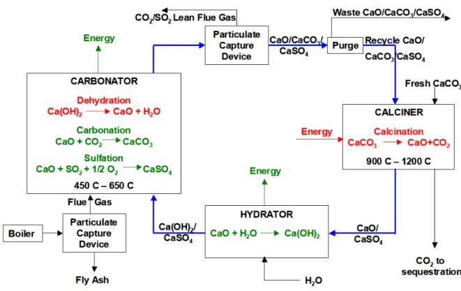
A process based on a carbonation/calcination cycle is currently developed. The main steps of the process are the following:
In a first fluidized bed, coal is burnt with the oxygen present in the fluidization gas: air. The resulting outlet gas is composed of mostly CO2, N2, O2 and SO2.
In a second fluidized bed, CaO is fluidized by the outlet gas of the previous reactor. Then, the following reactions occur:
CaO + CO2 → CaCO3 (1.1)
CaO + SO2+ 1/2O2 → CaSO4 (1.2)
In a third fluidized bed, CaCO3 is decomposed in a steam flow:
CaCO3 → CaO + CO2 (1.3)
Therefore, the CO2 is filtered at the outlet of the process.
The overall process is presented on figures 1.2 and 1.3.
Figure 1.2: Presentation of the reactions occurring in a CaO/CaCO3 chemical looping
This developing technology is currently being tested on a pilot plant in Darmstadt (Germany).
Figure 1.3: Summary of the CaO/CaCO3 chemical looping process
1.2.2
Pre-combustion
It involves the generation of syngas (carbon monoxide plus hydrogen (CO + H2)),
followed by the shift reactions to convert the CO to CO2. CO2 is then separated from
hydrogen, and the hydrogen can be burned in a turbine or used as fuel in a heater. Pre-combustion capture is often associated with integrated gasification combined cycle (IGCC) technology. Most studies suggest it is more cost-effective to use pre-combustion technologies with IGCC because the CO2can be captured at higher pressures compared
to post-combustion (IPCC 2005).
1.2.3
Oxy-fuel combustion
The technology in the demonstration stage involves the combustion of fuel in an oxygen-rich environment to dramatically increase the CO2 concentration of the resulting flue
gases. The increased CO2 concentration ( > 80%) of the flue gas stream facilitates CO2
separation. Oxyfiring produces lower emissions of nitrogen oxides (NOx) compared to air-blown combustion. After combustion, the flue gas can be captured and compressed, although some cleaning to remove contaminants is necessary before compression. Two options exist for oxy-fuel combustion:
Using a separation gas unit to extract O2 from air.
Using a chemical looping process based on the introduction of an oxygen carrier. This oxy-combustion process is presented in section 1.3.
As a conclusion on capturing the carbon dioxide technologies, the figure 1.4 presents a state of the art review of the promising CCS technologies.
Figure 1.4: ”Carbon sequestration technology road-map and program plan 2007” DOE /Office of Fossil Energy/NETL, April 2007
1.2.4
Storing the CO
2In 1996, at the Norwegian Sleipner site in the North Sea, the first geological storage of CO2 was installed. It involved the injection of one million tons of CO2 each year in a
deep aquifer. A European research project (Saline Aquifer CO2 Storage) was created
in 1998 to gather the experience earned on this pilot installation. In 2000, at Weyburn (Canada) an installation for CO2 geological storage in an oil reservoir was built. The
objective is to store 1.8 millions tons of CO2 each year for fifteen years. In 2001,
an international research program was created (IEA Weyburn CO2 Monitoring and
Storage Project) to study the efficiency of this plant. In the next few years, developing channels for CO2 storage are :
• storage in deep aquifers
• storage in depleted or declining oil and natural gas reservoirs • deep unmineable coal seams
But time is still necessary to ensure that those technologies allow CO2 to be stored
1.3
Chemical Looping Combustion technology
In this section, we will only focus on CLC technology as oxy-combustion technology. Among all alternative ways to use coal as a source of energy, Chemical Looping Com-bustion is a disruptive technology because the Oxygen is no more stored in a gaseous phase but in a solid phase. At the moment, it is still in development, but it is one of the most promising ways to burn coal and fulfill the environmental challenges of the next few years.
Chemical looping Combustion was first aimed to be used for pure CO2 production
(cf. Lewis and Gilliland (1954)). Its development really started thanks to the fossil industry in the 90’s to build a technology that would filter carbon dioxide release. While this development is still performed by the fossil industry, environmental industry is starting to study it, as a potential way to burn biomass or various waste.
A non-exhaustive list of companies funding research on CLC and academics partners working on this new technology is proposed at the end of this chapter.
1.3.1
General presentation of the process
In 1949, Lewis and Gilliland proposed a method to produce pure Carbon Dioxide re-sulting in a patent Lewis and Gilliland (1954).
”[...]the invention is concerned with the oxidation of carbonaceous material by means of solid oxidizing agents, such as metallic oxides as the source of oxygen. [...] A more specific object of this invention is to provide a process of the type specified which will permit oxidation of the carbonaceous material by metallic oxides, without contaminat-ing the carbon dioxide with inert gases, such as nitrogen.”
The basics of Chemical Looping Combustion (CLC) were set.
Ironically, since the last decade, this technology represents a major possible break-through in the capture of Carbon Dioxide exhaust of charcoal power plants. As intro-duced by Lewis and Gilliland (1954), the chemical-looping combustion involves the use of a metal oxide (MeOx) as an oxygen carrier which transfers oxygen to coal during combustion, thus avoiding direct contact between air and coal. Therefore, two inter-connected fluidized beds - a fuel reactor and an air reactor - are used in the process (cf. Figure 1.5). In the fuel reactor, the coal particle gasification allows the Metal Oxide reduction. In the air reactor, the Metal is oxidized by air. The element joining the two reactors can be a coal separation device or a loop seal.
Metal oxide
Coal
Ashes
Gas
Coal and MeOx
Air
Reactor
Reactor
Fuel
Loop
seal
Back
pass
CO2
Fuel
silo
Air supply
Fluidization steam
Cyclones
device
separation
Carbon
Lean air
Ashes
Fine ashes, steam, CO2
1.3.2
Reactors
The air reactor often consists in a circulating fluidized bed in which the reduced oxygen carrier is fluidized by air: Shuai et al. (2010) showed that the circulating fluidized bed technology might be a preferred candidate for CLC because it does not generate large bubbles that decrease the fuel conversion speed. The metal oxidation is an exothermic reaction. Indeed, most of the heat production in a CLC power plant comes from the air reactor. This reactor is needed to avoid contact between carbon and nitrogen. The metal oxidation changes flue gas into exhaust fumes by consuming part of its oxygen. Finally, this reaction does not produce any carbon dioxide or NOx due to the nitrogen contained in charcoal particles. A few Thermal NOx are expected because of the operating temperatures.
In the air reactor, the predominant reaction is:
M e + 1/2O2 → M eO (1.4)
The fuel reactor consists in a circulating fluidized bed in which the oxygen carrier particles and coal particles are fluidized by a mixture of steam and carbon dioxide. The coal particles are gasified and then oxidized by MeOx particles. It produces a large amount of carbon dioxide as a gaseous species, and reduced MeOx and ashes solid particles. This reaction is endothermic if the oxygen carrier is ilmenite and exothermic if the oxygen carrier is copper based. Then, in some configurations, the heat coming from the flue gas enable the reaction.
The gas phase at the outlet of the fuel reactor is expected to be composed mainly of carbon dioxide and steam so as to be able to capture a quasi-pure carbon dioxide flow by condensing the steam: more than 90% efficiency is expected.
In the fuel reactor, the predominant reaction is:
CxHy+ δM eO → αM e + βCO2 + γH20 (1.5)
Both reactors need excellent gas-solids contact and sufficient solids circulation rate. It is then of paramount importance to understand and control the hydrodynamics of the flow.
1.3.3
Cyclones
A centrifugal flow is separating the different solid phases. Each cyclone has a cut-off diameter. The role of the cyclones is to separate the different solid species (Coal, ashes, Metal Oxide). Indeed, the CLC process efficiency is based on the assumption that there is no fuel inside the air reactor. Another technological issue is the design of those cyclones that has to be sized to fit in a large scale power plant, considering the increase in the number of cyclones needed to filter the important mass flow rate of coal, ashes and oxygen carrier.
1.3.4
Carbon separation device
It is located between the two reactors and its role is to separate the coal particles coming out of the fuel reactor from oxygen carrier reduced particles. The challenge is to re-inject the oxygen carrier in the air reactor without any carbon particle.
The confidentiality and the economic stakes behind this element explain the lack of publications on its conception. In the confidential section (??), the carbon separation device developed by Alstom is presented.
1.3.5
Gasification process
When the coal particles arrive in the fuel reactor, it first devolatilizes. The non-negligible part of volatile species contained in coal particles is released. Then the gasification occurs producing a syn-gas composed of mostly CO and H2. Charcoal
particles are gasified in an environment of oxidizing gas (H2O + CO2) with rapid
removal of gasification products (CO, H2) already inside the particle phase. Dennis
et al. (2006) showed that gasification occurs in the Fuel Reactor expected operating conditions.
1.3.6
Oxygen carrier selection
Lots of experiments on Metal Oxide as oxygen carriers were performed to determine the best candidates for CLC utilization. This work regroups an important number of industrial partners and researchers. It is due to the fact that CLC technology is new and only a few pilot plants were operational in the early 00’s.
The oxygen carrier needs to fulfill restrictive conditions to be considered as a good candidate for CLC:
• Be stable under repeated oxidation/reduction cycles and offer mechanical resis-tance to friction: the oxygen carrier will be used for thousands of hours before being replaced.
• Be fluidizable and resistant to agglomeration: the circulation of both solid species is necessary from the beginning to the end of the process.
• Be environmentally benign in case of massive use in coal industry. This criterium is restrictive because the toxicity of Metal Oxides is difficult to characterize.
• Be economically feasible: the technology has to be cheap enough to stay under the CO2 exhaust market.
Richter and Knoche (1983) first study on oxygen carriers showed the reversibility of combustion processes in CLC-like units. Later an important number of worldwide research teams focused on the research of the best oxygen carrier regarding the previ-ous four physical, environmental and economical constraints.
Lots of experiments were performed on gaseous, solid and liquid fuels. Villa et al. (2003) from Politecnico di Milano, Readman et al. (2006) and Kolbitsch et al. (2009) performed experiments on Nickel based oxygen carriers. In 2004, Adanez et al. (2004) from Instituto de Carboquimica (CSIC) in Zaragoza, experimented on oxygen carri-ers based on Cu, Fe, Mn, or Ni oxides on Al2O3, sepiolite, SiO2, TiO2, or ZrO2 for CLC. Shen et al. (2010) from South East Nanjing worked on Iron ore as oxygen carrier.
Eyring et al. (2011) performed experiments with Copper Oxide as carrier and Coal as Fuel. It showed that ’the gasification rate of carbon is no longer a major constraint in the sizing of the fuel reactor as the burnout times for carbon are comparable or smaller than the decomposition times of CuO’. The main advantage of copper oxide is that its reaction with coal is exothermic. The main drawbacks are its price and toxicity.
Adanez et al. (2004) conclude that ilmenite was a good oxygen carrier regarding its price, reactivity and performance in fluidized beds.
It is also of paramount importance to determine the optimum conditions for the conversions of the fuel reactor and the air reactor: the mass ratio of the Oxygen carrier has to be settled regarding it residence time in each reactor.
Ksepko et al. (2010) in the Institute for Chemical Processing for Coal of Poland showed that the reaction profile was changed by the presence of H2S but there was no
effect on the reaction rate due to the presence of H2S in synthesis gases.
Ryu et al. (2004) from Korea Institute of Energy Research performed experiments on a 50 kWth pilot plant that showed continuous oxidation-reduction cycles and the absence of NOx at the outlet of the oxidizer. Hossain and de Lasa (2008) from Chemical Reactor Engineering Center at the University of Western Ontario, published a review on the work already done on Oxygen carrier selection.
Based on Adanez et al. (2004) work, ilmenite was selected to be the oxygen carrier for the 1 M W th CLC pilot plant of Darmstadt.
Ilmenite characteristics
Ilmenite is a titanium-iron oxide mineral: F eT iO3. It is known to be a black sharp,
opaque crystal. Its density is between 4.5 and 5. Its magnetism is naturally weak but it will always becomes magnetic if heated Cui et al. (2002). World resources of ilmenite total more than 1.2 billion tons, as mentioned in the following report Survey (2006).
Even when ground, the shape of ilmenite particles is uneasy to define. Knowing the influence of the shape (sphericity) of the particle on the drag force and on the granulometric analysis, work has been done on the study of the grinding of particles Berthiaux and Dodds (1999). It is a major issue to control the distribution of the sizes of the particles that are fluidized to be able to predict the hydrodynamics of the process in order to size the power plants.
In 1962, Ciborowski and Wlodarski (1962) first studied the electrostatic effects in fluidized beds:
”The electric charges which accumulate on solid particles may cause:
• 1. the adhesion of a layer of solid particles to the walls of the fluidizing equipment. • 2. the agglomeration of particles into larger aggregates.
• 3. the change of a fluidized bed into a channeling bed.
Between the metal elements which are in contact with the fluidized bed there may arise considerable potential differences, reaching even more than 15 kV.”
At the moment, the author did not find any review dealing with the effect of mag-netism on the hydrodynamic, but it is well admitted that electric phenomena can alter the hydrodynamic of fluidized beds.
In CLC processes, this property can also be a way to separate reduced metal oxide particles from coal particles in the carbon separation device. No tests have yet been performed to see if the magnetic property of ilmenite would be sufficient to do so.
1.3.7
CLC with gaseous fuels
Ishida and Jin (1994); Jin and Ishida (2002) from Tokyo Institute of Technology pro-pose CLC as a solution to solve environmental issues of industrial energy production. Experiments on a Metal Oxide have been performed with gaseous fuels. It showed good reactivity and mechanical strength.
Experiments performed by Lyngfelt et al. (2001) at Chalmers University of Tech-nology showed that using interconnected fluidized beds was promising for CLC tech-nologies. 100 h of experiments on a pilot scale plant (12 m high Fuel Reactor, 35 ton coal/day) have been performed by Lyngfelt et al. (2004). It showed the efficiency of the process: 99.5% of fuel conversion (gaseous fuel), 100% of CO2 separated, no loss
in particle reactivity during cycles.
Kronberger et al. (2005) work on a dual-fluidized bed reactor system representing a 10-kW CLC prototype. A scaled flow model was built and investigated: gas veloci-ties and reactors designs were parameters, while solids circulation rate and gas leakage between the reactors as well as static pressure balance and residence time distribution of gas and particles were measured. Results showed that the solids circulation rates were sufficient and the gas leakage could be decreased to very low values.
1.3.8
CLC with solid and liquid fuels
In 2008 , 2800 h of operational experience were performed by Lyngfelt et al. on multiple CLC units. Many fuels (solid and liquid) and oxygen carriers were tested. It then was showed that:
• Solid fuels react after a gasification step.
• It is a major issue to ensure that no charcoal particles arrive in the AR.
• Gasification reaction is slow implying a large solid inventory in the fuel reactor. • Ashes can influence the MeOx lifetime.
In 2010, experiments performed on the 100 kWth Vienna University of Technology prototype that gave interesting results on the influence of Oxygen carriers circulation rate, reactor temperature or fuel gas load. The influence of the solid inventory is planned to be studied. Ilmenite was proven to be a good oxygen carrier regarding its price, reactivity and performance in fluidized beds. Nevertheless, it provokes a very endothermic reaction reducing thus the main efficiency of the process.
1.3.9
Hydrodynamics issues
Circulating flow rate
A mixing of two different solid species is coexisting in the Fuel Reactor: on one hand, large and dense oxygen carriers particles and on the other hand smaller and lighter carbon particles. Fabre (1995) or Batrak (2005) Ph.D works showed the complexity of the prediction and understanding of the main hydrodynamic of such a flow. Batrak modeled the experiment of Fabre in which was introduced a binary mixture of:
• Large and dense particles with a terminal settling velocity twice bigger than the fluidization gas velocity.
• Small and light particles with a terminal settling velocity inferior to the fluidiza-tion gas velocity.
It was shown that both large and small particles were able to circulate through the bed. The main characteristic mechanisms triggering the circulation of the large particles are not yet understood. One of the purpose of this Ph.D work is to propose some explanations.
Production of gaseous species
Another specific issue of CLC process comes from the reaction between two solid species. Indeed, in classical gas-solid circulating fluidized beds, coal is oxidized by a gaseous phase: there is a change of density of the gas phase during the reaction, but hardly no production of gas inside the reactor. In solid-solid combustion, the produc-tion of gas inside the flow can be of the order of magnitude of the fluidizaproduc-tion gas flux. There is no experimental data on the effect of this gas production on the circulation of solids inside the reactor available yet.
Nevertheless, the resulting increase of the gas phase velocity inside the reactor is ex-pected to modify the global hydrodynamics of the bed. This work aimed at investi-gating and modeling the influence of this phenomenon in order to take it into account in the design of the CLC pilot plant of Darmstadt. This pilot plant is presented and described in Chapter ??.
Scaling up
A few correlations exists to perform the scaling up of Circulating Fluidized Beds pilot plants to commercial scale. But it is known that the scaling up of fluidized bed is a tricky matter. Kronberger explained that the ratio between the solid mass flow rate and fuel reactor inventory must remain constant during the scaling up. So does the inter-phase mass transfer coefficient and the dimensionless reaction rate (cf. Kron-berger et al. (2004)).
Recent studies performed by Parmentier et al. (2008) showed that the issues of fluidization of Geldart A particles at experimental scale can be found with Geldart B particles at commercial scale. This effect has to be taken into account before consid-ering the scaling up of the pilot plant.
1.3.10
Review of pilots or experimental CLC units
In the Table 1.3.10, the different existing pilot plants of CLC are presented. The information is likely to change quite quickly because of the interests and expectations around this technology.
Lo cation Unit MeOx/CaO test ed Op eration F uel Ref hours Chalmers 10 kW NiO, F e2 O 3 1355 natural gas Lyngfelt and Th unman (2005) KIER, S k orea 50 kW NiO, CoO 28 natural gas Ryu et al. (2004) CSIC, Spain 10 kW NiO, CuO 140 natural gas Adanez et al. (2006) Chalmers 300 W NiO, M n3 O4 559 natural gas Johansson et al. (2006) F e2 O3 , Ilmenite syngas CSIC, Spain 500 W NiO, CuO 660 natural gas Adanez et al. (2008) Chalmers 10 kW Ilmenite 50 coal, p etcok e Berguerand and Lyngfelt (2008) Daejong, S Korea 1 kW NiO + F e2 O3 ? C H4 Son and Kim (2006) Vienna T ec hn. Univ. 120 kW NiO, Ilmenite 50 natural gas, CO, H 2 Pr¨ oll et al. (2008) Darmstadt 1 MWth Ilmenite/CaO -coal -OSU 2.5 kWth, 25 kWth -coal, syngas Lee et al. (2001) 250 kWth IFP 10 kWth NiAlO -liquid/solid fuels Chandel et al. (2009) Alstom 65 kWth MeOx 100 h natural gas Alstom, windsor 3 MWth CaO -naturalgas, coal ICSET, Ken tuc ky 10 kW NiO -solid Cao et al. (2004) South East Univ 1 kW -Song et al. (2008) Nanjing, Chine
1.3.11
Companies and institutions working on CLC
• Funding for research on CLC are coming from multiple energy companies that are interested by Chemical Looping Combustion intrinsic CO2 capture. For
ex-ample,
ALSTOM Power Systems, Air Liquide, IFP energies nouvelles, Sintef, Vattenfall, Shell, Total S.A., Gaz de France, EDF...
• National and International Institutions are funding projects such as: CO2
Cap-ture Project (CCP), GRACE project, ENCAP project, ECLAIR, CASTOR...
• Academic partners working on the subject are among others: Universit´e Paul Sabatier (France), Institut National Polytechnique de Toulouse (France), Chalmers University (Sweden), Technische Univ. Darmstadt (Germany), CSIC (Spain), NETL (USA), University of Western Ontario (Canada), Ohio State University (USA), Vienna University of Technology (Austria), Southeast University (China), Cambridge University (UK), Univ. di Napoli Federico II (Italy), Hamburg Univ. of Technology (Germany), Univ. Henri Poincar´e (France), Korean Institute of Energy (Korea)...
R´
esum´
e du Chapitre 2
Le chapitre 2 pr´esente la mod´elisation des ´ecoulements r´eactifs poly-solides.
Depuis les ann´ees 70, des scientifiques ´etudient le comportement des lits fluidis´es. De nombreuses ´etudes ont ´et´e effectu´ees sur des installations exp´erimentales ou indus-trielles. Ainsi, les diff´erents comportements de ces lits ont ´et´e class´es en tenant compte des caract´eristiques des particules transport´ees, de la vitesse et de la composition du gaz de fluidisation et en fonction de la g´eom´etrie ´etudi´ee.
Au cours des ann´ees 80, des approches empiriques ont ´et´e developp´ees pour dimen-sionner des lits fluidis´es industriels. En raison des limitations de ce type d’approches, des scientifiques ont travaill´e `a mod´eliser le mouvement des particules transport´ees par un gaz. Ainsi, plusieurs approches sont n´ees:
• Euler-Lagrange: la phase gazeuse est mod´elis´ee `a l’aide des ´equations de Navier-Stokes et l’´equation du mouvement de chaque particule est r´esolue. Cette ap-proche permet de r´esoudre tr`es pr´ecis´ement l’´ecoulement autour de chaque par-ticule mais a l’inconv´enient d’ˆetre tr`es coˆuteux.
• Euler-Euler: la phase gazeuse est mod´elis´ee `a l’aide des ´equations de Navier-Stokes. La phase solide est mod´elis´ee en adaptant la th´eorie cin´etique des gaz en prenant en compte la pr´esence d’un gaz interstitiel. Cette approche n´ecessite la mod´elisation des couplages interfaciaux: train´ee, collisions... mais pr´esente l’avantage d’ˆetre beaucoup moins coˆuteuse que l’approche pr´ec´edente.
L’approche Euler-Euler de type mod`ele `a N-fluides a donn´e de bons r´esultats con-cernant la mod´elisation de lits fluidis´es de particules de classe B selon Geldart. En revanche, certaines ´etudes ont montr´e les limites de cette approche lors de l’´etude de lits fluidis´es de particules de classe A. Il a ´et´e montr´e qu’il est n´ecessaire de d´evelopper des mod`eles de sous-mailles pour mod´eliser correctement la train´ee exerc´ee par le gaz sur ces particules. Il a ´egalement ´et´e montr´e que la taille de la g´eom´etrie peut avoir une influence cons´equente sur la capacit´e des mod`eles `a pr´edire l’hydrodynamique des LFC.
En ce qui concerne l’´etude de lits fluidis´es d’un m´elange binaire de particules, des ´etudes ont montr´e que l’approche Euler-Euler pr´edisait correctement l’hydrodynamique des lits fluidis´es bouillonnants. Des ´etudes concernant la s´egr´egation radiale et axiale ainsi que les profils radiaux de vitesses et de flux circulant de solide ont ´et´e men´ees. Ces ´etudes num´eriques et exp´erimentales sont souvent faites sur des g´eom´etries `a l’´echelle exp´erimentale. Il existe peu de simulations tridimensionnelles d’exp´eriences `a l’´echelle du pilote industriel.
Ce travail a pour objectif de valider l’approche Euler-Euler impl´ement´ee dans NEP-TUNE CFD V1.08@Tlse sur des configurations exp´erimentales mono-solide puis bi-solide afin d’ˆetre en mesure de participer au dimensionnement d’un pilote de type CLC via des simulations 3D instationnaires isothermes poly-solides et r´eactives.
La deuxi`eme partie de ce chapitre pr´esente la mise en place des equations de trans-port des phases gazeuses et solides. Ensuite, sont pr´esent´es les lois de fermeture des ´equations impl´ement´ees dans NEPTUNE CFD V1.08@Tlse ainsi qu’un mod`ele de r´eaction permettant de prendre en compte la production locale de gaz due `a la combustion du charbon avec l’ilmenite.
Chapter 2
CFD modeling of poly-solid
reacting flows
2.1
Introduction to circulating fluidized beds
2.1.1
Behavior of circulating fluidized beds
The circulating fluidized beds are utilized at industrial scale since the 40’s in the frame of Fluid Catalytic Cracking. It means that lots of experience and experimental data have been accumulated about their behavior.
Geldart’s Classification
The prediction of the behavior of a fluidized bed first requires to know the character-istics of the fluidized particles. In 1973, Geldart (1973) proposed a classification of the particles regarding their size and density. The conclusion of his study was:
”The behavior of powders fluidized by gases falls into four categories characterized by density difference (ρp− ρg) and mean size. Powders in group A exhibit dense phase
ex-pansion after minimum fluidization and prior to the commencement of bubbling; those in group B bubble at the minimum fluidization velocity; those in group C are difficult to fluidize at all and those in group D are of large size and/or density and spout readily. A criterion which distinguishes between groups A and B has been devised and is shown to agree well with published data. It also predicts that a change in pressure and/or gas viscosity may cause a change in the behavior of particles. A tentative criterion is also suggested for group D.”
In 2007, Yang (2007) adapted this classification (cf. 2.1) of powders to make it valid for powders with different properties and fluidized at different pressures and temperatures. Depending on the fluidization velocity, the particles of each Geldart group form a bubbling, circulating ... fluidized bed. Kunii and Levenspiel (1991) proposed a dia-gram summarizing the different sort of fluidized beds regarding the particle class and the fluidization velocity (cf. Figure 2.2).
Evolution of the volume fraction of solid
Considering the axial profiles, most of the existing experiments showed a ”S-shape” solid fraction curve for the circulating fluidized beds due to:
10−1 100 101 102 103 104 105 106 102 103 104 Ar = d p 3ρ g (ρp − ρg) g / µg 2 ρ * = ( ρ p − ρ g ) / ρ g Border AB Geldart Border BD Geldart
Border AC Geldart (Yang 2006)
A
B
D
C
Figure 2.1: Geldart classification of powders modified by Yang
Fixed bed D (spouting) Channeling Geldart Smooth Bubbling Pneumatic transport Fast fluidization Turbulent−churning Increasing gas velocity bubbles Exploding
Fine solids Large solids
C A B
Figure 2.2: Progressive change in gas solid contacting with change in the gas velocity
• at the bottom: the short dense zone with αs= from 0.2 to 0.4
• in the upper region: the solid volume fraction decreases until αs = from 0.02 to
0.05.
Mixing and segregation
The mixing and segregation of solids in a CFB strongly depends on the operating point studied. Nevertheless, a few general behaviors can be outlined:
• Vertical segregation is not likely to appear in fast fluidized beds: where the flu-idization velocity is larger than the minimum fluflu-idization velocity of the particles (Kunii and Levenspiel (1991)).
• A significant radial segregation of the mean diameter is observed in the riser (Mathiesen et al. (1999)).
• For binary mixture of particles, segregation occurs when the fluidization velocity comes close to the minimum fluidization velocity of largest/heaviest particles (Chiba et al. (1980)).
2.1.2
Numerical modeling of CFB
In the late 60’s, scientists such as Wen and Yu (1966) started to develop theoretical tools to describe the motion of particles inside a gas phase.
Since the 80’s, empirical approaches have been developed to predict the behavior of CFB’s hydrodynamic (Schoenfelder et al. (1994) or Kunii and Levenspiel (1991)). The major drawback of this modeling approach is that it cannot be extended to any other operating point. Its use is then very limited.
The Eulerian modeling of the dispersed phase in dilute two-phase flows using mod-els obtained in the framework of Tchen’s therory of discrete particles supended in homogeneous turbulence was achieved and validated by Elghobashi and Abou-Arab (1983), Chen and Wood (1986) and Simonin and Viollet (1990). The modeling of dense gas-solid flows necessitates closures derived in the frame of the kinetic theory of dry granular flows (Lun et al. (1984), Jenkins and Mancini (1989),Ding and Gidaspow (1990)). Then, different approaches have been proposed to model the interaction be-tween particles and turbulence and particles collisions (Derevich and Zaichik (1990), Reeks (1991), Simonin (1991)).
The Eulerian-Eulerian modeling gave relevant results for the simulation of fluidized beds: Enwald et al. (1999), Ferschneider and Mege (1996), Bouillard et al. (1991). The two-fluid modeling has been complemented by Balzer and Simonin (1994) and vali-dated on multiple experimental set up for particles of Geldart B type: Patureaux and Barthod (2000), Neri and Gidaspow (2000), Andreux et al. (2003),Taghipour et al. (2005)... The order of magnitude of the height of the bed or the pressure gradient estimated compared quite well with the experiments.
When the influence of the size of the particles, or the mixing of solid particles with different characteristics is investigated, weaknesses of this modeling appear. The application of this method to bubbling or turbulent fluidized beds of fine Geldart A
particles leads to an overestimation of the bed expansion: (McKeen and Pugsley (2003), Zimmermann and Taghipour (2005)). Recently, Parmentier et al. (2008) showed that this overestimation might not be due to the van der Waals interaction only but to the refinement of the grid of the studied fluidized bed. Indeed, simulations on large dense fluidized bed with Geldart B type particles with a sufficiently refined grid predict the right bed height. Due to the cost of such simulations, it has become necessary to develop sub-grid models to predict the fine scale structures occuring in a CFB (Agrawal et al. (2001), Andrews IV et al. (2005) Igci et al. (2008)).
2.1.3
CFB with a binary mixture of solid
In the 80’s, Squires et al. (1985) and Yates and Newton (1986) showed that adding fines to a monodisperse fluidized bed promote uniform fluidization. In 1991, Formisani (1991) performed experiments on dense fluidized beds of a binary mixture of particles with the same density. The conclusion was: ”The considerable lowering of minimum fluidization velocity that the addition of a small amount of fines can promote in a bed of coarser particles can be explained by the resulting voidage reduction, which causes a corresponding increase in interstitial gas velocity.” There is no mention of the possible influence of the collisions on this phenomena.
Other work on binary mixtures of particles have focused on fluidized beds and showed that both Euler-Euler and Euler-Lagrange approach can predict the axial seg-regation of the more massive particles towards the bottom of the riser (Mathiesen et al. (2000a), Mathiesen et al. (2000b), Huilin and Gidaspow (2003)). For the radial seg-regation, Benyahia (2008),He et al. (2009) or Hirschberg and Werther (1998) showed that the massive particles preferentially segregates to the wall. Moreover, it showed that increasing the solid loading tends to decrease the species segregation.
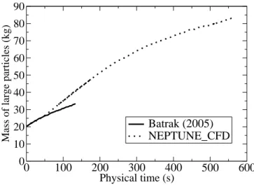
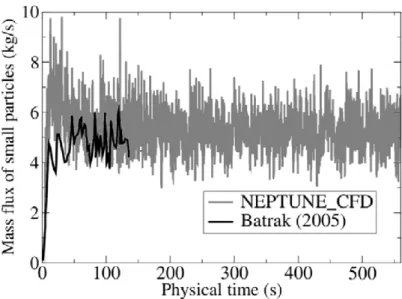
Fabre (1995) experimentally studied a circulating fluidized bed of a binary mixture of sand. The study showed that a binary mixture of solid fluidized bed can be a circulat-ing fluidized bed, even if the terminal settlcirculat-ing velocity of one of the two solid species is twice the fluidization velocity.
Batrak et al. (2005) showed that Eulerian-Eulerian modeling can predict this trend. But there is still an underestimation of the circulation of large particles through the bed.
2.1.4
CFD modeling of CLC processes
With such a young technology as CLC, there are only a few recent experimental data that can be used to validate its modeling. A few experiments have been performed specifically to design CLC power plants:
• Experiments on cold flow model circulating fluidized beds aiming at studying the main hydrodynamics phenomena due to the poly-solid flow characteristics.
• Small scale CLC experiments in order to investigate the reaction between the oxygen carrier and the charcoal.
For a few years, some experiments on the whole process have been performed at laboratory scale. Most of them aims at studying the process expected efficiency, the
pollutant emissions or the main hydrodynamics parameters such as the outlet mass flow rate of each species, the pressure profile along the reactors, the mass fluxes pro-files...
The local hydrodynamic is seldom studied in such experiments because of the lack of non-intrusive measurement systems able to estimate important unknown parameters of the process such as for example the local production rate of gas inside the bed or the evolution of the volumetric fraction of each phase. In this area, CFD is needed to predict and understand the physical phenomena occurring in the main elements of the process: the fuel reactor, the carbon separation unit, the cyclones or the air reactor.
CFD developers are focusing on validating this modeling on cold flow experiment and on combustion experiments before modeling the entire CLC unit. Studies are mainly focused on:
• The combustion: the description of the kinetic mechanisms is complicated due to the composition and shapes of coal or oxygen carrier particles.
• The hydrodynamics: the fuel reactor is for example an unsteady three dimen-sional poly-solid reactive multiphase flow.
• The cyclones and the air reactor are better known because of their use in CFB units. Nevertheless the modeling of this kind of experiment at pilot scale remains a challenge.
Hydrodynamic studies of CLC working with gaseous fuel has successfully been per-formed and validated by Deng et al. (2008), Mahalatkar et al. (2011), Shuai et al. (2010), Kruggel-Emden et al. (2011),Jung and Gamwo (2008), Xu et al. (2007), Balaji et al. (2010), Rifflart et al. (2011).
At the moment, published simulations or experiments on the hydrodynamic study of a reactive circulating fluidized bed of a binary mixture of particles lacked.
Then, some points remain to be investigated:
Is Eulerian-Eulerian modeling able to predict the hydrodynamics of bisolid circulating fluidized beds of CLC plants ?
What is the source of the increase of solid circulation inside CFB’s caused by polydispersion ?
Is there an influence of the local production of gas inside the bed on the global hydrodynamics of a circulating fluidized bed ?