En vue de l'obtention du
DOCTORAT DE L'UNIVERSITÉ DE TOULOUSE
Délivré par :
Institut National Polytechnique de Toulouse (INP Toulouse)
Discipline ou spécialité :
Energétique et Transferts
Présentée et soutenue par :
M. ZIAD HAMIDOUCHE
le mardi 21 février 2017
Titre :
Unité de recherche :
Ecole doctorale :
Modeling and numerical simulation of coupled reactive fluidized beds in a
Chemical Looping Combustion system
Mécanique, Energétique, Génie civil, Procédés (MEGeP)
Institut de Mécanique des Fluides de Toulouse (I.M.F.T.)
Directeur(s) de Thèse :
M. OLIVIER SIMONINMME ENRICA MASI
Rapporteurs :
M. GILLES FLAMANT, CNRS FONT ROMEU M. LOUNES TADRIST, AIX-MARSEILLE UNIVERSITE
Membre(s) du jury :
1 M. GERALD DEBENEST, INP TOULOUSE, Président
2 M. MAHDI YAZDANPANAH, TOTAL REFINING, Membre
2 Mme ENRICA MASI, UNIVERSITE PAUL SABATIER, Membre
2 Mme PERRINE PEPIOT, CORNELL UNIVERSITY EU, Membre
2 M. OLIVIER AUTHIER, EDF CHATOU, Membre
Remerciements
Ce présent travail de thèse s’est déroulé en trois ans à l’Institut de Mécanique des Fluides de Toulouse (IMFT). Il a été dirigé par Enrica Masi et Olivier Simonin et défendu en date du 21 Février 2017 devant un jury constitué de huit membres, envers qui je réitère mes remerciements pour avoir accepté de juger cette thèse. Une modélisation et des simulations numériques de la combustion en boucle chimique ont constitué la partie centrale de ce travail. Un travail théorique (modélisation et sim-ulation) a aussi été réalisé sur la combustion du méthane en lit fluidisé dense. Cette très brève présentation de la thèse ne permet surtout pas de rendre compte de tout son déroulement et de son aboutissement. Ainsi, ceux qui souhaitent s’informer de l’apport scientifique de ce travail, sont tout simplement invités à lire ce manuscrit. Par contre, si vous êtes curieux de savoir comment cette thèse a pu être réalisée, vous êtes priés de continuer à lire ces quelques lignes !
On dit que l’argent ne fait pas le bonheur mais sans le financement de l’Union Eu-ropéenne dans le cadre du projet européen SUCCESS, cette thèse n’aurait pas pu être proposée et je n’aurais peut-être pas pu faire ma thèse à l’IMFT. Vous l’avez compris, loin d’être perçu comme un travail pénible, et bien qu’elle puisse parfois l’être, une thèse a été un bonheur pour moi !
Mais l’argent ne fait pas tout non plus ! Je parle ici de toutes les personnes qui ont permis que cette thèse ait pu voir le jour. Je pense en premier lieu à mes encadrants pour qui je réserve ces quelques mots pour exprimer mon profond respect et ma vive gratitude. Je m’adresse à toi, Enrica, pour te dire simplement que je suis ravi de t’avoir connu. J’avoue qu’au début de la thèse, j’avais peine à suivre ton inces-sante recherche de la perfection et ton souhait d’aller dans le détail des phénomènes scientifiques couplés de combustion hétérogène, de transfert thermiques et de trans-fert massiques que nous avons souhaité élucider. Au terme de cette thèse, je me rend compte que tu m’as appris l’endurance et la persévérance dans la recherche scientifique, sans quoi je n’aurais pas pu aller au bout de ce travail de thèse. Pour ça, je te serai éternellement reconnaissant. Merci également à toi Olivier. Tu m’as surpris par ta riche expérience. Durant cette thèse, je n’ai pas cessé d’apprendre de ton expérience en génie des procédés, en écoulements gaz-particules et en simula-tion numérique. Les réunions des Mardis à l’INPT m’étaient d’une aide précieuse à l’avancement de mes travaux et souvent, à la sortie de ces réunions, j’occupais mes quelques 5 à 10 min d’attente du bus à destination de Ramonville, à réfléchir sur les explications scientifiques que tu avançais au cours de la réunion, en me disant
ii
sincèrement que j’étais chanceux de t’avoir eu comme encadrant. Sans toi, cette thèse serait-elle de la même qualité qu’elle l’est aujourd’hui? Sûrement pas ! Les deux autres formidables personnes que je souhaite également remercier sont Pascal Fede (Groue PSC) et Hervé Neau (Service Cosinus). L’un comme l’autre ont pu très favorablement contribué à ce travail de thèse. J’ai toujours appré-cié les multiples discussions que j’ai eues avec Pascal concernant, en particulier, l’hydrodynamique des systèmes CLC. Pour sa part, Hervé a été comme la réponse à toutes mes questions concernant le volet numérique de ce travail, à commencer par la génération des maillages et à finir par le "débuguage" !
Presque tout est donc mis en place afin que cette thèse soit menée à bien et à terme. Pour que je puisse dire "Tout", il faudrait que je cite l’apport précieux des différents services administratifs de l’IMFT. Ici, je pense tout particulièrement à remercier chaleureusement notre gestionnaire de groupe, Florence Colombiès, pour sa disponibilité et son efficacité à répondre à mes questions relatives aux procédures de renouvellement du titre de séjour et aux procédures liées à mes déplacements professionnels en Europe au cours de cette thèse. Grâce à toi, Florence, je peux dire que tout est mis en place pour une thèse réussie ! Merci beaucoup.
Au commencement de cette thèse, mes encadrants avaient eu l’ingénieuse idée de me faire "roder" à la modélisation et à la simulation des écoulements gaz-particules réactifs, en commençant par un travail d’investigation théorique et numérique de combustion du méthane dans un lit fluidisé dense. C’est au cours de cette étude préliminaire que j’ai connu une personne sympathique et joyeuse. Il s’agit de Re-naud Ansart du Laboratoire de Génie Chimique (LGC) de Toulouse. Ses interven-tions ont constitué une précieuse contribution à cette étude. Merci Renaud ! Une bonne thèse, c’est aussi une bonne ambiance de travail. Cette ambiance est le résultat d’une coexistence fort conviviale avec mes collègues dans le groupe PSC. Pour ça, j’aimerais remercier les personnes suivantes: François Audard, mon col-lègue du bureau, pour son aide qu’il m’a apporté tout au long de cette thèse, une aide dont j’ai surtout bénéficié après que je sois habitué à son fort accent toulousain ! Ibrahima Thiam, pas très bavard, mais avec qui j’ai toujours eu du plaisir à partager mes reflexions et à accueillir les siennes ! Merci également à Solène Chevrier, à Nico-las Reuge, à Lokman Bennani, à Gorkem Oztarlik, à Oliver Scorsim et à Guiquan Wang, qui tous, ont contribué à ce que je me sente tout simplement heureux d’avoir fait ma thèse à l’IMFT.
Je dédie ce travail à mes parents car chaque pas que je fais, est tout simplement grâce à eux. Je le dédie aussi à ma chère épouse, qui tout au long de mon parcours de thésard, a su m’épauler et m’encourager. Elle me dit souvent qu’elle est fière de moi, mais pour son soutien et sa présence à mes cotés, c’est plutôt moi qui suis fière d’elle !
Abstract
Keywords: chemical looping combustion, oxygen carrier, fluidized beds,
heteroge-neous reactions, shrinking core model, methane combustion.
In this work, reactive unsteady three-dimensional numerical simulations of a Chem-ical Looping Combustion (CLC) plant are performed. The plant is a 120 kWthpilot
working with CaMn0.9Mg0.1O3−δ as selected oxygen carrier. Numerical simulations
are performed by NEPTUNE_CFD code using an Euler-Euler approach which computes both the gas and the solid phases in an Eulerian fashion accounting for specific closures in order to model interphase mass, momentum and energy trans-fers. Reduction and oxidation heterogeneous (i.e. gas-solid) reactions are modeled by means of a grain model (shrinking core model in the grain) accounting for both the competing mechanisms of chemical reaction at the particle internal surface and gaseous diffusion through the product layer. Results from numerical simulations are validated against experimental measurements and analyzed in order to gain insight in the local behaviour of the reactive gas-particle flow in the CLC system. The theoretical/numerical tool developed in this work will be used for design upgrade recommendation in the stage of scaling-up from pilot to industrial facilities.
Résumé
Mots-clé : combustion en boucle chimique, transporteur d’oxygène, lits fluidisés,
réactions hétérogènes, modèle à cœur rétrécissant, combustion du méthane.
Dans cette thèse, des simulations numériques tridimensionnelles instationnaires d’une installation expérimentale de combustion en boucle chimique sont réalisées. Le pilote expérimental, d’une puissance de 120 kWth, utilise un matériau perovskite,
à base de Ca-Mn, comme transporteur d’oxygène (CaMn0.9Mg0.1O3−δ). Les
simu-lations numériques sont réalisées par le code NEPTUNE_CFD, selon une approche Euler-Euler pour les deux phases (solide et gazeuse), avec des modèles de ferme-ture spécifiques pour modéliser les transferts de masse, de mouvement et d’énergie.
iv
Les réactions hétérogènes (i.e. réactions gaz-solide) de réduction et d’oxydation sont décrites au moyen d’un modèle à cœur rétrécissant dans le grain, qui prend en compte les mécanismes compétitifs dans le processus global de réaction gaz-solide: réaction chimique à la surface interne des particules, diffusion à travers la couche de produits et transfert externe autour des particules. Les résultats des simulations numériques sont validées avec des mesures expérimentales et analysées afin de mieux comprendre le comportement local/instationnaire de l’écoulement gaz-particules réactif dans ce système de combustion en boucle chimique. L’outil théorique/numérique développé dans ce travail sera utilisé pour le dimensionnement d’une unité pilote à l’échelle des installations industrielles.
Contents
Nomenclature vii
1 Introduction 1
2 Generalities on Chemical looping combustion 3
2.1 Introduction . . . 4
2.2 Carbon capture technologies . . . 4
2.2.1 Post-combustion capture . . . 5
2.2.2 Pre-combustion capture . . . 5
2.2.3 Oxy-fuel combustion capture . . . 5
2.3 Chemical looping combustion technologies . . . 7
2.3.1 Process overview . . . 7
2.3.2 Reactor configurations for CLC of gaseous fuels . . . 9
2.3.3 Oxygen carrier fundamentals . . . 11
2.4 Reaction schemes and kinetics in CLC systems . . . 21
2.4.1 Reaction schemes . . . 21
2.4.2 Gas-solid reaction kinetics . . . 23
3 Modeling gas-particle reacting flows in fluidized beds 29 3.1 Introduction to circulating fluidized beds . . . 30
3.2 Unsteady three-dimensional modeling approaches . . . 32
3.2.1 Euler-Lagrange approaches . . . 33
3.2.2 Euler-Euler approaches . . . 35
3.3 Modeling reactive gas-particle flows . . . 36
3.3.1 Gas phase modeling . . . 37
3.3.2 Dispersed phase modeling . . . 40
4 Simulation of dense fluidized bed reactors 51 4.1 Introduction . . . 52
4.2 Brief description of the experimental campaign . . . 52
4.3 Modeling approach . . . 54
4.3.1 General presentation . . . 54
4.3.2 Methane-air mixture combustion modeling . . . 55
4.3.3 Thermal radiation model . . . 57
4.3.4 Local mean phase temperature determination . . . 58
vi Contents
4.4.1 Configuration and mesh . . . 59
4.4.2 Simulation cases . . . 60
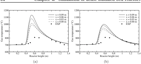
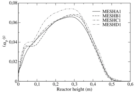
4.4.3 Results and discussions . . . 62
4.5 Conclusion . . . 76
5 Simulation of chemical looping combustion processes 77 5.1 Introduction . . . 78
5.2 Description of the experimental set up . . . 78
5.3 Modeling approach . . . 80
5.3.1 General presentation . . . 80
5.3.2 Evolution of the particle properties . . . 81
5.3.3 Modeling the interphase mass transfer . . . 83
5.3.4 Balance of gas mixture species . . . 84
5.3.5 Modeling the interphase enthalpy transfer . . . 84
5.3.6 Local mean phase temperature determination . . . 85
5.3.7 Heterogeneous gas-solid reaction . . . 86
5.3.8 Validation of the gas-solid reaction modeling . . . 93
5.4 Numerical simulation . . . 95
5.4.1 Configuration and mesh . . . 95
5.4.2 Initial conditions . . . 96
5.4.3 Boundary conditions . . . 97
5.4.4 Simulation cases . . . 97
5.4.5 Results and discussions . . . 98
5.5 Conclusion . . . 115
6 Thesis overview and perspectives 117
Appendix 123
Nomenclature
Latin Symbols
CA Molar concentration of species A [ mol m−3 ]
CD Drag coefficient [ − ]
Cpk Specific heat of the phase k [ J kg
−1 K−1 ] Dg Turbulent diffusion coefficient in the gas-phase [ m2 s−1 ]
Dt
gp Dispersion coefficient [ m2 s−1 ]
Ddif f Pore diffusion coefficient [ m2 s−1 ]
Dpl Diffusion coefficient in the product layer [ m2 s−1 ]
Dpl,v Volumetric (apparent) diffusion coefficient in the product layer
[ m3n′
mol−n′
s−1]
dp Particle diameter [ m ]
Epl Activation energy of diffusion in the product layer [ kJ mol−1 ]
Ech Activation energy of chemical reaction [ kJ mol−1 ]
ec Restitution coefficient [ − ]
Fr,i Drag force [ N ]
fp Probability density function [ − ]
gi Gravity field [ m2 s−1 ]
g0 Radial function [ − ]
Hα Specific enthalpy of the species α [ J kg−1 ]
Hf0α Standard formation enthalpy of the species α [ J kg−1 ]
Hk Mean enthalpy of the phase k [ J kg−1 ]
Hσ Mean interface enthalpy [ J kg−1 ]
hp Particle enthalpy [ J kg−1 ]
hσ Interface enthalpy [ J kg−1 ]
Ik′→k Interphase momentum transfer [ kg m−2 s−2 ]
k Gas turbulent kinetic energy [ m2 s−2 ]
Kt
p Turbulent diffusivity coefficient [ m2 s−1 ]
Kk Effective thermal diffusivity of the phase k [ m2 s−1 ]
ks Surface kinetic constant of the chemical reaction [ m s−1 ]
kv Volumetric (apparent) kinetic constant of the chem-ical reaction
viii Contents
mp Particle mass [ kg ]
mrefp Reference mass [ kg ]
m0pox Mass of the fully oxidized particle [ kg ]
m0
pred Mass of the fully reduced particle [ kg ]
m0pB Initial particle mass of solid B [ kg ]
mpB Instantaneous particle mass of solid B [ kg ]
m0gB Initial grain mass of solid B [ kg ]
mgB Instantaneous grain mass of solid B [ kg ]
Nup Nusselt number [ − ]
Ng Number of grains in a single solid particle [ − ]
np Particle number density [ m−3 ]
Pg Mean gas pressure [ Pa ]
Pref Reference pressure [ Pa ]
Pr Prandtl number [ − ]
q2p Particle kinetic energy [ m2 s−2 ]
qgp Fluid-particle velocity correlations [ m2 s−2 ]
Rg Ideal gas constant [ J mol−1 K−1 ]
R0 Oxygen transport capacity [ − ] RpB Particle radius of solid B [ m ]
Rc Particle core radius of unreacted solid B [ m ]
Rp Instantaneous particle radius [ m ]
rgB Grain radius of solid B [ m ]
rc Grain core radius of unreacted solid B [ m ]
rg Instantaneous grain radius [ m ] Rep Particulate Reynolds number [ − ]
Rk,ij Kinetic stress tensor of phase k [ m2 s−2 ]
Sradk Thermal radiation source term for the phase k [ W m
−3 ] Tk Mean temperature of the phase k [ K ]
TW Constant wall temperature [ K ]
Tr Mean relative temperature [ K ]
Tref Reference temperature [ K ]
Uk,i Mean velocity of the phase k [ m s−1 ]
Umf Minimun fluidization velocity [ m s−1 ]
Uσ,i Mean interface velocity [ m s−1 ]
uk,i Instantaneous velocity of the phase k [ m s−1 ]
Vd,i Fluid-particle turbulence mean drift velocity [ m s−1 ]
Vr,i Mean relative velocity [ m s−1 ]
vr,i Instantaneous relative velocity [ m s−1 ]
WB Molar mass of the solid B [ kg mol−1 ]
Wα Species molar mass [ kg mol−1 ]
Contents ix
X Oxidation degree [ − ]
XB Conversion of solid B [ − ]
Xo Conversion during oxidation reaction [ − ]
Xr Conversion during reduction reaction [ − ]
Xd Normalized mean particle number per unit mass [ − ]
Xα Species molar fraction [ − ]
Yα Species mass fraction [ − ]
Zp Particle volume expansion [ − ]
Zg Grain volume expansion [ − ]
Greek letters
αk Volume fraction of the phase k [ − ]
βα Absorption coefficient of the species α [ m−1 atm−1 ]
βp Absorption coefficient of the particulate phase [ m−1 ]
Γk Mass transfer rate from phase k′ to phase k [ kg m−3 s−1 ] Γ(o)p Mass transfer rate due to oxidation [ kg m−3 s−1 ] Γ(r)p Mass transfer rate due to reduction [ kg m−3 s−1 ]
γB Particle porosity of solid B [ − ] ∆Ho Oxidation reaction enthalpy [ J kg−1 ] ∆Hr Reduction reaction enthalpy [ J kg−1 ] ∆Hc Methane combustion reaction enthalpy [ J kg−1 ]
δij Kronecker symbol [ − ]
ǫp Particle radiation emissivity [ − ]
ǫW Wall radiation emissivity [ − ]
ε Gas turbulent dissipation rate [ m2 s−3 ]
εp Particle kinetic energy dissipation rate [ m2 s−3 ]
εgp Fluid-particle covariance dissipation rate [ m2 s−3 ]
θr Instantaneous relative temperature [ K ]
Θg,ij Viscous stress tensor [ kg m−1 s−2 ] Θp,ij Collisional stress tensor [ kg m−1 s−2 ]
λk Thermal conductivity of phase k [ W m−1 K−1 ]
µk Dynamic viscosity of the phase k [ Pa s ]
νk Kinematic viscosity of the phase k [ m2 s−1 ]
χCH4 CH4 conversion [ − ]
Πk′→k Interphase enthalpy exchange [ J m−3 s−1 ]
Πqp Interphase turbulent kinetic energy transfer rate [ kg m−1 s−3 ]
Πqgp Interphase fluid-particle covariance interaction term [ kg m−1 s−3 ]
ρk Mean mass density of the phase k [ kg m−3 ]
ρpB Particle mass density of solid B [ kg m−3 ]
ρ′pB Particle molar density of solid B [ mol m−3 ]
ρgB Grain mass density of solid B [ kg m−3 ]
x Contents
σ Stefan-Boltzmann constant [ W K−2 K−4 ] Σk,ij Effective stress tensor of phase k [ kg m−1 s−2 ]
τp Stokes characteristic time [ s ]
τgt Turbulence characteristic time [ s ]
τT
gp Mean particle thermal relaxation time [ s ]
τgpF Mean particle dynamic relaxation time [ s ]
τpc Interparticle collision time [ s ]
τt
gp Eddy-particle interaction time [ s ]
τch Characteristic time of chemical reaction [ s ]
τpl Characteristic time of diffusion in the product layer [ s ]
τext Characteristic time of external mass transfer [ s ]
τdif f Characteristic time of pore diffusion [ s ]
ΥCO2 CO2 yield [ − ]
ΦB Mass change rate of the reactant solid B [ kg m−3 s−1 ] Ψα Mass change rate of the gaseous species α [ kg m−3 s−1 ] {ψk}k Average of any k-phase property ψk [units of ψk] hψkik Density-weighted average of any k-phase property [units of ψk]
ψk′′ Fluctuating component of the variable ψk [units of ψk] e
ψg Local undisturbed gas flow property at the position of the particle
Chapter 1
Introduction
In recent years, great efforts have been made in order to reduce the anthropogenic emissions, especially carbon dioxide into the atmosphere. Globally, the challenge facing the current researches is to propose an economically and environmentally viable technique for energy production. In addition, energy production from renew-able sources increases more slowly compared to the global energy demand increase, meaning the world will still depend on fossil fuel sources (gas, oil and coal) for many years to come. Therefore, parting from those sources would be unfavourable, given the economic growth, which strongly influences the world energy consumption. Car-bon Capture and Storage (CCS) technologies are among the possible solutions to reduce those emissions to the desired low levels. However, the most common tech-nique, called Gas Separation Unit, used to capture CO2 from the exhaust gases
of the existing power plants, suffers of high energy costs. An emerging CCS ap-proach, that would potentially allow the use of fossil fuels for power generation, besides both the reduction of the anthropogenic emissions into the atmosphere and a low energy cost for the CO2 capture step, is the Chemical Looping Combustion
technique (CLC). The process of such a technique is based on the combustion of the fuel with an oxygen provided by a solid material, called oxygen carrier. This technique, generally based on dual circulating fluidized beds, involves circulation of the oxygen carrier between two reactors, a fuel reactor for the fuel combustion and an air reactor for the regeneration of the oxygen carrier by air. Such a process prevents direct contact between air and fuel, and thus, enables an easy separation of CO2 from the combustion products. Due to such "unmixed" combustion, CLC
emerges as one of the best alternatives to conventional fuel combustion.
During the last 10 years, a great number of experimental researches have been car-ried out with the aim to establish CLC as a viable commercial process. Different aspects of the technology have been investigated including reactor configuration, oxygen carrier production and process scale-up and optimization. On the other hand, theoretical modeling and numerical simulations are very helpful for the de-sign and the optimization of the process, reducing the cost of the experimental campaigns. Moreover, three-dimensional numerical approaches provide extensive information about the entire process accounting for different geometries and oper-ating conditions, thus contributing to improve existing technologies and to design and scale-up from pilot to new production facilities.
2 Chapter 1. Introduction
The present work provides a theoretical and numerical study of the CLC process in a lab-scale unit. For the sake of completeness, in chapter (2), we first present a literature survey on the CLC process, including research and development works on reactor design, oxygen carriers and CLC reactions. In chapter (3), the physics of fluidized beds and the approaches available in the literature for predicting their behaviour are presented. This chapter also includes a detailed modeling of reactive gas-particle flows in fluidized beds based on the Eulerian-Eulerian approach. Vali-dation of such an approach is carried out in chapter (4), presenting unsteady three-dimensional simulations of methane combustion in dense fluidized beds, for which, experimental data are available from the literature. In chapter (5), the Eulerian-Eulerian approach is used to perform theoretical and numerical investigation of the 120kWth CLC unit available at Vienna University of Technology. Additional mod-eling, based on the Shrinking Core Mechanism, accounting for the gas-solid overall reaction processes, is detailed as well. Results from unsteady three-dimensional simulations of the CLC process are presented and discussed in this chapter. Exper-imental data available from the literature are used for comparison purposes. Further analysis of the local and instantaneous gas-solid thermo-hydrodynamic behaviour of the CLC system is also included.
Chapter 2
Generalities on Chemical
looping combustion
Contents
2.1 Introduction . . . . 4
2.2 Carbon capture technologies. . . . 4
2.2.1 Post-combustion capture. . . 5
2.2.2 Pre-combustion capture . . . 5
2.2.3 Oxy-fuel combustion capture . . . 5
2.3 Chemical looping combustion technologies . . . . 7
2.3.1 Process overview . . . 7
2.3.2 Reactor configurations for CLC of gaseous fuels . . . 9
2.3.3 Oxygen carrier fundamentals . . . 11
2.4 Reaction schemes and kinetics in CLC systems . . . . 21
2.4.1 Reaction schemes. . . 21
4 Chapter 2. Generalities on Chemical looping combustion
2.1
Introduction
Most of the world’s scientists and governments agrees that warming of the climate system is occurring. The main cause is attributable to the gases emitted to the atmosphere, the so-called greenhouse gases (GHG) that result from the human ac-tivities [10, 88]. The main gases affecting the greenhouse effect are H2O, CO2,
CH4, N2O, CFCs and SF6. CO2 is currently the most significant greenhouse gas
to which the increasing temperature in the lower atmosphere is attributed. This is first due to the fact that CO2 represents the largest emissions of all the global
an-thropogenic GHG emissions, with percentage values as high as 75%, and to its very high residence time in the atmosphere [10]. Therefore, it is generally accepted that a reduction in emissions of greenhouse gases is necessary to prevent catastrophic changes in earth.
To reduce the GHG emissions, especially CO2 emissions, governments are funding
research and development of new technologies. In 1997, the United Nations Frame-work Convention on Climate Change (UNFCCC) drafted the historic agreement known as Kyoto Protocol. After ratification in 2005, 37 industrialized countries and the European Community committed to reduce GHG emissions to an average of 5% over the period of 2008 – 2012 compared to 1990 levels [10]. In August 2011, 191 countries signed and ratified the protocol and lot of them committed themselves to reduce the emissions of greenhouse gases [10,90]. Up to now, the technological options for reducing CO2 emissions to the atmosphere include [10,88]:
• Reducing energy consumption by increasing the efficiency of energy conversion and/or utilization;
• Switching to less carbon intensive fuels;
• Increasing the use of renewable energy sources;
• Sequestering CO2 by enhancing biological absorption capacity in forests and
soils;
• Promoting afforestation.
Unfortunately, none of these solutions will reduce efficiently the CO2 emissions to
the desired low levels. Furthermore, these levels would not be reached even if the above solutions are all gathered. Therefore, capturing and storing CO2 chemically
or physically appear as an additional option, among the most promising ones to fulfil the environmental challenges of the next few years. In addition, due to the fact that the share of the renewable sources in heat and power production increases only slowly, the world will still depend on fossil fuel sources (gas, oil and coal) for many years to come [10, 114]. It is then of great importance to develop Carbon dioxide Capture and Storage (CCS) technologies.
2.2
Carbon capture technologies
Regarding carbon capture, three main techniques are considered: pre-combustion, post-combustion and oxy-fuel combustion [58,90,114], as it is shown in fig. (2.1).
2.2. Carbon capture technologies 5
Fig. 2.1: Plant configurations for the three main CO2 capture processes [114].
2.2.1 Post-combustion capture
In this technology, CO2 is separated from the flue gas once the fuel is fully burned
with air in a conventional power plants, which are generally pulverized coal-fired plants. The separation is commercially achieved via chemical absorption with monoethanol-amine (MEA). The capture system can be added downstream the combustion unit and no major transformation of the original process is required. 2.2.2 Pre-combustion capture
This technique is often associated with the Integrated Gasification Combined Cycle (IGCC) power plants where coal gasification is applied for the generation of syngas (CO and H2). Shift reactions convert CO to CO2, which is then separated from
hy-drogen before this is burned in a gas turbine. However, the high capital cost related to plant construction and the few existing IGCC units for electricity generation led to a weak demonstrated availability for IGCC. As a consequence, IGCC–CCS is currently not economically viable for its application in existing plants.
2.2.3 Oxy-fuel combustion capture
This technique consists of burning the fuel in an oxygen-rich environment in order to produce a flue gas with a very high CO2 concentrations, which then can be easily
captured. Furthermore, compared to the conventional combustion, this technique involves lower emissions of nitrogen oxides (NOx). However, because it includes recirculation of the flue gas (mainly composed of CO2 and H2O) to the combuster,
its implementation in existing power plants may induce considerable changes of the plant configuration.
6 Chapter 2. Generalities on Chemical looping combustion
The method used to obtain the oxygen-rich environment largely determines the energy penalty imposed on the plant. The Air Separation Unit (ASU), which is based on the cryogenic distillation to extract CO2, is already commercially available
but implies a very large energy consumption. Although in the demonstration stage, other methods may substantially reduce the energy penalty and costs. Some of these developing methods are listed in table (2.1).
CO2 capture challenges
There are many demonstration and pilot-scale projects for CO2capture technologies
and a significant progress has been achieved. However, although most of these technologies can reduce CO2 emissions, they still suffer from some difficulties and
barriers to their implementation, namely:
• Low energy efficiency of the processes and high energy cost, as a consequence of a high energy penalty;
• Scale-up and integration constraints;
• Health, safety and environmental (HSE) issues.
Table (2.1) summarizes the CO2 capture technologies, that can be either
commer-cially proven or in the demonstration stage with the corresponding challenges.
Commercially Developing options Implementation
proven Stillin laboratory/ challenges
technologies pilote scale stage)
P
ost-com
bustion
• Separation of CO2 • New solvents • Scale and integration of
from flue gas (e.g. amino-acids) systems for flue gas
cleaning
• Chemical absorption or • New amines requiring less energy • Solvent leakage to the air
physical absorption for regeneration (possible HSE issues)
• Process designs and equipment • Carry-over of solvent into for new and conventional solvents the CO2 stream
• Solid sorbent technologies • Energy penalty • Membrane technologies • Flue gas contaminants
• Hydrates • Water balance
• Cryogenic technologies
Pre-com
bus
tion
• Solvents and solid • Membrane separation of oxygen • Degree of integration of
sorbents and syngas large IGCC plants
• Cryogenic air separation • Turbines for H2-rich gas with versus flexibility
unit (ASU) low NOx • Operational availability
withcoal in base load • Lack of commercial
guarantees
Pre-com
bus
tion
• Cryogenic ASU • New and more efficient air • Unit size and capacity • Cryogenic purification separation (e.g. membranes) versus energy demand
of the CO2 stream • Optimized boiler systems for ASU
prior to compression • Oxy-combustion turbines • Peak temperatures versus • Recycling of flue gas • Chemical looping combustion flue gas recirculation
• NOxformation
• Lack of commercial guarantees
2.3. Chemical looping combustion technologies 7
During the last years, several works have been carried out worldwide and aimed to develop new low-cost CCS technologies. Among them, chemical looping techniques have received a particular interest when considering both economic and environment benefits. These techniques are based on the introduction of a solid oxygen carrier to extract from the air the oxygen required for the fuel conversion. They are presented in the following section (section2.3) with a focus on the gas-fuelled Chemical looping combustion technique.
2.3
Chemical looping combustion technologies
2.3.1 Process overview
The term "Chemical-looping" refers to cycling processes where the oxygen required for the fuel conversion is provided by a solid material referred to as oxygen carrier. To close the loop, the reduced material is re-oxidized before starting a new cycle. Such a concept can be first attributed to Lewis and Gilliland [70] who suggested in 1954 to produce pure CO2 from the oxidation of carbonaceous material by means
of a solid oxidized copper as a source of oxygen. Later in the eighties, with the aim to develop a new combustion approach to effectively utilize the fuel energy, Chemical Looping Combustion (CLC) concepts similar to the current known CLC process have been proposed by Richter and Knoche [97] and Ishida et al. [53]. Some years later, Ishida and Jin [49,50,51] proposed CLC as a process for CO2 capture.
Since then, number of ideas and technologies related with CO2 capture emerged
and many funded research programs and projects came up to extensively study the CLC process for its development and to establish it as a viable commercial process. Detailed reviews on the progress in chemical looping technologies can be found in the works of Adánez et al. [10] and Nandy et al. [88].
Today, the final purpose of chemical looping technologies can be the combustion or the hydrogen production, both with an inherent CO2 separation. CLC refers
then to technologies aimed for combustion. In the recent years, CLC of gaseous fuels (e.g. natural gas and refinery gas) has undergone great developments and reviewed by Adanez et al [10] and by Hossain and de Lasa [47]. CLC with solids as primary fuels is also being given a meaningful attention because of the rich solid fuel resources (coal, petroleum coke and biomass) and their lower cost compared to natural gas [67,73,84]. Thus, different CLC processes, as listed in table (2.2), have been proposed in the literature.
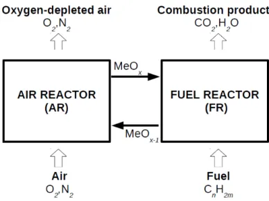
In general, as it is shown in fig. (2.2), the CLC process is mainly composed of a fuel reactor and an air reactor exchanging solid particles acting as oxygen and heat carriers. In the fuel reactor, a reduction reaction is carried out between the solid oxygen carrier and the fuel, for which compositions can be expressed as MeOx and CnH2m, respectively. The reduction reaction produces mainly CO2 and H2O in
the flue gas and converts the oxygen carrier to its reduced form MeOx−1 (reaction (2.1)). After condensation of the water vapour, CO2 is cooled and pressurized in
stages to yield liquid CO2 ready for storage. The reduced material (MeOx−1) is sent back to the air reactor and regenerated by air according to an oxidation reaction (reaction (2.2)).
8 Chapter 2. Generalities on Chemical looping combustion
Fuel Process Main features
Gas CLC Combustion of gaseous fuels with oxygen carriers Solid Syngas-CLC Previous gasification of solid fuels integrated
to CLC Oxygen request for gasification
Solid iG-CLC Gasification of solid fuels inside a CLC fuel-reactor Low cost oxygen carriers are desirable
Solid CLOU Use of oxygen carriers with gaseous O2 release
properties for the combustion of the solid fuel
Tab. 2.2: Summary of the chemical looping processes dedicated for combustion
Fig. 2.2: Schematic description of a CLC process.
The redox cycle may be summarized as follows:
(2n + m)MeOx (s) + CnH2m→ (2n + m)MeOx−1 (s) + nCO2+ mH2O (2.1)
(2n + m)MeOx−1 (s) + (n + m/2)O2 → (2n + m)MeOx (s), (2.2)
where n and m are appropriate stoichiometric coefficients, s indicates a solid species and Me states for metal oxide. While the oxidation reaction (reaction (2.2)) is always an exothermic process associated with a strong heat release, the reduction reaction may be an endothermic or a slightly exothermic reaction, depending on the oxygen carrier and the fuel employed in the CLC system. When the reduction reaction is endothermic, the heat demanded is carried by the oxygen carrier, by which almost the same temperature in the two reactors can be achieved. The overall chemical reaction and the corresponding heat release, over the two reactors in the CLC system, is the same as in conventional combustion where the fuel is
2.3. Chemical looping combustion technologies 9
directly burned by air,
CnH2m+ (n + m/2)O2→ nCO2+ mH2O, (2.3)
with the advantage that combustion takes place without emission of CO2 in the
atmosphere. Due to the unmixed combustion, CLC is an inherent CO2 separation
and it therefore exhibits interesting characteristics that can be summarized here: • Possibility to achieve 100% CO2 capture efficiency (ready for transport and
storage);
• No energy penalty for CO2 separation;
• Low cost CO2 capture technology;
• No nitrogen oxide formation;
• And possible application for existing technologies.
2.3.2 Reactor configurations for CLC of gaseous fuels
CLC requires a continuous circulation of solid particles between two reactors, one of them being the fuel reactor and the other the air reactor, along with an effective oxygen transfer between the gas and the particles for the fuel combustion. Hence, selection of a given reactor configuration is a crucial criterion for a successful long-term CLC operation. Different configurations have been proposed and generally are two interconnected moving or fluidized-bed reactors, alternated packed or fluidized bed reactors and rotating reactors [10,88]. Figures (2.3a-c) show schemes of those configurations.
Based on the effectiveness of the gas-solid reactions in fluidized beds, the concept of interconnected fluidized bed (IFB) reactors is believed to be the best option for the industrial development of chemical looping technologies. In such systems, the reduction reaction converts the fuel mainly into CO2 and H2O in the fuel reactor,
whereas the oxidation reaction regenerates the oxygen carrier in the air reactor. In addition, two loop-seal devices must be added to the IFB system in order to avoid gas leakage between the reactors. The gas-solid reaction rates represent certainly the most fundamental factor for the CLC reactor design. When the reactions are slow, long residence times of the gas and the particles are necessary to transfer the required oxygen to the carrier and to fully convert the fuel. Therefore, tall reactors running with a low superficial gas velocity are required. This is not suitable for a CLC reactor with a high fuel capacity. By contrast, when the reaction rates are fast enough, the superficial gas velocity can be high and this gives the driving force for the solid circulation. Thus, depending on the application, on the fuel and on the oxygen carrier, several systems based on the IFB reactors have been proposed worldwide. Detailed reviews on the development work of appropriated design for CLC applications can be found in [10,18,88] and [117].
An atmospheric circulating system composed of a low-velocity bubbling fluidized bed as fuel reactor and a high-velocity riser as air reactor, has been proposed by
10 Chapter 2. Generalities on Chemical looping combustion
(a) Interconnected fluidized bed reactors (b) Alternating fixed bed reactors
(c) Rotating reactor
Fig. 2.3: Possible reactor configurations for CLC processes [10,88].
Lyngfelt et al. [75]. This configuration is preferred because of the fact that most of oxygen carriers require higher particle residence time for the reduction than for the oxidation. In addition, due to the high volumetric gas flow in the air reactor, which is approximately 10 times larger than that of the gaseous fuel in the fuel reactor, a high velocity is needed in the air reactor in order to keep a reasonable size of the reactors. At the same time, this velocity provides the driving force for the circulation of the particles between the two reactors.
In order to improve the gas-solid contact, a system based on a dual circulating fluidized bed (DCFB) reactors has been proposed by Kolbitsch et al. [60]. A
2.3. Chemical looping combustion technologies 11
scheme of such a system is shown in fig. (2.4). The fuel reactor is operated in the turbulent regime in order to avoid bypassing of unconverted fuel through the fluidized bed and thus improving the gas-solid contact. The air reactor is a fast bed and is responsible for the global solid circulation in the system. In order to prevent gas leakage between the reactors and control the solid circulation rate, the system is equipped with two steam-fluidized loop seals (upper and lower loop seals). An internal solid circulation may occur in the fuel reactor thanks to an internal steam-fluidized loop seal. Finally, a cyclone added at the top of each reactor separates the oxygen carrier particles from the exhaust gases. Compared with other CLC configurations, this system allows lower solid inventories, which is especially relevant at high plant capacities.
Fig. 2.4: CLC process with IFB reactors:
High-velocity riser (air reactor) and fast fluidized bed (fuel reactor) [60].
2.3.3 Oxygen carrier fundamentals
The CLC process strongly depends on the oxygen carrier properties. These prop-erties largely determine the cost of the material (particles’ lifetime, raw material cost, production cost) and its HSE risks. The selection of the appropriate oxygen carrier is considered as one of the most important criterion for a good performance of the CLC process. An ideal oxygen carrier for CLC applications would have the following characteristics:
• Favourable thermodynamical properties, i.e. ability to convert fully the fuel to CO2 and H2O;
12 Chapter 2. Generalities on Chemical looping combustion
• High reactivity for both reduction and oxidation steps, to reduce the solids inventory in the reactors;
• Stability under repeated oxidation/reduction cycles; • High oxygen transport capacity;
• Low tendency for carbon deposition that would release CO2 in the air reactor
reducing CO2 capture efficiency;
• Resistance to attrition and fragmentation; • Environmental friendly characteristics; • And a limited cost.
A lot of experiments have been performed on gaseous, solid and liquid fuels to develop suitable oxygen carriers for different CLC processes. The most studied ones are synthetic materials. They are composed of active metal oxides based on Ni, Cu, Mn, Fe or Co, often supported on porous inerts such as Al2O3, MgAl2O4,
SiO2, ZrO2 and TiO2, in order to increase the reactivity and the durability of the
oxides and also to enhance the ionic conductivity of the solids.
Because of their lower cost with respect to the synthetic materials, the use of some natural minerals for CLC purposes has also been addressed in the literature. The most studied materials of this category are iron ore, ilmenite, manganese ore, and waste materials coming from steel industry and alumina production (bauxite waste, combustion ash, etc.). Compared to the synthetic materials, the major drawback of the natural materials is their low reactivity. Research on improving natural mineral reactivity with the addition of metal oxides or alkali and alkaline (K+, Na+ or Ca++) compounds have been reported.
Today, nearly a thousand of oxygen carriers, including metal oxides, minerals and waste materials, are developed and tested for CLC. Table (2.3) shows a summary of those oxygen carriers tested in continuous CLC units including the operation time of each material. Table (2.4) provides a summary of the operation time for each particular type of oxygen carrier [88]. The total time of operational experience is about 4000 hours [72] and the major contributors are Chalmers University of Technology (CHALMERS), Vienna University of Technology (TWIEN), Institute of Carboquímica belonging to Spanish National Research Council (ICB-CSIC), Tokyo Institute of Technology (TITECH) and Korea Institute of Energy Research (KIER) [10,72].
2.3.3.1 Metal oxide oxygen carriers
To be considered as a potential oxygen carrier for CLC applications, a solid com-pound must have the affinity for reaction with both the fuel gas and the air. Gener-ally, reaction rates with pure metal oxides are quickly decreased after few cycles of reduction and oxidation [10,50,51,88]. Therefore, depending on the application, many different metal oxides mixed with supports or combination of metal oxides with different properties are proposed in the literature. It should then be pointed
2.3. Chemical looping combustion technologies 13
Oxygen carrier Support Application Operation
time (h)
NiO 40% by weight NiAl2O4 10 kW CLC 100
NiO 40% by weight NiAl2O4 10 kWth > 1000 Ni, Fe and Mn-based 300 Wth CLC
NiO 60% by weight Bentonite 50 kWth CLC 28
CuO γ-Al2O3 10 kWth CLC 120
NiO 10 kWth CLC > 50
Ni-based MgO or MgAl2O4 120 kWth CLC
Ni-based 10 kWth CLC 160
Ni-based α-Al2O3 500 Wth CLC 100
Low Ni content CaO/Al2O3 500 Wth CLC 90
NiO 300 W CLC 54
CuO 15% by weight γ-Al2O3 10 kWth CLC 120
Cu-based 1.5 kWth CLOU Cu-based 300 W CLC 45 Fe2O3 Al2O3 300 Wth CLC 40 Fe2O3 Al2O3 500 Wth CLC 50 α-Fe2O3 1 kWth CLC 20 Fe2O3 γ-Al2O3 500 Wth CLC 75 Fe2O3 10 kWth CLC 78
Fe-ESF from bauxite 500 Wth CLC 40
Tierga iron ore 500 Wth CLC 50
Mn-based ZrO2/MgO 300 Wth CLC
Mn3O4 300 Wth CLC 17 CO-based CoAl2O4 50 kWth CLC 25 Fe2O3+NiO Bentonite 1 kWth CLC Ilmenite 100 kWth CLC 12 Ilmenite 300 W CLC 80 NiO+CuO Al2O3 500 Wth CLC 67
Tab. 2.3: Oxygen carriers tested in continuously-operated CLC units [88]
Oxygen carrier type Operation time (h)
Nickel based 2468 Copper based 556 Iron based 390 Manganese based 87 Cobalt based 25 Mixed oxides 149
Ilmenite and other low cost materials 291
Total 3966
14 Chapter 2. Generalities on Chemical looping combustion
out that the possibilities for varying the properties of the material are extremely wide, giving rise to a large number of potential oxygen carriers. This is due to the fact that:
• There are many metal oxides and a large number of possible mixed metal oxides;
• There is a very large number of potential supporting materials and the pro-portions of the active material and the support may be varied as well; • There are several preparation methods which strongly affect the properties
of the oxygen carriers, such as the reactivity and stability during consecutive redox cycles;
• And there are different properties of the oxygen carrier precursors depending on their sources (suppliers).
Abilities to react with the fuel gas and to fully convert it to CO2 and H2O are
im-portant characteristics desired for an oxygen carrier. In order to investigate these properties, thermodynamic analysis of some common metal oxides has been per-formed by Mattisson and Lyngfelt [83]. Fig. (2.5) reports the equilibrium constant log K as function of 1/T for the reduction reaction of different metal oxide/reduced metal species using methane as fuel gas. Since a high log K value means a high affin-ity for methane, it is evident from the figure that, among the candidate metal oxide systems considered, MnO2/Mn2O3, Mn2O3/Mn3O4, CuO/Cu2O and Co3O4/CoO
systems have very high affinity for methane. However, MnO2, Mn2O3, Co3O4 and
CuO decompose at temperatures above 460◦C, 820◦C, 890◦C and 1030◦C, respec-tively. Therefore, except for CuO, these oxides may be unsuitable for the use in high temperature CLC processes [47,83].
A complete fuel combustion to CO2 and H2O is particularly advantageous since
it reduces the amount of the unburned compounds (e.g. CO, H2 or CH4) that
must be recirculated back to the fuel reactor and, more important, reduces the combustion efficiency [10, 83]. In their thermal analysis, Mattisson and Lyngfelt [83] determined the degree of methane conversion to carbon dioxide for the different oxide systems. Their results are reported in fig. (2.6), showing that complete conversion can be reached for Cu2O/Cu, Mn3O4/MnO and Fe2O3/Fe3O4 systems
and almost complete (97%) for NiO/Ni system. Such systems have then been considered as feasible for use as oxygen carriers in a CLC process. However, because of the low melting point of Cu (1085◦C), a CLC process using Cu2O/Cu as oxygen
carrier may need to be conducted at temperatures below 900◦C. Finally, despite of its low yield of CO2, CoO/Co system have also been selected.
In 2006, Jerndal et al. [55] performed a thermal analysis of 27 possible oxygen carriers based on metal oxides of the metals Ni, Cu, Fe, Cd, Mn, Co, Zn, Ce, W, Mo and Ag, except two systems which are based on the transition between metal sulphate to metal sulphide, i.e. Ba and Sr. Three fuels were used in their investigation, CH4, CO and H2. A first analysis based on the gas yields showed
2.3. Chemical looping combustion technologies 15
Fig. 2.5: log K as a function of 1/T in the temperature range 600◦C – 1200◦C for different metal oxide systems [83].
Fig. 2.6: Conversion of CH4 to CO2 as a function of temperature for different
metal oxide systems [83].
among all the systems studied, Cd, Zn, Ce and MoO3 have too low melting points,
16 Chapter 2. Generalities on Chemical looping combustion
1200◦C). For further investigation, the authors excluded all oxide systems with poor conversion (< 92%) and the retained systems have been investigated with respect to temperature drop and possible carbon, sulphide and sulphate formation in the fuel reactor.
The heat release over the fuel and the air reactors in the CLC process is the same as that from normal combustion where the fuel gas is directly burned with oxygen of the air. However, heat involved in each reactor will be function on both the fuel gas and the oxygen carrier used in the process. While the oxidation reaction is always exothermic, the reduction reaction can be exothermic or endothermic depending on the redox system and the fuel gas. Then, if the oxidation reaction is more exothermic than the conventional combustion, the reduction reaction will be endothermic. According to Jerndal et al. [55], the oxide systems feasible for the CLC process are summed up in table (2.5).
Metal Metal or reduced metal oxide (∆Ho/∆Hc)
oxide systems oxydation reaction at 1000 ◦C ratio
NiO/Ni O2 + 2Ni → 2NiO 1.17
CuO/Cu O2 + 2Cu → 2CuO 0.74
Cu2O/Cu O2 + 4Cu → 2Cu2O 0.83
Fe2O3/Fe3O4 O2 + 4Fe3O4→ 6Fe2O3 1.19
Mn2O3/MnO O2 + 4MnO → 2Mn2O3 0.89
Mn3O4/MnO O2 + 6MnO → 2Mn3O4 1.12
Co3O4/Co O2 + 1.5Co → 0.5Co3O4 1.11
CoO/Co O2 + 2Co → 2CoO 1.16
WO3/WO2.722 O2 + 0.278/2WO2.722→ 0.278/2WO3 1.04
BaSO4/BaS O2 + 0.5BaS → 0.5BaSO4 1.20
SrSO4/SrS O2 + 0.5SrS → 0.5SrSO4 1.18
Tab. 2.5: Ratio of the oxidation reaction enthalpies (∆Ho) at 1000◦C of various metals or reduced metal oxides to that of the conventional methane combustion with O2 (∆Hc). Note that ∆Hc = −401.7kJ mol−1 of O2 [55].
For each system, the ratio of the oxidation reaction enthalpy (∆Ho) at 1000◦C of the reduced species to that of the direct methane combustion with O2 (∆Hc) is also shown. A value above 1 for this ratio means that the reduction reaction in the fuel reactor is endothermic, otherwise it is exothermic. Results show that some of the selected redox systems exhibit endothermic reactions with methane. In that case, the fuel reactor will be heated by the circulating particles coming from the air reactor. However, high temperature drops in the fuel reactor should be avoided, otherwise the reduction reaction will slow down or even stop. Table (2.6) reports values of the oxygen ratio, R0, of the selected oxide systems. This
parameter expresses the maximum transported mass of oxygen for a given mass flow of metal oxide and it is quite practical in CLC applications.
In accordance with the above thermodynamic considerations, the systems listed in table (2.6) are highly promising and can be used as oxygen carriers in CLC processes. However, some limitations must be taken into account: i) Cu-based
ma-2.3. Chemical looping combustion technologies 17
Metal oxide systems R0a
NiO/Ni 0.214 CuO/Cu 0.201 Cu2O/Cu 0.112 Fe2O3/Fe3O4 0.033 Mn2O3/MnO 0.101 Mn3O4/MnO 0.070 Co3O4/Co 0.266 CoO/Co 0.214 WO3/WO2.722 0.019 BaSO4/BaS 0.274 SrSO4/SrS 0.348 aR0 = (m ox− mred)/mox
Tab.2.6: Oxygen ratio of suitable metal oxide systems for CLC [55]. moxand mred are the mass of oxidized and reduced material, respectively.
terials, with the melting point of 1085◦C, can not be used above 900◦C, ii) iron, manganese and tungsten oxides have very low oxygen ratios, iii) Ni-based materials leave some unconverted fuel in the form of CO and H2at the fuel reactor outlet and
iv) for the systems BaSO4/BaS and SrSO4/SrS, SO2 may form by decomposition
of the sulphate mainly at high temperatures and low total pressures. To increase the reactivity, durability and fluidizability, the aforementioned oxygen carriers are used together with inert supports. It should be noted that, in this case, the oxygen ratio will strongly depend on the metal loading [47] and will often decrease [55]. Oxygen ratios of different supported oxygen carriers are summarized in table (2.7). Apart from thermodynamics and some physical properties (e.g. density, active sur-face area, particle size and crushing strength), economic cost and health, safety and environmental (HSE) issues are other important features for a successful oxygen car-rier. In general, cobalt and nickel are the most expensive metals followed by copper and the cheapest ones are manganese and iron. Regarding HSE aspects, nickel and cobalt are considered as materials exhibiting the highest risk during operation due to which safety measures are required for their usage. On the contrary, iron and manganese are non-toxic in nature. Finally, the use of copper as oxygen carrier is believed to have less environmental problems than nickel and cobalt [10,47,74,88].
18 Chapter 2. Generalities on Chemical looping combustion
Metal oxide systems Metal loading (%) R0
NiO/SiO2 35 0.074 NiO/Al2O3 20–60 0.043–0.16 NiO/NiAl2O4 40–60 0.09–0.13 NiO/MgAl2O4 37–60 0.09–0.13 NiO/TiO2 40–60 0.09–0.13 CuO/SiO2 41 0.083 CuO/Al2O3 14–35 0.027–0.08 CuO/MgAl2O4 43 0.087 Fe2O3/SiO2 39 0.012 Fe2O3/Al2O3 60 0.027 Fe2O3/MgAl2O4 32 0.0096 Mn2O3/SiO2 47 0.048 Mn2O3/MgAl2O4 46 0.047 Mn2O3/Al2O3 28–60 0.02–0.07 Mn2O3/MgZrO2 40 0.028 CoO/Al2O3 28–35 0.07
Tab. 2.7: Oxygen ratio of various oxygen carriers [47]
2.3.3.2 Mixed oxide oxygen carriers
As discussed above, a lot of metal oxides mixed with different support materials revealed very interesting characteristics for their CLC usage. However, benefits and limitations are associated to each type of oxygen carrier and no single material will provide all of the characteristics of an ideal oxygen carrier for CLC processes. Hence, different complex metal oxides and perovskite-based oxygen carriers are prepared and tested for CLC applications. The main objectives of such an approach may be: • To improve reactivity and stability of the particles over repeated redox cycles; • To increase the fuel conversion ratio;
• To improve the mechanical strength and reduce attrition of the particles; • To minimize the carbon deposition;
• To minimize the use of toxic metals, such as nickel oxide; • To decrease cost of the oxygen carrier materials.
Jin et al. [56] examined the gas-solid reaction kinetics in a natural-gas-fueled CLC operated in a fixed bed reactor. NiO/NiAl2O4 and CoO-NiO supported on YSZ
(Yttria-Stabilized Zirconia) have been used as oxygen carriers. Equal amounts of NiO and CoO were used in the case of the double metal oxide (CoO-NiO). The authors found that the double metal oxide provided a complete avoidance of car-bon deposition and outstanding regeneration properties over repeated redox cycles, but reaction rates were slightly lower than those of the individual metal oxide
2.3. Chemical looping combustion technologies 19
(NiO/NiAl2O4). In addition, due to their low thermal stability and their high
cost, YSZ supported CoO-NiO oxygen carriers became less interesting [88, 47]. Mohammad et al. [47] demonstrated the excellent reactivity and stability of NiO-CoO/Al2O3 carrier after addition of Co by varying nickel loading from 2.5 to 20
wt%. Adánez et al. [11] reported that the presence of NiO stabilized the CuO phase in their prepared bimetallic Cu-Ni/Al2O3 oxygen carrier, providing a high
durability along with a high reaction temperature.
The addition of NiO to iron-based oxygen carrier particles has also been investi-gated. Son and Kim [106] carried out CLC experiments in an annular shape CFB reactor using different combinations of NiO and Fe2O3 supported on bentonite.
They detected no presence of CO and H2 at the fuel reactor outlet and only small
amounts of NOx were detected at the air reactor outlet. They also found that the reactivity of the particles increases with increasing NiO content, up to a maximum corresponding to an optimum ratio of 75:25 for NiO/Fe2O3. Lagerbom et al. [66]
observed that alloying of Fe2O3/Al2O3 with small amounts of NiO improved the
reactivity but decreased the mechanical strength.
Rydén et al. [101] evaluated the performances of different oxygen carriers for their use in chemical looping combustion (CLC) and chemical looping reforming (CLR) applications. Three bimetallic oxide materials were studied: NiO-MgAl2O4, Fe2O3
-MgAl2O4 and Mn3O4-MgZrO2, containing respectively 60%wt. of NiO, 40%wt. of
Fe2O3and 40%wt. of Mn3O4. Mixtures prepared simply by mixing particles of those
materials were also analyzed. The authors found that carbon formation occurred during NiO-MgAl2O4 oxygen carrier tests, which was attributed to the catalytic
properties of nickel. Fe2O3-MgAl2O4 and Mn3O4-MgZrO2, with or without added
NiO-MgAl2O4particles, were found to have properties that could be useful for CLC.
They also concluded that Fe2O3-MgAl2O4 could be used for CLR purposes.
Materials containing Cu and Fe have been prepared by different researchers. Rif-flart et al. [98] used complex compounds containing Cu and Fe and reported a high oxidation rate with Cu0.95Fe1.05AlO4 compound, but a lower reduction rate than
that obtained with a reference Ni-based oxygen carrier (NiO60NiAl2O4). Ksepko et
al. [64] investigated the performance of Fe2O3-MnO2 oxygen carriers supported on
zirconia (ZrO2), sepiolite (Mg4Si6O15(OH)2.6(H2O)) and alumina (Al2O3). They
found that all the oxygen carriers exhibited stable performance and the support had an important effect on the reaction rate. Mungse et al. [87] carried out CLC experi-ments using methane as fuel and a mixed oxide of Cu and Mn, CuMn2O4, as oxygen
carrier. They found that the methane combustion efficiency and the oxygen carry-ing capacity were not altered with the increase of the time operation. Moreover, CuMn2O4 showed high tendency towards CO2 formation. However, agglomeration
20 Chapter 2. Generalities on Chemical looping combustion 2.3.3.3 Perovskites as oxygen carriers
In addition to bimetallic oxides, more complex metal oxides with perovskite struc-ture have been proposed to be used as oxygen carriers. Although perovskite is a calcium titanium oxide mineral composed of calcium titanate (CaTiO3), it lends its
name to materials with the same type of crystal structure as CaTiO3. In this
re-search area, Rydén et al. [101] found that La0.5Sr0.5Fe0.5Co0.5O3−δ which has a very
high thermal stability and decent mechanical properties, provided high selectivity towards CO2 and H2O and thus should be feasible for CLC applications. They
also reported that perovskite structures like LaxSr1−xFeO3−δ can be interesting for
CLR applications due to their excellent selectivity towards H2 and CO.
Perovskites of CaMnO3−δfamily, where δ expresses the amount of oxygen deficiency,
attracted great interest as oxygen carriers mainly due to their oxygen uncoupling property. This characteristic is particularly interesting in solid-fueled CLC pro-cesses, such as Chemical Looping with Oxygen Uncoupling (CLOU) and in-situ Gasification CLC (iG-CLC) processes. Indeed, such materials have the ability to release gaseous oxygen in the fuel reactor, which increases the fuel conversion. As function of the oxygen partial pressure and the surrounding temperature, the oxygen deficiency makes perovskites interesting for chemical looping applications. Indeed, in an oxygen-poor environment (fuel reactor), δ would increase, thus releasing oxy-gen, whereas it would decrease in an oxygen-rich environment (air reactor). Bakken et al. [15] reported a study on the redox energetics of the perovskite CaMnO3−δ and showed that, although this material releases gas-phase oxygen
at conditions relevant for CLC, it unfortunately decomposes to Ca2MnO4−δ and
CaMn2O4, leading to deactivation of the oxygen carrier. To prevent the
decom-position to some extent, Rydén et al. [100] incorporated titanium in the crystal structure of the perovskite and the produced material (CaMn0.875Ti0.125O3−δ) was
tested in a circulating fluidized bed reactor. The particles exhibited oxygen release as well as good methane conversion. However, chemical changes in the perovskite structure occurred during the experiments and resulted in some loss of the parti-cles’ reactivity with methane. Källén et al. [57] examined Mg-doped CaMnO3−δ as
oxygen carrier in a 10kWthnatural gas-fired CLC unit. The synthesized oxygen car-rier (CaMn0.9Mg0.1O3−δ) released oxygen above 700◦C in an inert atmosphere. In
addition, nearly complete fuel combustion was obtained at 900◦C, suggesting that
a substantial part of the fuel was converted by gaseous oxygen released from the particles. Later, the same material was used by de Diego et al. [26] in thermogravi-metric analysis (TGA) experiments. Oxygen carrier reactivities with CH4, H2 and
CO, were found to increase with the number of redox cycles, whereas the oxygen release property was strongly reduced. Another study using Mg and Ti doped into CaMnO3−δ perovskite structure was performed by Hallberg et al. [44] in a 300W
natural gas-fired CLC unit. The examined materials, based on a perovskite type structure with the formula CaMn1−xMxO3−δ (M = Mg or Mg and Ti), showed a
high CO2 yield at 900◦C, an oxygen release ability at elevated temperature (700
decompo-2.4. Reaction schemes and kinetics in CLC systems 21
sition to CaMn2O4 was detected for CaMn0.9Mg0.1O3−δ and a few amount of fine
particles (< 45µm) were collected in the filters for all the tested materials. The perovskite material CaMn0.775Mg0.1Ti0.125O3−δ was again studied by Abad et al.
[8] using TGA experiments to establish its redox kinetics and results were compared to that reported previously by de Diego et al. [26]. It was found that doping the parent material (CaMnO3−δ), not only with Mg, but also with Ti, stabilized the
perovskite structure. The oxygen release property, which was mostly lost for the mono-doped material, was maintained for the codoped material and the oxygen transport capacity was higher.
According to the above discussion, perovskite type materials based on the abun-dantly available manganese ores and calcium precursors appear to be among the best alternatives to costly and harmful metal oxides, such as Ni-based metal ox-ides, for a use in chemical looping applications. Their abilities to reach complete gas conversion and release gaseous oxygen at conditions relevant for chemical loop-ing processes while showloop-ing little attrition, make them very attractive. However, a challenge to CaMn1−xMgyTix−yO3−δ oxygen carriers is their lack of long term
stability and eventual deactivation under sulfurous environments.
2.4
Reaction schemes and kinetics in CLC systems
The reaction mechanism and its kinetic parameters are crucial for developing a mathematical model suitable for the design, the simulation and the optimization of a CLC system. In general, gas-solid reactions are widely investigated in many chemical processes and many reaction models have been proposed. The reaction mechanisms and the kinetic models related to gas-solid reactions that are applied for CLC of methane are reported in this section.
2.4.1 Reaction schemes
The major reactions considered for CLC modeling purposes are given below. The oxidation of the oxygen carrier (designated hereafter as M and MO in the reduced and oxidized states, respectively) can be simply described by the reaction (2.4) and its reduction by methane by the reaction (2.5), giving H2O and CO2 as primary
products. Other products, such as H2 and CO, could be involved during the
re-duction process, making the one-step mechanism (2.5) unsuitable for the reaction modeling. In this case, the general scheme represented by the reactions (2.6), (2.7) and (2.8) can be assumed. In addition to those reactions, methane could be re-formed by steam, according to the reactions (2.9) and (2.10), and the resulting products, H2 and CO, promote the reactions (2.7) and (2.8). Carbon formation
may compromise the conversion of methane to H2O and CO2, either by methane
decomposition, according to the reaction (2.11) or by the reverse Boudouard re-action (2.12). At the same time, carbon can react with steam according to the reaction (2.13). Finally, the shift reaction (2.14) is usually considered when CO2,
22 Chapter 2. Generalities on Chemical looping combustion M + 0.5O2 → MO (2.4) MO + 0.25CH4 → M + 0.25CO2+ 0.5H2O (2.5) MO + CH4 → M + CO + 2H2 (2.6) MO + CO → M + CO2 (2.7) MO + H2→ M + H2O (2.8) CH4+ H2O ⇋ CO + 3H2 (2.9) CH4+ 2H2O ⇋ CO2+ 4H2 (2.10) CH4⇋C + 2H2 (2.11) CO ⇋ 0.5C + 0.5CO2 (2.12) C + H2O ⇋ CO + H2 (2.13) CO + H2O ⇋ CO2+ H2 (2.14)
Generally, methane conversion is well described by the direct reaction (2.5) if Mn-or Fe- based oxygen carriers are used in the process [9,20], whereas it is assumed to evolve according to the reactions (2.6), (2.7) and (2.8) for Cu-based oxygen carriers [4, 7]. Steam reforming of methane, showed in the reactions (2.9) and (2.10), has been found relevant in the fuel reactor when Ni-based oxygen carriers are used [6,11,22,34,56]. In this case, H2 and CO are likely to be formed when the
temperature is low or the oxygen in the particles is depleted. However, an increased total pressure promotes the reverse reaction (2.9), thus decreasing the conversion of methane by steam reforming. Concerning the modeling procedure, the kinetics of those reactions may be needed. The reaction (2.11), which is favoured at high temperature and the reaction (2.12), which is favoured at low temperature, are kinetically slow, but metals such as Ni and Fe could catalyze them [11, 22, 34]. In practice, carbon can be removed from the oxygen carrier surface by gasification with H2O (reaction (2.13)), or with CO2 (reverse of the reaction (2.12)). However,
since carbon formation has not been observed during continuous CLC operation, it could be omitted in the reaction scheme [10]. Finally, the shift reaction (2.14) offsets the disappearance of the highest reactive gas (H2 or CO) with the oxygen
carrier. This fact is involved in CLC systems using Ni- or Cu-based oxygen carriers [6, 4, 7, 11]. Therefore, adding the shift reaction kinetic in the modeling of the overall reduction process could be necessary.
In addition to the reaction (2.5), other reactions can be involved in the fuel reac-tor when perovskites are used as oxygen carriers. As previously discussed, these materials may release gaseous oxygen at conditions relevant for CLC processes and therefore gaseous combustion of methane by the released oxygen can also take place in the fuel reactor. The amount of oxygen available for the gaseous combustion is related to the oxygen deficiency δ of the perovskite material, meaning to the dif-ference between δAR in the air reactor and δF R in the fuel reactor. Therefore, for a CLC modeling purpose, it could be necessary to account for the kinetic of the uncoupling process [8, 26], showed below by the reaction (2.15) and, at least, for that of the overall reaction (2.16) of the methane combustion by the gas-phase O2.
![Fig. 2.1: Plant configurations for the three main CO 2 capture processes [114].](https://thumb-eu.123doks.com/thumbv2/123doknet/3074524.86854/17.892.247.669.168.486/fig-plant-configurations-main-capture-processes.webp)

![Fig. 2.6: Conversion of CH 4 to CO 2 as a function of temperature for different metal oxide systems [83].](https://thumb-eu.123doks.com/thumbv2/123doknet/3074524.86854/27.892.273.629.602.970/fig-conversion-function-temperature-different-metal-oxide-systems.webp)
![Tab. 2.8: Expressions for the SCM in the particle and the Grain model [10]](https://thumb-eu.123doks.com/thumbv2/123doknet/3074524.86854/39.892.170.749.464.895/tab-expressions-scm-particle-grain-model.webp)
![Fig. 3.1: Gas pressure drop vs. gas velocity in fluidized beds [86].](https://thumb-eu.123doks.com/thumbv2/123doknet/3074524.86854/42.892.190.683.598.945/fig-gas-pressure-drop-gas-velocity-fluidized-beds.webp)
![Tab. 4.1: Operating conditions of the air-natural gas combustion from experiments [30]](https://thumb-eu.123doks.com/thumbv2/123doknet/3074524.86854/65.892.166.748.810.1044/tab-operating-conditions-air-natural-gas-combustion-experiments.webp)