HAL Id: hal-01943918
https://hal-mines-albi.archives-ouvertes.fr/hal-01943918
Submitted on 4 Dec 2018
HAL is a multi-disciplinary open access
archive for the deposit and dissemination of
sci-entific research documents, whether they are
pub-lished or not. The documents may come from
teaching and research institutions in France or
abroad, or from public or private research centers.
L’archive ouverte pluridisciplinaire HAL, est
destinée au dépôt et à la diffusion de documents
scientifiques de niveau recherche, publiés ou non,
émanant des établissements d’enseignement et de
recherche français ou étrangers, des laboratoires
publics ou privés.
Short crack propagation from cracked non-metallic
inclusions in a Ni-based polycrystalline superalloy
Damien Texier, Jean-Charles Stinville, Mclean Echlin, Stéphane Pierret,
Patrick Villechaise, Tresa Pollock, Jonathan Cormier
To cite this version:
Damien Texier, Jean-Charles Stinville, Mclean Echlin, Stéphane Pierret, Patrick Villechaise, et al..
Short crack propagation from cracked non-metallic inclusions in a Ni-based polycrystalline superalloy.
Acta Materialia, Elsevier, 2019, 165, pp.241-258. �10.1016/j.actamat.2018.11.051�. �hal-01943918�
Short crack propagation from cracked non-metallic inclusions in a
Ni-based polycrystalline superalloy
Damien Texier
a,b,c,*, Jean-Charles Stinville
b, McLean P. Echlin
b, St!ephane Pierret
d,
Patrick Villechaise
a, Tresa M. Pollock
b, Jonathan Cormier
a,**aInstitut Pprime, UPR CNRS 3346, ISAE-ENSMA, T!el!eport 2, 1 avenue Cl!ement Ader, BP 40109, Futuroscope-Chasseneuil Cedex, 86961, France bMaterials Department, University of California Santa Barbara, Santa Barbara, CA, 93106, United States
cInstitut Cl!ement Ader (ICA), Universit!e de Toulouse, CNRS, IMT Mines Albi, INSA, ISAE-SUPAERO, UPS, Campus Jarlard, F-81013, Albi, France dSAFRAN Aircraft Engines, Site de Villaroche, Rond-Point Ren!e Ravaud, Moissy-Cramayel, 77550, France
Keywords: Low cycle fatigue Superalloy 718DA Short crack propagation Non-metallic inclusions
Focus-ion-beam cross-section (FIB-cross section)
a b s t r a c t
Fatigue cracks initiating from surface and sub-surface non-metallic inclusions (NMIs) have recently been demonstrated to be a necessary but not sufficient explanation for atypically short low-cycle fatigue life in Inconel 718 alloy at intermediate temperature. Therefore, the early stages of short crack propagation from surface NMIs were investigated in a crystallographic and two-dimensional versus three-dimensional morphological manner after room temperature low cycle fatigue (LCF) testing. In the pre-sent investigation, NMIs were purposely pre-cracked using different techniques to suppress the natural crack initiation period and thus the incubation period prior to the early stages of crack propagation. Under such fatigue testing conditions, different mechanisms of crack transmission from pre-cracked NMIs were identified: (i) no propagation, (ii) NMI/adjacent metallic grain interfacial debonding, (iii) transgranular crack propagation within the adjacent metallic grain. Focused-ion-beam cross-section observations of numerous fatigue tested NMIs aimed to define a morphological criterion for non-propagating NMIs. Large cracked NMIs at the surface (2c) with limited extension into the depth (a) did not propagate under such fatigue conditions for 2c/a ratio higher than 3. Furthermore, specific crystallographic relationships between NMIs and the adjacent metallic grain explained different crack propagation configurations from pre-cracked NMIs, i.e. interfacial debonding and transgranular crack propagation involving single or multiple-slip activity.
1. Introduction
Inconel 718 (IN718) alloy is a wrought nickel-base superalloy commonly used for structural components operating at tempera-tures up to 650!C [1]. IN718 alloy exhibits high strength and
suit-able low cycle fatigue (LCF) resistance, critical for rotating massive components for aeronautic applications, such as turbine disks [2,3]. For such critical applications, fine grain microstructures in the range of 5e15
m
m (ASTM 12 to 9) are expected to maximize fatigueperformance. To assess such performance in this range of grain sizes, “direct aged” forging/post heat treatment route of wrought IN718 alloys has been adopted [4,5]. Standard precipitation treat-ments were directly applied after the last forging stages at tem-peratures close to the
d
-phase solvus, without any solution heat treatment. This process route subsequently confers finer grain size and higher amount of the strengtheningg
’’-phase microstructures than standard solution treated variants. This IN718 metallurgical variant is called the direct-aged version of the IN718 alloy (IN718DA).However, grain size refinement and high fraction of strength-ening precipitates might have some design limitations since coarser brittle microstructural features, i.e. carbides (NbC), nitrides (TiN) or carbonitrides (NbCeTiN) referred to here as non-metallic inclusions (NMIs), appear to be crack initiation sensitive features under cyclic stresses [6e14]. Depending on the operating temper-ature, NMIs have been reported to fail (i) by NMI cracking in a
*Corresponding author. Institut Cl!ement Ader (ICA), Universit!e de Toulouse, CNRS, IMT Mines Albi, INSA, ISAE-SUPAERO, UPS, Campus Jarlard, F-81013, Albi, France.
**Corresponding author. Institut Pprime, UPR CNRS 3346, ISAE-ENSMA, T!el!eport 2, 1 avenue Cl!ement Ader, BP 40109, Futuroscope-Chasseneuil Cedex, 86961, France. E-mail addresses:damien.texier@mines-albi.fr(D. Texier),jonathan.cormier@ ensma.fr(J. Cormier).
brittle manner due to the application of the external loading as low as 60% of the 0.2 pct.-offset yield strength [6,7,9,10,13,15,16], (ii) by NMI/metallic matrix debonding due to cyclic stresses [7,16], (iii) by through-metallic-matrix-oxide eruption cracking due to selective fast growth oxidization at high temperature [17e20], or by (iv) machining and surface finishing operations [8,21e23]. A recent study reported that the combination of fine grain microstructure (15
m
m mean diameter and finer grain size microstructure, i.e.ASTM 9 and higher values) and a content of
d
-phase lower than 3.0% (inversely a highg
’’-precipitates content) can occasionally lead to a ten-to-hundred-fold reduction in fatigue life at intermediate temperature [6].The current fatigue life prediction approaches for failure of critical components are based on the probability of the worst-case occurrence [24]. Such lifespan variability considerably restricts a design efficient usage of the IN718DA alloy for critical structural components despite its overall improvement of the fatigue per-formance. Therefore, a mechanistic understanding of the origin of these non-systematic low fatigue life failures is required. Specif-ically a criterion for crack propagation from NMIs is needed. NMIs have been shown to be most detrimental in the low temperature range at high stress level, where the brittle behavior of inclusions and strain localization within the surrounding metallic grains is likely maximal [8e11,25,26]. Recent studies also highlight potential danger from (sub)-surface NMIs in the low plastic deformation regime leading to very short fatigue life.
In this present study, early life failures from NMIs in IN718DA alloy at room temperature have been examined. Since the principal crack systematically initiated from surface/sub-surface NMIs for abnormally short fatigue life, this study has focused on develop-ment of morphological and crystallographic criteria via study of multiple cracked NMIs and their neighboring grains. Due to the stochastic incubation time for crack initiation within NMIs, a frac-tion of NMIs were “naturally” cracked prior to fatigue testing. Two different ways to introduce prior damage were investigated. The early stages of short crack propagation from these pre-damaged inclusions was followed at different life fractions at room temper-ature via electron back-scattered diffraction (EBSD) characteriza-tion. Focused-ion-beam cross-section (FIB-CS) characterizations were employed to evaluate three-dimensional shape factors influ-encing the crack growth capability from surface NMIs.
2. Material and experimental conditions 2.1. Materials
Three experimental forged pancakes were produced in the present study in order to obtain three different IN718DA micro-structures from the same initial ingot. The three pancakes subse-quently have a similar non-metallic-inclusion (NMI) microstructure in terms of size, morphology, fraction and distribution from pan-cake to panpan-cake. The initial ingot was a commercially vacuum in-duction melted ingot with the following nominal composition (in weight %) Ni-0.56Al-18.0Cr-17.3Fe-0.14Co-5.4(Nb þ Ta)-0.023C. The height and the diameter of the initial cylindrical ingot were 250 mm and 100 mm, respectively. The goal of the processing/ microstructure design was to produce three slightly different mi-crostructures of IN718DA matching with the metallurgical specifi-cations of abnormally short fatigue life specimens defined in a previous study (Ref. [6]): fine grain microstructure (15
m
m mean diameter and finer grain size microstructure/ASTM 9 to 12) and content ofd
-phase lower than 3.2%. The different experimental pancakes were forged by hot-die forging by SAFRAN Aircraft En-gines, and are denoted PAN-X. Prior to forging, ingots were heated up to 985!C for 3 h, i.e. up to a temperature slightly lower than thed
-phase solvus temperature. The main difference in the forging parameters for the production of the three experimental metal-lurgical states was the upsetting forging rate, as shown inTable 1. Pancakes were water quenched after forging, then directly aged with a standard aging treatment. The standard aging treatment consists in a 8 h dwell at 720!C, followed by a controlled cooling(0.83!C.min#1) down to 620!C. A second 8 h dwell was performed
at this latter temperature, then air cooled to room temperature. 2.2. Micromechanical specimens extraction and preparation
Micromechanical specimens were extracted with electro-discharge machining (EDM) from a homogeneous region of the pancakes in terms of microstructure, identical to the one investi-gated in Ref. [7]. The loading direction of the specimen was parallel to the radial direction of the pancakes. The specimen geometry consists in flat pin-loaded specimen with a gage length of 10 mm, a gage width of 2 mm, a total length of 32 mm, a head width of 10 mm, and a thickness of 1 mm (see e.g. Ref. [6] for the drawing of the micromechanical specimen). Micromechanical specimens were mechanically ground then polished down to a 1
m
m diamond par-ticle finishing (faces and edges with a particular attention in the radius between the gage zone and the head). The gage zone of the specimens was finally electrochemically polished with a 10% vol. perchloric acid diluted in methanol solution under 45 V at 4!C. Thisfinal step aimed to reduce superficial residual stresses from me-chanical polishing and to prepare the specimen surface for further EBSD characterizations.
2.3. Tensile and interrupted fatigue testing at room temperature Tensile tests were performed at room temperature on an Ins-tron™ 1362 electromechanical fatigue machine under displace-ment control with a strain rate of 10#4 s#1. The dimensional
variations of the specimen were continuously recorded with both the displacement of grips and an extensometer sampling the specimen gage length. A summary of the 0.2% offset yield strength of the three pancakes is reported inTable 2.
Low cycle fatigue (LCF) fatigue tests were performed at room temperature under load control, with a positive stress ratio Rs¼ 0.05 using a 1 Hz triangle waveform. The maximum stress was
chosen to be equal to the stress measured at a total deformation of 0.67% for each microstructure (
s
max (25!C)z1270 MPa).Inter-rupted LCF tests were conducted to investigate the early stage of crack propagation. Fatigue tests were interrupted after 10, 100, 1,000 and 5,000 and 10,000 cycles. Fifteen to twenty five cracked NMIs were observed and tracked per specimen. Different cases of NMIs were investigated, i.e. isolated carbides, nitrides or carboni-trides or cluster of those NMIs.
2.4. Damage introduction prior to LCF experiments
In a previous study, crack initiation from surface/sub-surface NMIs was reported to be a necessary condition for abnormally short fatigue life (Ref. [6]). The goal of cracking NMIs prior to LCF testing was to investigate the early stages of natural crack propa-gation from NMIs. Pre-cracking multiple NMIs aimed to investigate multiple initiation site configurations on the same sample, i.e. isolated carbides, nitrides or carbonitrides or clusters of those NMIs. This aspect is of major interest since crack initiation from NMIs did not necessarily lead to abnormally short fatigue life (Ref. [6]). Two methods were developed to crack a fraction of NMIs prior to LCF tests, i.e. interrupted tensile tests in the plastic domain (3plastic¼ 0.75% /
s
maxz1350e1395 MPa) anddomain (3total¼ 0.4% /
s
z820 MPa þ200 mN microhardness load locally), this latter technique aiming to create “natural” cracks without affecting the surrounding matrix. As reported in a pre-liminary study (Ref. [6]), approximately thirty percent of NMIs are cracked after interrupted tensile test at 0.75% plastic strain. For pre-damage introduction via micro-indentation, around 20 to 30 in-clusions were indented and 80% of them cracked. Only coarse NMIs (D > 10m
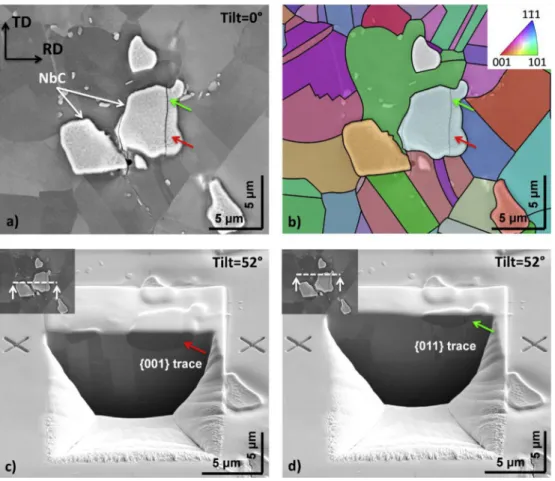
m) were micro-indented for technical reasons and feasi-bilities. Typical examples of pre-cracked NMIs in tension in the plastic domain or via microindentation were detailed in Ref. [7]. Interrupted tensile tests reveal (i) slightly open cracked NMIs without severe plastic deformation in the surrounding metallic matrix, (ii) open cracked NMIs with intense plasticity in the vicinity of the crack tip involving the activity of at least two slip systems, (iii) intense slip activity in the surrounding grains of a cracked NMI. Typical examples of cracked NMIs via micro-indentations under loading within the macroscopic elastic regime were: (i) cracked NMIs whose crack split entirely the inclusion, (ii) partially cracked NMIs, (iii) cracked NMIs due to the tensile loading, i.e. without indent. NMIs failed in a brittle manner for the two ways to pre-damage them. The crack path within NMIs was complex, gener-ally along several different crystallographic planes. Plane trace analyses at the surface of the cracked NMIs via EBSD character-izations identified two different crystallographic planes for the cleavage of NMIs, i.e. {001} and {011} planes with similar proba-bilities of failure from {001} or {011} planes. FIB cross-section ob-servations were also conducted on a pre-cracked carbide in tension depicting a slight deviation of the crack path at the surface (green and red arrows inFig. 1). Cross-sectional observations revealed the combination of two crystallographic cleavage planes, i.e. {011} and {001} crystallographic plane depicted as green and red arrows inFig. 1, respectively. The two planes present a low-angle-surface-trace misorientation but a high-twist-angle-cross-section low-angle-surface-trace misorientation. Therefore, the crack path within a single crystal orientation NMI was relatively complex, especially from micro-indentation induced pre-cracks.
2.5. Microscopy observations and EBSD analyses
A FEI/Philips XL30 and a Jeol 6400 scanning electron microscope were used in secondary electron mode and a back-scattered elec-tron mode in the 15e20 kV range for microstructural, crack prop-agation and fractographic observations. A Zeiss Axio Imager Vario optical microscope was used in a differential interference contrast mode at high magnification for the evaluation of short crack propagation from several pre-cracked NMIs at the different fatigue
interruptions. During the optical observations, the fatigued speci-mens were in-situ loaded with a DEBEN microtensile apparatus up to 425 MPa, i.e. one third of the maximal cyclic stress, in order to slightly open the small cracks and subsequently detect them. An image processing procedure based in image registration then image difference between the N-cycle micrograph and the 0-cycle micrograph aimed to better highlight the crack path using Fiji software [27]. FIB cross-sections were prepared with a FEI Helios FEG system (FIB-SEM). The region of interest (ROI) was first platinum-plated with an electron deposition (50 nm thin Pt-layer) not to alter the surface of the ROI then with an argon deposition (250 nm thick Pt-layer) to limit edge effects during the FIB cross-section procedure. EBSD scans were carried out with an OIM™ software from EDAX acquisition setup equipped on a conventional SEM of JEOL 6100 type. 80 % 150
m
m2 areas around all the NMIsstudied after interrupted LCF tests were analyzed with a 0.2
m
m step hexagonal grid pattern. The EBSD analyses aimed to document both the effect of the orientation of the NMIs but also the neigh-borhood grains related to the macroscopic load application on the ease of short crack propagation. A large area (280 % 350m
m2) was analyzed for each pancake variant in order to characterize the grain microstructure. EBSD scans were conducted according to a regular hexagonal grid pattern with a scan step of 0.25m
m.3. Results
3.1. Microstructure of the different pancakes
The microstructures of the three experimental pancakes were investigated by means of EBSD characterization in the TD-RD plane. Slight differences in terms of grain size were observed for the three pancakes, as depicted inFig. 2via the inverse pole figure (IPF) maps represented according to the radial direction of the pancake, i.e. the loading direction of LCF specimens. All the pancake variants possessed equiaxed microstructures with twinned grains. It is worth noting that higher upsetting forging rates lead to finer grain size microstructures ðDPAN3&4
mean <DPAN1&2mean <DPAN5&6mean Þ and higher
content of
d
-phase (f ðd
phaseÞPAN3&4mean >f ðd
phaseÞPAN1&2mean >f ð
d
phaseÞPAN5&6mean ). A summary of these microstructuralcharacter-istics is reported inTable 2. Since the three experimental pancakes were forged from the same input billet, the morphology and pro-portion of non-metallic inclusions should be constant for the different pancakes. Qualitative observations of hundreds of NMIs per experimental pancakes aimed to support this supposition. EBSD characterizations highlighted that no preferential crystallo-graphic orientations was found for such forging conditions since the maximal texture index for ODF maps represented on IPF maps according to the loading direction is lower 1.7. In other words, the three experimental pancakes gather the microstructural conditions to favor abnormally low LCF life according to our previous study Ref. [6], but with slight microstructural variations. A more detailed characterization of the three experimental pancakes is reported in Ref. [7].
Table 1
Forging parameters for the production of the three experimental microstructures.
PAN-1&2 PAN-3&4 PAN-5&6
Forging temperature (!C) 985 985 985
High temperature dwell duration prior to forging (h) 3 3 3
Upsetting forging rate (mm.s#1) 5 15 3
Cooling route Static water quench Static water quench Agitated water quench
Table 2
Summary of different microstructural parameters and macroscopic mechanical behavior of the three experimental pancakes.
PAN1&2 PAN3&4 PAN5&6 Average grain size (mm) 8.7 7.5 11.6 Maximum grain diameter (mm) 23.5 23.5 28.5
d-phase content (%, image proc.) 1.5 ± 0.2 2.0 ± 0.3 0.8 ± 0.2 Yield Stress @RT (MPa) 1323 ± 6 1332 ± 4 1295 ± 5
Fig. 1. FIB cross-section and EBSD characterization of a pre-cracked carbide (NbC) in tension involving the combination of {001} and {011} cleavage planes. a) Top view observation of the pre-cracked carbide prior to FIB machining. Green and red arrows highlight two different traces of plane along the crack path. b) EBSD map of the region of interest showing the single orientation within the pre-cracked NMIs. The EBSD map is represented as IPF maps according to the loading direction (horizontal). c) FIB-cross section observation of the bottom region of the pre-cracked carbide (red arrow inFig. 1a). The crystallographic plane has been identified as {001} crystallographic plane. d) FIB-cross section observation of the top region of the pre-cracked carbide (green arrow inFig. 1a). The crystallographic plane has been identified as {011} crystallographic plane. (For interpretation of the references to color in this figure legend, the reader is referred to the Web version of this article)
Fig. 2. Grain microstructure of the different microstructures represented as orientation maps according to the RD direction (loading direction): a) 1&2, b) 3&4, c) PAN-5&6.
3.2. Investigation of the short crack propagation at room temperature
3.2.1. Crack propagation from pre-damaged non-metallic inclusions Interrupted fatigue tests were performed at room temperature for the three experimental pancakes in order to investigate the initial crack propagation steps from NMIs. Prior to fatigue testing, SEM surface observations were conducted after pre-damaging conditions in order to identify and further follow pre-cracked NMIs after several cycles. Fifteen to twenty five cracked NMIs were observed per specimens for each fatigue interruption (10, 100, 1,000, 5,000 and 10,000 cycles). Different cases of NMIs were investigated, i.e. isolated carbides, nitrides or carbonitrides or cluster of those NMIs.Fig. 3 illustrates the evolution of a crack propagating from a cluster of nitrides (TiN) at different fatigue life fractions (the loading direction is horizontal), the extent of the crack being highlighted by white arrows. The cluster of nitrides was pre-damaged via interrupted tensile test in the early plastic domain. As shown in the insert inFig. 3a, only the upper nitride was cracked following the pre-damage introduction. No evidence of crack propagation was found after 1,000 cycles for this specific region of interest. At 5,000 cycles, the crack propagation through the second nitride and in the surrounding grains was clearly depicted inFig. 3b. The crack propagation in the upper grains was not straightforward to observe via optical microscopy, but the aforementioned image processing procedure aimed to reveal it; this crack path in the upper grain was then confirmed when observing this region of interest after 10,000 cycles. The total crack length was about 21
m
m. At 10,000 cycles (Fig. 3c), the crack propagated on both sides of the cluster of nitrides up to 69m
m. Higher magnification micrographs obtained via scanning electron microcopy in a back-scattered electron mode better highlighted the relatively complex crack path, involving different planes (Fig. 3d and e). Crystallographic analyses aimed to identify that the different planes correspond to {111} slip planes, as shown inFig. 4. At this stress level regime, crack grows via two activated planes in the vicinity of the pre-cracked nitride (lower magnified micro-graph) but also further along the crack path (upper magnified micrograph).Surface observations of the fatigued specimens after 10,000 cycles were conducted in order to evaluate the crack length dis-tribution of the followed pre-cracked carbides for the two ways to introduce pre-damage for the three experimental pancake variants. Since the crack propagation in the metallic grains follow crystal-lographic slip planes, the crack length (C.L.) measurement was considered as the sum of the different {111} trace segments of the activated slip planes along the crack path. The trace directions of the activated slip planes for each grain were obtained via EBSD characterization and the crack length within a grain correspond of the norm of the different activated {111} vectors necessary connect the entrance and exit of the crack through the grain. Since similar crack propagation behaviors between pancakes, the crack length distribution was plotted inFig. 5regardless of the microstructure for the two ways to introduce pre-damage. An uncertainty of 2
m
m in crack length measurement is estimated for long cracks and less than 0.5m
m uncertainty for cracks shorter than 5m
m. It was found that some pre-cracked NMIs stressed in tension propagate into the surrounding metallic matrix with a crack path as long as 133m
m, while some other NMI cracks did not propagate at all. Similar re-sults were found for the materials pre-damaged by micro-indentation (maximum crack length of 49m
m). A non-negligible fraction of non-propagating pre-cracked inclusions were noticed (16 ± 4% for the tensile pre-damage condition and 39 ± 15% for the micro-indentation pre-damage condition) and a maximal fraction of cracks with length ranging from 5 to 10m
m, i.e. shorter than theaverage grain size diameter. On the whole, a difference in crack length distribution was observed in the two pre-damage ap-proaches. Indeed, the overall crack length was found two times higher for the tensile pre-damage condition (black histogram in
Fig. 5) compared to the micro-indentation pre-damage condition (gray histogram inFig. 5) and the fraction of non-propagating pre-cracked NMIs was also lower. The prior-tensile pre-damage, i.e. “overloading”, thus favored short crack propagation in comparison with the micro-indentation pre-damage.
3.2.2. Different crack path configurations
For the hundred pre-cracked NMIs investigated, the crack propagation path from the NMIs into the surrounding metallic matrix was studied. Typical crack path configurations after 10,000 cycles at room temperature are depicted in Fig. 6 for the two methods of pre-damage. While the rate of short crack propagation varied with pre-damage method, there were similarities in crack path independent of the pre-damage technique, including: (i) few grain long cracks from isolated NMIs (Fig. 6a and e) or clusters of NMIs (Fig. 6b), (ii) large cracked NMIs often did not propagate into the surrounding grains (Fig. 6c), (iii) complex crack paths involving one or several slip systems (Fig. 3d and e), and (iv) NMI/metallic matrix debonding (Fig. 6d). For pre-damage introduction via micro-indentation, it was found that only a few NMIs cracked due to the application of the uniaxial stress (800 MPa), as depicted inFig. 6e. Those NMI cracks were found to easily propagate for a maximum cyclic stress higher than the pre-damaging load level, i.e. 1270 MPa for this study.
3.2.3. Morphological considerations of initial pre-cracked NMIs on the crack propagation capability: surface and cross-section observations
In order to evaluate the morphological effect of pre-cracked NMIs on the ease of crack propagation, the length of the cracks propagating in the metallic matrix was related to the initial crack length within the NMIs for all the microstructure variants and the pre-damage conditions (Fig. 7). Isolated NMIs (solid marker) were distinguished from clusters of NMIs observable from the surface (empty marker). Interestingly, clusters of NMIs were shown to favor crack propagation in the metallic matrix. As far as isolated NMIs are concerned, no relation was found between the size of the initial damage and the propagating crack length via surface observations. Indeed, the longest initial crack within NMIs for the tensile pre-damage condition (see e.g. crack length within cracked NMIs >19.5
m
m inFig. 7a) did not propagate while the two smallest initial cracks within NMIs lead to cracks at the end of the tail of crack length distribution for isolated NMIs, i.e. 45 and 51m
m crack length (see e.g. red arrows inFig. 7a). Similar results were found for the pre-damage introduction by micro-indentation, as depicted inFig. 7b.
Morphological investigations of cracked NMIs via surface observation did not provide conclusive correlations between the size of the initial defects (pre-cracked NMIs) and the crack length within the metallic matrix. However, it was found that clusters of NMIs have an amplifying action on the crack growth from NMIs. Therefore, cross-section observations via FIB machining of cracked NMIs were conducted in order to evaluate the contribution of the sub-surface microstructure in the vicinity of pre-cracked NMIs on the ease of crack propagation.Fig. 8 shows serial sectioning of a previously investigated cracked carbide (see e.g.Fig. 1). Top surface observations identified two cracks within the carbide; the one on the left propagating, the one on the right not propagating (Fig. 8). As shown inFig. 1, different {011} and {001} cleavage planes were involved on the cracking of the NMIs. Moreover, additional FIB cross-sectioning identified sub-surface cracked carbides on the
bottom left of the surface NMI, at a location where the crack was observed via surface observations (highlighted by white arrows in
Fig. 8d and e). Interestingly, NMIs clustering in the volume also favored crack propagation. This NMIs cluster configuration was further denoted “sub-surface cluster of NMIs” in contrast to “sur-face cluster of NMIs”, observable from sur“sur-face observation.
As aforementioned, coarse pre-cracked surface NMIs do not necessarily lead to crack propagation (Fig. 7). Extreme crack con-figurations are depicted in Fig. 9, i.e. a small cracked surface
carbides leading to crack propagation and a large cracked surface carbides not propagating. Interestingly, FIB-cross-sections aimed to highlight the inverse dimensional relationship in the volume. In other words, the small cracked surface carbide was found to extend relatively deep into the volume (10
m
m at the surface and 17m
m in depth, as shown inFig. 9a and b) and inversely, the coarse cracked surface carbide did not extend as far into the sub-surface (20m
m atthe surface and 6
m
m in depth, as shown inFig. 9c and d). Surface and FIB cross-section observations of approximatelyFig. 3. Illustration of the evolution of a crack at different fatigue life: case of a cluster of nitrides (TiN) pre-damaged in tension and fatigue tested at room temperature up to 10,000 cycles. Optical observation of the crack at: a) 1,000 cycles. The insert micrograph corresponds to a SEM micrograph of the pre-cracked upper nitride due to pre-damage introduction. b) 5,000 cycles. The white arrow shows the progression of the crack. c) 10,000 cycles. d and e) Higher magnification micrographs obtained via SEM in a back-scattered electron mode after 10,000 cycles.
forty cracked NMIs were compared in order to statistically evaluate morphological contributions of cracked NMIs in the volume (depth of the NMIs and occurrence of sub-surface NMIs) on the ease of short crack propagation (Fig. 10). Surface and sub-surface clusters of NMIs were evaluated on both surface and cross-section views,
depicted as blue-solid-triangle and red-cross markers, respectively. Again, clusters of NMIs favor crack propagation with the sur-rounding metallic grains, regardless of whether they were surface or sub-surface dominant. While no correlations were found from solely surface observations (Fig. 10a and c: R2
¼ 0.12 and 0.15 for tensile and micro-indentation pre-damage method using linear regression, respectively), volume analyses better highlighted the straightforward dependency of the crack length within the metallic matrix with the depth on the cross-sectional surface area of the pre-cracked NMIs (Fig. 10b and d). Despite a rather good correlation between the extent of the crack within the metallic matrix and the depth (R2
¼ 0.62 and 0.64) or the cross-section surface area (R2¼ 0.32 and 0.23) of the pre-cracked NMIs, both of these criteria
omit the combination of aspect ratio, size and orientation of cracks, that has a valuable influence on the stress concentration at the crack tip in linear elastic fracture mechanics. Indeed, pre-cracked NMIs having the following morphological parameters did not propagate for those fatigue conditions, regardless the size of the NMI:
Non # propagating criterion / 2c=a > 3:07 (1)
With 2c, the crack length within the initiating NMI measured at the surface, and c, the depth of the initiating NMI on the FIB cross sections. Therefore, stress intensity factors for isolated pre-cracked NMIs at the surface of the crack were calculated considering pre-cracked NMIs as semi-elliptical surface cracks in a finite-thickness plate [28]. The crack length within the metallic matrix was plotted inFig. 11as a function of the stress intensity factor K (Mode I) for an applied uniform stress
s
far from the NMI (see e.g. eq.(2)). Fig. 4. EBSD analyses of a crack path highlighting the combination of {111} slip planes to form the crack. All the {111} trace planes are reported as white and green lines in the magnified micrographs, the green lines corresponding to the activated slip trace planes. (For interpretation of the references to color in this figure legend, the reader is referred to the Web version of this article)Fig. 5. Distribution of the crack length propagating from pre-cracked NMIs after 10,000 cycles at room temperature for the two ways to introduce pre-damage. The tensile pre-damage, i.e. an overloading prior to fatigue testing, favors short crack propagation from non-metallic inclusions.
K ¼
s
qffiffiffiffiffiffiffiffiffiffiffip
a=QF"ac;at; f# (2)Q ¼ 1 þ 1:464"a = c#1:65 for a = c( 1 (3)
Q ¼ 1 þ 1:464"c = a#1:65 for a = c) 1 (4)
with a the depth of the initiating NMI on the FIB cross section, c the half-crack length within the initiating NMI, t the sample thickness, Qthe shape factor for an elliptical crack,
f
the parametric angle of the ellipse and F the stress-intensity boundary-correction factor. The values of the stress-intensity boundary-correction factor were taken from Ref. [28]. The stress-intensity factor approach wasshown not to particularly improve the correlation with the crack length, except for the long cracks, or to be as good as the “depth of pre-cracked NMI” approach (R2¼ 0.54 and 0.52). However, other criteria might play a significant role on the ease of crack propaga-tion due to the remaining huge discrepancy in the results, such as crystallographic configurations favoring or not crack transmission. 3.2.4. Crystallographic considerations on the crack propagation capability from pre-cracked NMIs
As shown above, NMIs cracked in a brittle manner along {001} or {011} crystallographic cleavage planes. Therefore, the effect of the crystallographic orientation of the pre-cracked NMIs on the crack propagation capability was investigated for all the condition variants (Fig. 12a and b). Pre-cracked NMIs capable of propagating cracks are displayed with square solid markers with a color code representative of the crack length (cold colors corresponding to
Fig. 6. Typical crack path configurations after 10,000 cycles at room temperature from pre-cracked NMIs via interrupted tensile tests and micro-indentation under uniaxial loading: a) Relatively small carbide propagating, b) Cluster of carbides leading to very long cracks and crack merging, c) Coarse carbide not propagating, d) Non-cracked nitride leading to crack propagation due to NMIs/matrix debonding (the red arrow locates the TiN/matrix debonding), e) Cracked carbonitride due to the applied tensile stress in the elastic domain (800 MPa) for the micro-indentation pre-damage introduction leading to crack propagation. The crack path propagating from the NMIs is highlighted with a green line for reading convenience. (For interpretation of the references to color in this figure legend, the reader is referred to the Web version of this article)
short cracks while hot colors corresponding to long cracks) on the standard IPF triangle representation in reference to the loading direction. Non-propagating NMIs are depicted with circular empty markers. Propagating NMIs and non-propagating NMIs were randomly located on the standard triangle, showing no straight-forward correlation with the {001} and {011} orientations. In addition, NMIs were also differentiated in three categories, i.e. carbides, nitrides and carbonitrides, on the standard IPF triangle representation (not shown in Fig. 12a and b for reading conve-nience). No particular orientation criterion emerges from these analyses per category. Thus, there is no effect of the crystallographic orientation of the NMIs influenced the ease of crack propagation in the surrounding matrix.
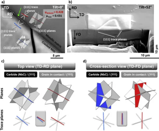
Since all the cracks grow in the metallic matrix along {111} slip planes, the effect of the crystallographic orientations of the metallic grains in contact with the crack tips within NMIs was also inves-tigated. As for the previous crystallographic investigation, no straightforward correlation was observed between the two latter parameters, as because the crystallographic crack path in the metallic matrix is relatively complex (Figs. 3,4,Fig. 6). Therefore, mechanisms of crack transmission in the grains in the vicinity of the pre-cracked NMIs were investigated (Fig. 12c and d). Single slip activity (Fig. 13a) and multiple-slip activity (Fig. 13b) in the grain in contact with the pre-cracked NMIs was observed during LCF testing at room temperature. However, no significant differences were found in the crack growth rate as a function of the number of active slip systems. Clusters of NMIs do not necessarily favors two-slip activities crack growth, as illustrated as example inFigs. 3 and 4. Debonding at the NMI/metallic matrix interfaces was also identi-fied as a crack transition mechanism (Fig. 13d). Some NMIs did not propagate (Fig. 13c). Gray-level contrast with bowtie shape was noticed in the metallic grain adjacent to the crack tip (NMIs), representative of local crystal misorientation (white arrows in
Fig. 13c).
Crack transmission from both sides of the pre-cracked NMIs was documented for all the cracks investigated in the present study (Fig. 14). The three experimental pancakes were found to similarly behave in terms of occurrence of crack transmission mechanisms. However, some differences were found between the two pre-damage modes. As mentioned previously, the tensile pre-pre-damage
condition favored crack propagation from NMIs, leading to a lower fraction of “non-propagating NMIs” compared to the micro-indentation pre-damage condition, and inversely to higher frac-tions of the three other mechanisms to transmit damage: (i) NMI/ metallic matrix debonding, (ii) propagation - single, and (iii) propagation - multiple. In addition, those three latter conditions were shown to be equally distributed for the tensile pre-damage condition, with a slightly higher fraction for the crack mechanism involving a single slip activity in the adjacent grain. For the micro-indentation pre-damage condition, the NMI/metallic matrix debonding mechanism was found to be statistically less repre-sented than the two other propagating mechanisms. No correlation was also found between the mechanism of crack transmission and the overall length of the crack.
To understand non-propagation from pre-cracked NMI, it was previously demonstrated that 3D information of the NMI morphology is needed, especially its extent into the sub-surface. Therefore, the three different mechanisms for crack propagation were investigated in terms of crystallographic configurations be-tween the NMI (crack or interface) and the {111} active slip planes in the adjacent grain.
For the NMI/metallic interface debonding condition, two different crystallographic conditions were found depending on whether the NMI was a nitride (Fig. 15) or a carbide (Fig. 16). The NMI/metallic grain interface correspond to NMI crystallographic planes, i.e. {001} planes and {111} planes for the nitrides (Fig. 15a and b) and carbides (Fig. 16a and b), respectively. It is worth reminding that the [001] is the orientation with the highest stiff-ness for NMIs, making {001}NMI/{hkl}metallic grain interface a
particular location of stress concentration. It was found that a low misorientation of the {111} active slip plane of the adjacent metallic grain is required to initiate debonding for both nitrides and car-bides. The active slip plane in the adjacent metallic grain does not necessarily need to be the highest Schmid factor of the grain ac-cording to the loading direction, and could be as low as 0.243, due to the local stress concentrations that arise due to the presence of the hard, angular particles. However, the {111} active slip plane parallel with the interface at the surface should not necessarily be parallel to the NMI/metallic grain interface in the volume. This active slip plane has to be transgranular within the metallic grain
Fig. 7. Morphological investigation of cracks and NMIs from surface observations of the three experimental pancakes after 10,000 cycles for the two pre-damaging conditions: a) pre-damaged by tensile, b) pre-damaged by micro-indentations. Isolated NMIs were differentiated from cluster of NMIs. No significant trends were correlated between the size of the pre-cracked NMIs and the length of the crack propagating within the surrounding metallic matrix, based on surface observations.
Fig. 8. Serial FIB cross-sections of a cracked carbide. a) Top view of the area of interest before FIB investigation (loading direction along the RD direction). a-h) Serial cross FIB sections at different locations. The Top left corner incrustation illustrates the location of the cross section according to the top view observation. White arrows in d) and e) evidence the presence of a cracked sub-surface carbide. White arrows in f) and g) highlight the change in cleavage plane within the inclusion.
adjacent to the NMI, with a wide range of misorientation angles possible in the volume (Fig. 15d andFig. 16d).
For the propagation conditions with one or at least two slip planes, the activated slip planes generally correspond to planes with relatively high Schmid factor according to the loading direc-tion, but not necessarily the highest Schmid factor of the grain. For propagation conditions involving one slip plane, the active plane generally corresponds to the {111} plane having the highest Schmid factor and with a value as high as 0.4, as depicted inFig. 17a. In rare cases, non-maximal and relatively low Schmid factor planes (
m
ac-tive¼ 0.15sm
max) lead to crack transmission. However, the origin ofsuch an unexpected crack transmission was not found at this point. For propagation conditions involving at least two slip planes, the active planes generally have surface trace planes highly misor-iented and comparable Schmid factors, as shown inFig. 17b. 3.2.5. Evolution of pre-cracked NMIs in the volume after the tensile-pre-damage condition
Surface and sub-surface observations of the pre-cracked NMIs for tensile pre-damage conditions clearly demonstrated the detri-mental contribution of surface and sub-surface clustered NMIs on the crack propagation capability (Figs. 9and10). This is particularly true when cracks run between the individual NMIs in the cluster, making them an effectively much larger inclusion. Therefore, serial polishing was performed, followed by SEM observations in order to statistically document the fraction of pre-cracked NMIs at different depth locations in the volume of the tensile specimen, from the surface down to 210
m
m in the volume (Fig. 18). At least two hun-dred NMIs were randomly observed at each depth location, and the nature of the NMIs was also taken into account for this analysis. It is worth noting that pre-cracked NMIs means cleaved NMIs, the NMI/ metallic grain debonding condition being impossible to captureeven at high magnification. It was shown that around 38% of the NMIs were cracked at the surface, with a slightly higher fraction for the carbonitrides. This fraction of pre-cracked NMIs slightly increased in the volume at a depth of 10
m
m and then decreased up to a stabilized fraction at 50m
m for the nitrides and 90m
m for thecarbides and carbonitrides. While the fractions of cracked NMIs were mostly equivalent at the surface regardless the nature of the NMIs, the stabilized fraction of cracked nitrides is lower (5%) than the one of the carbides and carbonitrides cracked in the volume (16e18%). It is worth mentioning that NMIs debonding could not be documented with this observation technique.
4. Discussion
Understanding the first steps of crack propagation from non-metallic inclusions (NMIs) is essential in order to document the variability in fatigue life experienced by the direct aged version of the Inconel 718 (Ref. [6]). In this study, a particular attention was paid to crystallographic and three-dimensional morphologies of the NMIs and the surrounding grains to correlate to crack growth capability from cracked NMIs. Three experimental pancakes were forged in order to produce microstructures leading to variability in LCF lifespan, i.e. low
d
-phase content (fd-phase<3.2%) and grain sizemicrostructure finer than 15
m
m (Ref. [6]). These experimental wrought pancakes, previously studied in the very high cycle fatigue (VHCF) regime/very low macroscopic elastic deformation region (ref. [7]), were tested in the present study at room temperature in the low cycle fatigue regime. In order to avoid the incubation time associated with crack initiation within NMIs, two methods for pre-cracking NMIs were investigated. As for VHCF testing, pre-straining in the early plastic domain, i.e. “overloading”, prior to fatigue testing favored crack propagation due to longer cracks in general,Fig. 9. Surface and cross-section observations of: a and b) a small at the surface but deep carbide leading to crack propagation, c and d) a non-propagating coarse at the surface but shallow carbide.
but also promote interfacial debonding of the NMIs (Fig. 14). NMIs predominantly failed in a brittle manner along {001} and {011} cleavage planes (Fig. 1), regardless of the pre-damage method. Furthermore, some NMIs naturally cracked beyond stresses of 800 MPa, i.e. 63% of the maximal cyclic stress. The cracking history of NMIs as a function of the cyclic stress likely has a significant influence on subsequent crack growth, as reported in Refs. [6,7]. The earlier the NMIs crack in the cyclic life, the sooner strain localization within slip bands would develop in the vicinity of the crack tip, leading to an opening of the crack within the NMI. The intense local plasticity in the metallic matrix at the opened crack tip might favor crack transmission via the activated slip systems since irreversible deformation was already present due to the pre-damage procedures.
Despite crystallographic failure within NMIs, no correlation was found between the orientation of the pre-cracked NMI and the propagating crack length in the neighboring grains (Fig. 12a). NMIs were as large, and in some cases even larger, than the surrounding grains. Since the elastic and plastic anisotropy for nickel-based superalloys and the difference in elastic and plastic behaviors be-tween NMIs and the metallic grains is important, the heteroge-neous strain/stress field at the grain scale might participate to the complex and unpredictable failure of NMIs involving several cleavage planes (Fig. 1). Therefore, a cracked NMI may or may not propagate into the surrounding grains, independent of its crystal-lographic orientation due to neighborhood effects (Fig. 12a).
Fig. 10. Morphological influence of cracked NMIs from a, c) surface and b, d) FIB-cross section observations on the crack length after 10,000 cycles of the PAN-1&2 microstructure pre-damaged by a, b) tensile and c, d) micro-indentation. Clustering effect and the depth of pre-cracked NMIs were found to have a major contribution in the ease of short crack propagation.
Fig. 11. Crack path length as a function of the stress intensity factor after 10,000 cycles of the PAN-1&2 microstructure for the two ways to pre-damage NMIs (smax¼ 1375 MPa). Comparative effects of the stress intensity factor and the depth of
the pre-cracked NMIs were found to predict the ease of crack propagation. Secondary effects, such as crystallographic effects, are expected to account for the variability in the results.
Furthermore, the crystallographic orientation of the grains adjacent to the cracked NMIs did not have a straightforward rela-tionship to the ease of crack propagation from the NMI into the surrounding metallic grains (Fig. 12b). Indeed, for the testing con-ditions investigated, four different mechanisms of crack trans-mission were found, (i) no propagation, (ii) NMI/adjacent metallic grain interfacial debonding and, transgranular propagation within the adjacent grain involving (iii) along one slip plane, and (iv) at least two slip planes. Because of this variability in mechanisms of crack transmission, specific crystallographic and morphological criteria were found necessary to activate one specific mechanism. A detailed discussion on the crystallographic and morphological considerations is presented in the following sections.
Based on the present systematic investigation of crack propa-gation from non-metallic inclusions (NMIs) in IN718DA and pre-vious studies [6,7,29], detrimental microstructural features were identified and could be taken into account for further design improvement of fine-grain Ni-based IN718DA superalloys (ASTM 9 to 12, i.e. less than 15
m
m in grain size). It is worth noting that IN718DA superalloys demonstrate higher fatigue performances than standard IN718, but with a greater fatigue life variability thatlimits the proper use of this high performance material. Probabi-listic approaches are thus useful lifing methodologies to take into account such a variability in the actual design of structural com-ponents made of IN718DA. While surface and sub-surface NMIs could not be avoided when manufacturing structural components (NMIs nucleate/grow during melting stages of the ingots), mastering NMIs size, their morphology and distribution within wrought components appear necessary to avoid discrepancy and variability in the fatigue life. Large NMIs (i.e. larger than the coarser metallic grains), regardless of their chemical nature (NbC, TiN and NbCTiN), are prone to early crack initiation and propagation into the metallic matrix, leading to abnormally short fatigue life [6,7]. Therefore, refining grains to gain in fatigue performance requires the concomitant refinement in NMIs. NMIs refinement could be obtained during the ingot remelting, the forging operations but also using addition-elements. In addition, NMIs clustering was also found particularly harmful for crack propagation as long as the original cracked NMI within the cluster is large enough and sur-rounding NMIS close enough to propagate a crack. Therefore, the conjunction of large NMI plus NMIs clustering is thought to be the worst microstructural configuration leading to abnormally and
Fig. 12. Correlation between the crystallographic orientation of a, b) the cracked NMIs or c, d) the grain in contact and the crack length (C.L.) for the three experimental pancakes after 10,000 cycles for the two pre-damaging conditions. No correlation was found between neither the initial orientation of the NMI or the orientation of the grain in contact and the crack length despite NMIs cleavage according to {001} and {011} crystallographic planes.
unpredictable short fatigue life. Macrosegregations, at the origin of such NMIs clustering, have to be avoided for the manufacturing of fine-grain Ni-based superalloys and multiple vacuum remelting operations are necessary prior to forge such IN718DA grade.
4.1. Morphological effects on the crack propagation capability The NMIs present in these forged pancakes possessed complex and unpredictable morphologies that required full 3D character-ization (Fig. 9). Therefore, sole surface observations of NMIs are not representative for estimating the initial defect size associated with crack propagation. No straightforward correlations were found between the surface dimensions of the NMIs and the crack length propagating from those NMIs (Fig. 7). Indeed, the largest NMIs at the surface result in no propagation, and inversely smaller surface NMIs that extend more deeply into the sub-surface did propagate (Fig. 7a). FIB-cross section analyses were found valuable, giving access to the unpredictable “surface crack length within NMI/NMI depth” ratio (Fig. 9). Cross-section characterizations aimed to improve correlations between the size of the initial crack and the crack length within the surrounding grains (Fig. 11). It was shown that the “no-propagation” condition follow a morphological crite-rion. Indeed, pre-cracked NMIs large at the surface (2c) with limited extension into the depth (a) did not propagate when 2c/a > 3.07, regardless of the size of the NMIs for this specific LCF condition. In addition to this, FIB-cross-section characterization (Figs. 8and15) showed that clustering could not be predictable from solely surface observations. NMI clustering, either sub-surface or surface clus-tering, favored crack propagation, as shown inFig. 10. Denda et al. reported via fractographic analyses a straightforward correlation between the size of surface NMIs (depth of the NMIs) and the fa-tigue life at intermediate temperatures when using remelting techniques in order to lower the content and the size of NMIs in vacuum induction melted IN718 alloy [10]. Recent studies also re-ported that cluster of NMIs in the volume could lead to atypically short fatigue life [6]. NMIs clustering was not a necessary condition to promote abnormally short fatigue life since isolated but deep
Fig. 13. Different crack transmission modes from pre-cracked NMIs to the surrounding metallic grains. a) Single slip activity in the grain in contact, b) multiple slip activity in the grain in contact, c) No propagation in the grain in contact, d) debonding at NMI/grain interface. A void is also present in the vicinity of the crack.
Fig. 14. Illustration of the fraction of pre-cracked NMIs leading to one specific mech-anism of crack transmission in the grain in contact of the pre-crack tip, i.e. No prop-agation, NMI/metallic matrix debonding, propagation with one active slip system, or propagation with at least two active slip systems.
NMIs can also be at the origin of premature cracking under various fatigue conditions (Refs. [6,7]). FIB-cross section characterizations of surface secondary cracks aimed to statistically document morphological requirements of cracked NMIs to promote crack propagation in the surrounding grains, as conventionally docu-mented via fractographic observations of numerous fatigued specimens. In contrast to fractographic analyses, the FIB-cross section characterization allowed for identification of non-propagating configurations, i.e. large cracked NMIs at the surface with limited extension into the depth.
4.2. Crystallographic effects on the crack propagation capability Morphological aspects of pre-cracked NMIs play a critical role in the crack propagation capability under LCF loading conditions (Figs. 9,Figs. 10 to 11). However, discrepancy in the results when solely plotting morphological criteria of the pre-cracked NMIs suggests that neighborhood effects, such as crystallographic con-figurations, are also considerations to take into account. In the LCF regime for such a multiphase material, both the elastic properties at the grain scale and the strain localization within slip bands in the vicinity of cracked NMIs are relevant parameters for the early stages of crack transmission from NMIs. Different mechanisms of crack transmission from cracked NMIs were found in the present inves-tigation, including NMI/metallic grain interfacial debonding and
transgranular crack propagation, and their origin is discussed in more detail below.
For the B1-cubic and A1-fcc crystallographic structures of the NMIs (carbide, nitride and carbonitride) and the
g
-nickel metallic matrix respectively, Young's moduli along the loading direction range from 124 to 318 GPa, 417e556 GPa and 416e579 GPa for the metallic matrix Alloy IN718, TiN and NbC, respectively [30e32]. Due to crystallographic structures, <001> and <111> crystallo-graphic directions correspond to the lowest and highest stiffness for theg
-nickel metallic matrix, respectively. Conversely, <001> and <111> crystallographic directions correspond to the highest and lowest stiffness for NMIs, respectively. The difference in elastic properties between NMIs and the metallic matrix can be as large as 445 GPa at the grain scale, depending on the misorientation tween the two materials. This difference in elastic properties be-tween the two phases is two times higher than the one within the metallic matrix (D
Emax(g
-Ni phase) ¼ 195 GPa). This difference inelastic properties locally leads to stress concentration in the vicinity of these specific configurations, potentially leading to crack initia-tion/propagation under cyclic loading. As illustrated inFigs. 15and
16, blocky nitrides and carbides were demonstrated to have in-terfaces parallel to specific crystallographic planes, i.e. the {001} and {111} planes, respectively. This blocky morphology [7,33] is due to diffusion controlled mechanism of NMIs partitioning elements from the surrounding liquid metal during the solidification process
Fig. 15. Crystal configurations enabling nitride/metallic matrix debonding. The debonded interface is depicted with a green arrow. The {001} and {111} planes and trace planes were illustrated for the nitride and the adjacent metallic grain, respectively. The blue plane and red plane correspond to the plane of the nitride and the metallic grain parallel to the debonded interface, respectively. The Schmid factor of the active {111} plane according to the loading direction (horizontal direction) is relatively low. a) Surface observation showing that the debonded nitride/metallic matrix interface correspond to a {001} trace plane of the nitride and that the {111} trace active slip plane in the adjacent grain is parallel to the interface. b) FIB cross-section observation of the nitride demonstrating that nitride/metallic matrix interfaces also correspond to {001} planes in the volume. This figure also depicts a sub-surface cluster of nitrides not visible via surface observations. Crystal configurations demonstrating the c) necessary low misorientation angle between the {001}nitride
and the {111}metallic grainat the surface, and d) not necessarily low misorientation angles between the {001}nitrideand the {111}metallic grainin the volume for the debonding condition.
[33e35]. It was demonstrated in the present study that when there is alignment of the {001}TiNor {111}NbCplane and a {111}g-matrix metallic grain, interfacial debonding was a possible crack initiation
mechanism leading to crack propagation in the surrounding metallic grains (Figs. 13,15 and 16). Both the deformation in-compatibility at this interface and the potential plastic activity parallel to this interface favor the occurrence of this debonding
crack transmission mechanism. Interestingly, overload prior to LCF testing was reported to weaken such interface and promote this cracking mechanism from pre-cracked NMs pre-strained in the early plastic regime (Fig. 14). Accumulation of plastic deformation at the NMIs/metallic grain interface under cyclic loading was re-ported in the literature via finite element calculations [36,37]. In addition, thermal strains in the metallic matrix surrounding
Fig. 16. Crystal configurations enabling carbide/metallic matrix debonding. The debonded interface is depicted with a green arrow. The {111} planes and trace planes were illustrated for both the carbide and the adjacent metallic grain. The blue plane and red plane correspond to the plane of the carbide and the metallic grain parallel to the debonded interface, respectively. The Schmid factor of the active {111} plane according to the loading direction (horizontal direction) is relatively high and close to the maximal Schmid factor value. a) Surface observation showing that the debonded carbide/metallic matrix interface correspond to a {111} trace plane of the carbide and that the {111} trace active slip plane in the adjacent grain is nearly parallel to the interface. b) FIB cross-section observation of the carbide demonstrating that carbide/metallic matrix interfaces also correspond to {111} planes in the volume. Crystal configurations demonstrating the c) necessary low misorientation angle between the {111}carbideand the {111}metallic grainat the surface, and d) low
misorientation angle between the {111}carbideand the {111}metallic grainin the volume for the debonding condition. (For interpretation of the references to color in this figure legend,
the reader is referred to the Web version of this article)
Fig. 17. Propagation condition from a cracked NMI involving a) one active slip plane with a relatively high Schmid factor (mactive¼mmax¼ 0.492), b) at least two slip planes with a
carbides following standard heat treatments were reported in the literature using high resolution EBSD techniques [16,38]. Such thermal strains result from the difference in thermal expansion properties between NMIs and the metallic matrix, NbC experi-encing higher difference in coefficient of thermal expansion (
a
NbC¼ 6.6 % 10#6!C#1 [39]) with IN718 (a
IN718¼ 13 % 10#6!C #1[40]), compared to TiN (
a
TiN¼ 9.3 % 10#6!C#1[39]). After cyclingloading, high geometrically-necessary dislocation (GND) density and deformations were found in the vicinity of carbides, resulting in carbides/metallic matrix debonding in some cases [16]. Beyond this strain localization phenomenon at the interface due to high difference in elastic-plastic behavior between the two media, partially debonded non-metallic inclusions embedded in a metallic matrix subjected to cyclic loadings were shown more damaging than a pre-cracked NMIs [36,37,41,42]. In the present study, the interfacial debonding mechanism did not necessarily promote longer cracks since the slip transfer from metallic grain to metallic grain is also an important parameter to take into account for short crack propagation [43].
For transgranular crack propagation (single and multiple), in-situtensile and fatigue testing demonstrated that NMIs easily crack under uniaxial loading in the early plastic regime at room and in-termediate temperatures, but plasticity transmission or crack growth does not easily result from pre-cracked NMIs to the sur-rounding metallic grains under monotonic or cyclic loading [6,7,44]. However, strain localization in the vicinity of NMIs in nickel-based superalloys was also evidenced via high resolution-digital correlation (HR-DIC) techniques, showing intense slip ac-tivities in regions subjected to strain concentration due to morphological consideration of biphasic materials, i.e. convex angular regions [29,45e47]. Intense deformation localized within slip bands in these regions also highlights the potential occurrence of transgranular cracking in the grain adjacent to the NMIs, espe-cially when NMIs are pre-cracked.
5. Conclusion
The short crack propagation behavior of the IN718DA alloy from non-metallic inclusions (NMIs) was investigated under low cycle
fatigue conditions at room temperature. Both crystallographic and morphological considerations were taken into account in order to document the capability of cracked brittle NMIs to transmit crack in the surrounding metallic matrix. Some conclusions from the pre-sent work are detailed below:
- Two methods for pre-cracking NMIs, pre-straining in uniaxial tension and micro-indentation, were investigated to avoid the crack initiation incubation time during low cycle fatigue. NMIs cracked in a brittle manner along a combination of {001} and/or {101} cleavage planes, regardless the pre-damage condition. - NMIs clustering at the surface or slightly sub-surface in the
volume increased the crack propagation capability from pre-cracked NMIs. FIB-cross sections were essential for quantifica-tion of clustering.
- Four different crack propagation scenarios for pre-cracked in-clusions were observed: (i) no propagation, (ii) NMI/metallic matrix interfacial debonding, transgranular propagation involving (iii) one slip plane, and (iv) at least two slip planes. The tensile pre-damage condition favors crack propagation (lower fraction of the no-propagation condition and longer cracks) and also the interfacial debonding mechanism due to a greater de-gree of plasticity in the surrounding grains.
- The conditions for “no propagation” were associated with a crack length/crack depth ratio higher than 3.
- For the debonding condition, differences were found for car-bides and nitrides, the interfacial plane being {111} and {100} for the carbide and the nitride, respectively. The active {111} trace slip plane of the adjacent metallic grain have to be parallel (low misorientation required) to the surface trace interfacial plane. - For transgranular propagation, a high Schmid factor according
to the loading direction favors crack propagation involving one active slip plane, while grains having two {111} slip systems with comparable Schmid factors favor crack propagation involving at least two active slip planes, i.e. a zigzag crack propagation. High Schmid factors were shown not to be a necessary condition for the capability of the crack to propagate, as long as the three dimension morphological criterion is fulfilled.
Acknowledgement
The authors are grateful to SAFRAN Aircraft Engines for providing materials and financial support. The authors would like to thank Eric Andrieu from CIRIMAT in France for stimulating dis-cussions on short crack propagation from non-metallic inclusions. The authors are grateful to Stephan Kramers (UCSB) and Florence Hamon (Pprime institute) for help in the FIB characterization and mechanical testing.
Appendix A. Supplementary data
Supplementary data to this article can be found online at
https://doi.org/10.1016/j.actamat.2018.11.051. References
[1] T.M. Pollock, S. Tin, Nickel-based superalloys for advanced turbine engines: chemistry, microstructure , and properties, J. Propul. Power 22 (2006) 361e374,https://doi.org/10.2514/1.18239.
[2] C.T. Sims, A history of superalloy metallurgy for superalloy metallurgists, in: Superalloys 1984, Champion (USA), 1984, pp. 399e419, https://doi.org/ 10.7449/1984/Superalloys_1984_399_419.
[3] A. Pineau, S.D. Antolovich, High temperature fatigue of nickel-base superalloys - a review with special emphasis on deformation modes and oxidation, Eng. Fail. Anal. 16 (2009) 2668e2697, https://doi.org/10.1016/ j.engfailanal.2009.01.010.
Fig. 18. Evolution of the fraction of cracked NMIs as a function of the depth for a pre-strained specimen corresponding to the tensile pre-damage condition.