HAL Id: hal-00732860
https://hal.inria.fr/hal-00732860
Submitted on 17 Oct 2012
HAL is a multi-disciplinary open access archive for the deposit and dissemination of sci-entific research documents, whether they are pub-lished or not. The documents may come from teaching and research institutions in France or abroad, or from public or private research centers.
L’archive ouverte pluridisciplinaire HAL, est destinée au dépôt et à la diffusion de documents scientifiques de niveau recherche, publiés ou non, émanant des établissements d’enseignement et de recherche français ou étrangers, des laboratoires publics ou privés.
A Cooperative Personal Automated Transport System
-A CityMobil Demonstration in Rocquencourt
Paulo Resende, Fawzi Nashashibi, François Charlot, Carlos Holguin, Laurent
Bouraoui, Michel Parent
To cite this version:
Paulo Resende, Fawzi Nashashibi, François Charlot, Carlos Holguin, Laurent Bouraoui, et al.. A Cooperative Personal Automated Transport System - A CityMobil Demonstration in Rocquencourt. ICARCV 2012 - 12th International Conference on Control, Automation, Robotics and Vision, Nanyang Technological University of Singapore, Chinese University of Hong Kong and IEEE Guangzhou Control Chapter, Dec 2012, Guangzhou, China. �hal-00732860�
A Cooperative Personal Automated Transport System
A CityMobil Demonstration in Rocquencourt
Fawzi Nashashibi – IEEE member, Paulo Resende, François Charlot, Carlos Holguin and Michel Parent
IMARA Team INRIA Rocquencourt, France {fawzi.nashashibi, paulo.resende, francois.charlot}@inria.fr Laurent Bouraoui Robotics Center Mines ParisTech Paris, France Laurent.Bouraoui@mines-paristech.fr
Abstract—This article tackles the problem of the autonomous navigation and coordination of multiple driverless vehicles for the transport of persons or goods in outdoor environments. The system composed of fully automated road vehicles, capable of providing an effective transportation service, was recently tested at the city of La Rochelle. This same system was further improved, and a new demonstration was performed at Inria Rocquencourt, in order to demonstrate the validity of the concepts for a coordinated navigation in the presence of ambiguous and conflictual situations in a mixed environment. The originality of the approach relies on the use of new cooperative concepts and their combination with advanced perception tasks operating simultaneously on several robots. This system was developed in the context of the European project CityMobil.
Keywords—CityMobil, Cybus shuttles, cooperative navigation, vehicle coordination, intelligent transportation, urban transport.
I. INTRODUCTION
The main objective of the CityMobil project was to design and develop new advanced concepts for efficient urban transportation capable of reducing energy consumption, optimizing used space, reducing pollution, improving security, comfort and quality of living. In order to educate the urban population to these concepts, scrutinize public acceptance and evaluate new transport modes in actual operating conditions, the project introduced systems composed of fully automated vehicles in the heart of some pilot cities bringing them closer to public observation.
It was in this context that between May and July 2011, Inria putted into service an on-demand door-to-door transport system in the city of La Rochelle [1], using fully automated electric and communicating road vehicles, better known as cybercars [2]. These cybercars were demonstrated to the city population and their performance evaluated during the period of 3 months service. This demonstration showed how autonomous road vehicles can be effectively used in public transport, especially in low to medium demand areas and periods, to make the public transport service more reliable and frequent where conventional collective public transport cannot meet the mobility needs of the population in an environmentally and economically sustainable manner.
A new demonstration, organized after the end of the service in La Rochelle, was performed to validate the concept of collaboration between autonomous vehicles. This paper presents this new demonstration that took place at Inria’s Rocquencourt campus in November 2011. As in La Rochelle, this site has presence of pedestrians and limited road traffic. However, unlike La Rochelle, Inria’s campus is a private site with restricted access conditions. Therefore, this extended demonstration was not accessible to the general public.
The paper is composed of two main sections: the first will describe the system architecture from both the vehicles and the infrastructure elements. The second section will describe the operational aspects on the site. Results and conclusions will be provided at the end of the paper in the section III.
II. SYSTEM ARCHITECTURE
A. Overview
An on-demand door to door transportation service accessible to all the users of the INRIA Rocquencourt campus was implemented using fully automated electric and communicating vehicles. The vehicles behavior is similar to a horizontal elevator that can be called from a station and serve multiple destinations.
The monitoring and coordination of the vehicles was performed by a vehicles management system (VMS) through a dedicated wireless IPv6 mesh network [3].
B. Site description
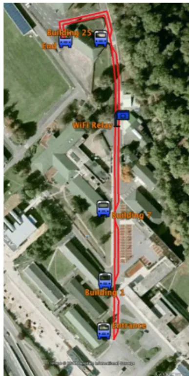
The demonstration site is a 365 m long two-lane road, where of 5 stations equipped with specially conceived wireless routers were installed.
The distance between the stations is as follows: Stop 1 (Entrance) – Stop 2 (Building 1): 50m Stop 2 (Building 1) – Stop 3 (Building 7): 70m Stop 3 (Building 7) – Stop 4 (Building 25): 155m Stop 4 (Building 25) – Stop 5 (End): 90m
In order to guarantee the wireless coverage over the whole site, an additional wireless router installed between Stop 3 and Stop 4, and served as a relay. For practical reasons, the “End” stop was not used during the demonstration.
All the stations are located in only one side of the road, to maintain the same site configuration that was implemented in La Rochelle, due to its physical infrastructure constraints (not enough space for the vehicles to turn around in both ends).
The Figure 1 shows an aerial view of the demonstration site.
C. Stations
Five stations where installed in the demonstration site where the users could call a vehicle via a touch screen interface. This screen also provided information such as the vehicles availability or the pick-up arrival time. All the stations where equipped with a wireless IPv6 communication device with corresponding antenna that relayed the data exchanged between the stations, vehicles and the vehicles management center.
Additional wireless relays needed to be added between some of the stations to have full coverage of communications in the demonstration area. These stations are installed only on one side of the road, forcing the vehicles to change lanes in order to approach the station platform.
D. Vehicle Platform
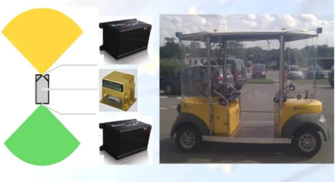
The vehicles, named Cybus, are represented on Fig. 2. These vehicles have the capacity to transport 4 or 5 seated persons at an average speed of 8 km/h and with a maximum
speed of 12 km/h. They are basically the same than the ones used during the demonstration of La Rochelle in 2011.
Thanks to the gained experience during the 3 months of this demonstration, the vehicles were modified in order to improve control, localization and safety.
1. Control
During the La Rochelle demonstration, tedious oscillations were noticed when the Cybus was moving on long straight trajectories. After numerous trials and experiments, it has been shown that the low-level control algorithm was not responsive enough and that the current implementation was error-prone. Once this incorrect behavior was identified, the control system has been reviewed and re-configured in less than a day thanks to the highly modular design of the whole hardware/software system.
2. Localization
Initially the localization and obstacles detection tasks were performed by using the same 2 Ibeo Alasca XT laser sensors connected to a single fanless computer via an Ibeo ECU dedicated to read, synchronize, calibrate and merge the lasers data. This configuration used during the demonstration in La Rochelle highlighted some problems that were not experimented before.
First of all, the whole system needed to be restarted too often due to the lack of reliability of the ECU. Despite different changes in the ECU configuration, it was not possible to solve this problem with such kind of sensor configuration.
In addition, the laser based SLAM method [4] was not able to find the vehicle position in a very crowded environment. This was due to the obstruction of the lasers by people surrounding the vehicle as the lasers position was at less than 1 meter from the ground. In such situation, the current local map cannot match the recorded global map.
To solve these problems, a new sensor and processing configuration was implemented: two Ibeo Lux laser scanners, connected to a dedicated computer, have been integrated on the roof of the Cybus (around 2m height) at the front and at the rear ends. They provided from 2 to 4 layers range data with a maximum view angle of 110° and a maximum range of 200
Fig 2. Cybus vehicles at Inria Rocquencourt
Fig 1. Inria Rocquencourt demonstration map: route and stations
meters. The scan frequency goes from 12.5Hz up to 50Hz. With this configuration, these laser sensors are used only by the localization module and are no longer affected by the presence of people around the car.
The pose obtained by the SLAM was fused together with odometry and inertial measurement unit (IMU) data by the means of an EKF to improve the accuracy of the vehicle localization.
A RTK (Real Time Kinematics) GPS has also been integrated into the vehicle to provide ground truth and to evaluate the accuracy of the localization.
3. Safety
Autonomous vehicles may need to stop in a progressive way in the case of obstacles in the way, or to stop immediately in the case of an imminent collision or sudden vehicle malfunction. It is for those reasons that the Cybus vehicles are equipped with several safety devices, managed by the high-level software as well as by the low-high-level embedded electronics.
In the low-level, five emergency stop buttons, connected in series and arranged on each side of the vehicle and near the control screen, may be pushed at any time to immediately bring the vehicle to a full stop. Furthermore, each vehicle has a retractable front bumper with two emergency switches. These two switches are also connected in series with the emergency buttons. Finally, every vehicle is equipped with a radio-controlled emergency cut-off remote of category 3 according to the French norm NF EN954-1for safety devices.
An emergency stop is activated when the emergency remote button is engaged or there is a loss of communication between the remote and the vehicle. The activation of the emergency stop implies the cut off the power supply of the drive components and the release of the vehicle parking brake, resulting in an immediate stop.
In the high-level software, obstacle detection is performed using 2 Alasca XT lasers scanners connected to an Ibeo ECU. The algorithm of detection defines a customizable safety area, depending among others on the driving direction, the speed and the dimensions of the vehicle. In the present of objects in this safety area, the vehicle will decrease its speed and eventually
stop if the object gets closer to the vehicle. The lack of reliability of the Ibeo ECU still caused some problems to the system, but the system safety was not greatly affected.
E. Communications
Communications are an essential element in automated systems. They allow the cooperation between systems by the exchange of relevant information for an augmented perception, planning and control of these systems.
By means of communications we can have for example, more consistent and complete local and global maps, data collection, user requests management and anticipation, avoids unnecessary stops and deadlocks, or improves the traffic flow.
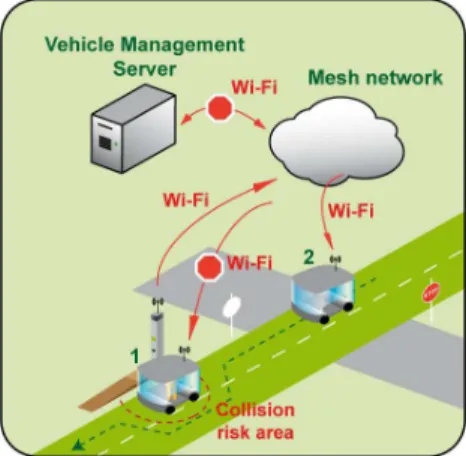
A specific multi-hop Mobile Ad hoc Network (MANET) was used to perform V2V and V2I wireless communications using standardized modules compliant with the IPv6 protocol. These modules where packaged into a dedicated hardware called Cube that was specially designed and conceived for ITS applications. The Cubes, shown in Figure 4, form the nodes of the mesh network. They handle all the data exchanged between the automated vehicles and the infrastructure elements such as the stations or the control center (VMS).
The Cube is a Linux embedded PC with 2 mini PCI communication cards. The radio frequency used was in the licensed ITS band of 5.9 GHz of the standard 802.11p for wireless access in vehicular environments (WAVE). The implemented services discovery based architecture provided an IPv6 network based on a B.A.T.M.A.N. mesh network and a Cables framework that manages the services.
The diagram in Figure 5 is a representation of the mesh network and the data quality in the links between nodes.
Fig 5. Mesh network diagram
Fig 4. Cube communications hardware
Fig 3. Cybus sensors configuration
All traffic is encapsulated and forwarded until it reaches the destination, hence emulating a virtual network switch of all nodes participating. Therefore, all nodes appear to be a local link and are unaware of the network's topology and are unaffected network changes.
F. Vehicles Management System
The Vehicle Management System (VMS) it is an application handles the stations requests, the conflict areas and monitors the automated vehicles. The information about the state of these vehicles is stored in a pool and kept up to date by the VMS. The knowledge of the vehicles environment is limited to the conflict areas (mainly the stations) and the vehicles path. From the VMS an operator can stop all the vehicles at once. In this implementation the management of the stations and vehicles is centralized. Certain decisions such as the coordination between 2 vehicles could be decentralized with one of them taking the leading role and making the decision.
The VMS, represented in Figure 6, is composed of two distinct parts:
A web server that provides a user interface to the operator and stations, and an API that allows a vehicle to be called from the station or by a mobile device.
A server that communicates with the vehicles using a library called Cables.
The interface between the two applications is done through a common database.
1. Station calls management
Vehicle calls at the stations are done through the stations graphical interface and are stored in a central database. These dynamic web pages are handled by the VMS. Once there is a new call in the database the attribution of the station to a vehicle it is done by choosing the vehicle closest to the calling station and that, preferably, already travels in the direction of that station. Then, the VMS sends the station position as a new destination the selected vehicle that will add it to its destination queue in the correct order.
2. Vehicles management
A server communicates directly with the vehicles. This server monitors and manages the vehicles priorities when
approaching conflict areas (e.g. stations) and when overtaking other communicating vehicles.
By setting priorities to access a conflict area and by automatically redistributing the vehicles along the network according to the demand it avoid deadlocks and optimizes the vehicles availability time. If only obstacle detection was used and no coordination was performed, deadlocks would happen. Besides, by doing an automatic redistribution of the vehicles, the waiting time is reduced in the stations with the highest demand.
3. Supervision
The VMS allows an operator to monitor and partially control the entire fleet of vehicles, stations and communications network. For example, an operator can send a command to stop or slow down all vehicles. The stations web-based graphical interfaces can be modified directly by the operator to display some specific information to the users at specific station. Through the VMS the operator can also see the status of the secured wireless mesh network and perform the adequate action in the case, for example, of a faulty node.
The operator can always override the automatic supervisor of the VMS. For example, the operator may disable all overtaking manoeuvres, or send predefined destinations to a specific vehicle (e.g. depot or charging station).
Through a web interface an operator could easily monitor the status and position of all the vehicles in the network.
III. SYSTEM OPERATION
The demonstration performed at the INRIA Rocquencourt campus consisted of an on-demand door-to-door transport service using two Cybus, .in a circuit with two lanes with opposite traffic directions like represented in the following figure:
The station’s where positioned in only one side of the road that leads to conflictive situations between the vehicles. The
Fig 7. Two lane traffic schema at INRIA Rocquencourt
Fig 6. VMS architecture
capability to automatically identify and manage these situations was integrated in the VMS.
Several scenarios of conflicts between the driverless vehicles and other non-communicating obstacles were considered but only partially solved. An example of these conflicts is the presence of a truck or pedestrian obstructing the vehicle path. To solve this scenario in an optimal way a more complex set of sensors, then the one available in the vehicles would be required. In particular, it would be necessary to determine the type of obstacle and its properties (e.g. length, speed) so that the driverless vehicle could perform the adequate overtaking manoeuvre respecting at the same time the road traffic rules. With the current implementation and given the previous situation, the Cybus would just stop before the obstacle and wait for further instructions from the VMS.
The conflict management between the communicating driverless vehicles was centralized in the VMS although the vehicles add enough intelligence on board to solve these types of conflicts by themselves.
In order to automatically redistribute the automated vehicles in the circuit it would be necessary to know the vehicles occupancy and the doors status (closed or opened).
In the absence of these features the vehicles where redistributed by an operator inside the vehicle.
Some representative conflict scenarios between communicating driverless vehicles were identified and solved:
1. Vehicle stopped at station
In this scenario, a vehicle 2 is stopped at a station.
In the situation where another vehicle 1 goes to the same station where vehicle 2 is stopped, the VMS will order the vehicle 1 to stop and wait for vehicle 2 to leave the station before allowing it to resume its movement. See Figure 8-a.
In the situation where vehicle 1 passes, without stopping, to the station where vehicle is stopped, the VMS will order vehicle 2 to remain stopped at the station and wait for vehicle 1 to pass. See Figure 8-b.
2. Vehicle leaving station
In this scenario, a vehicle 1 is leaving a station. Another vehicle 2 needs to stop until vehicle 1 has left the station by
making a lane change maneuver. Only after this vehicle 2 can advance to the free station.
3. Vehicle arrive to the same station
In this scenario, a vehicle 1 and a vehicle 2 drive at the same time towards the same destination station. In this case, the VMS will determine, based on the proximity, which vehicle will have the priority. The closest vehicle will be allowed to continue and dock at the station, while the other vehicle will be ordered to stop and wait.
4. Vehicle arrive to the same station
In this scenario, a vehicle 2 has to overtake a vehicle 1 stopped in the same lane (not necessarily at a station). In this case, the VMS will provide vehicle 2 the authorization to overtake and order vehicle 1 to remain stopped until vehicle 2 has finished the overtaking manoeuvre. The vehicle 2 will then overtake vehicle 1 based on the information that vehicle 1 provides (e.g. pose and dimensions).
Fig 10. Vehicle 1and vehicle 2 arriving in the same station Fig 9. Vehicle 1 leaving station and vehicle 2 going to that same
station
IV. CONCLUSION
We presented in this paper the extensions done at the Inria Rocquencourt demonstration for the European project CityMobil that allowed the collaboration between driverless vehicles. These modifications were made to the vehicles management system and certain elements of vehicles architecture to allow the vehicles cooperation. These vehicles were the same used in the on-demand personal automated transport system previously demonstrated in La Rochelle also for the CityMobil project.
The consecutive successful technological demonstrations performed and the very positive public acceptance demonstrates that these systems are a valid mobility solution for the cities of tomorrow and can already be used in today’s private sites.
The vehicles cooperation is performed using a centralized architecture where the VMS plays the decisional role. The VMS communicates with all the operating vehicles and resolves all conflict situations and bottlenecks. However in some situations it may be necessary that the vehicles rely only on their own decisional system especially in case of a VMS shortage or while performing a reactive navigation (e.g. obstacle avoidance or overtaking). We expect to further develop this system and explore the use of a decentralized decision system to solve these later issues.
1. ACKNOWLEDGMENT
This work was supported in part by the European projects CityMobil and CityNetMobil.
2. REFERENCES
[1] L. Bouraoui, F. Charlot, C. Holguin, F. Nashashibi, M. Parent, P. Resende, “An On-demand Personal Automated Transport System: The CityMobil Demonstration in La Rochelle”, Intelligent Vehicles Symposium (IV) 2011, pp. 1086 – 1091, 5-9 June 2011.
[2] M. Parent, “Cybercars: A solution for urban transport”, in CODATU Conference, 2004.
[3] J. Choi, Y. Khaled, M. Tsukada and T. Ernst, "IPv6 support for VANET with geographical routing", 8th International Conference on Intelligent
Transport System Telecommunications (ITST 2008), Phuket, Thailand, 22 October 2008.
[4] J. Xie, J. Xie, F. Nashashibi, M. Parent, O. Favrot, “A real-time robust global localization for autonomous mobile robots in large environments”, ICARCV 2010: 1397-1402.
Fig 11. Vehicle 2 overtakes stopped vehicle 1