HAL Id: hal-00836324
https://hal.archives-ouvertes.fr/hal-00836324
Submitted on 20 Jun 2013
HAL is a multi-disciplinary open access
archive for the deposit and dissemination of
sci-entific research documents, whether they are
pub-lished or not. The documents may come from
teaching and research institutions in France or
abroad, or from public or private research centers.
L’archive ouverte pluridisciplinaire HAL, est
destinée au dépôt et à la diffusion de documents
scientifiques de niveau recherche, publiés ou non,
émanant des établissements d’enseignement et de
recherche français ou étrangers, des laboratoires
publics ou privés.
A generic synthetic image generator package for the
evaluation of 3D Digital Image Correlation and other
computer vision-based measurement techniques
Dorian Garcia, Jean-José Orteu, Laurent Robert, Bertrand Wattrisse, Florian
Bugarin
To cite this version:
Dorian Garcia, Jean-José Orteu, Laurent Robert, Bertrand Wattrisse, Florian Bugarin. A generic
synthetic image generator package for the evaluation of 3D Digital Image Correlation and other
com-puter vision-based measurement techniques. PhotoMechanics 2013, May 2013, Inconnue, France.
pp.Clé USB. �hal-00836324�
A GENERIC SYNTHETIC IMAGE GENERATOR PACKAGE FOR THE EVALUATION OF 3D DIGITAL IMAGE CORRELATION AND OTHER COMPUTER VISION-BASED MEASUREMENT TECHNIQUES
Dorian Garcia1, Jean-José Orteu2, Laurent Robert2, Bertrand Wattrisse3and Florian Bugarin2
1
Computer Vision Consultant, Raleigh, NC, USA
2
Université de Toulouse, Mines Albi, ICA (Institut Clément Ader), 81013 Albi , France
3
LMGC, UMR CNRS 5508, Université Montpellier II, Montpellier, France dorian.garcia@gmail.com, jean-jose.orteu@mines-albi.fr
1. INTRODUCTION
Stereo digital image correlation (also called 3D DIC) is a common measurement technique in experimental mechanics for measuring 3D shapes or 3D displacement/strain fields, in research laboratories as well as in industry. Nevertheless, like most of the optical full-field measurement techniques, 3D DIC suffers from a lack of information about its metrological performances. For the 3D DIC technique to be fully accepted as a standard measurement technique it is of key importance to assess its measurement uncertainties.
In order to quantify the measurement uncertainty of the technique several approaches can be used:
1. modeling of the measurement process and error propagation [1, 2, 3] (note that it is difficult if not impossible to model precisely the whole measurement process),
2. real experiment on a reference test (ground truth real data) and comparison with the measurements obtained by processing the real images [4, 5] (note that it is difficult if not impossible in practice to obtain displacement/strain fields ground truth),
3. virtual experiment using simulated images (ground truth simulated data) and comparison with the measurements obtained by processing the simulated images [6, 7].
To quantify the measurement uncertainties of 3D DIC through a virtual experiment approach, and following the ap-proach already developed to assess the measurement uncertainties of the 2D DIC technique [8, 9], we have developed a software that generates a set of synthetic calibration images as well as speckle-pattern images of a virtual 3D object (with and without deformation). It uses a procedure that mimics the acquisition process of a real stereovision camera rig. This approach can be used to validate, evaluate and understand how the parameters related to the experimental set-up as well as those related to the 3D DIC code can influence the measurement uncertainties of the 3D DIC technique.
2. OBJECTIVES
For our software package to gain wide acceptance within the community, we believe that all the following requirements must be fulfilled:
• Images. Generate realistic calibration images, as well as images of one or more virtual test objects before and after deformation. The method should support post-processors that can simulate various experimental artifacts such as blur, dust particles on the lenses, or even defective pixels.
• Cameras. Support common camera models, including distortion and depth-of-field effects. Also simulate the effect of pixel fill-factor, noise, and quantization resolution (bits/pixel).
• Objects. Implement the rendering of common calibration objects, and provide a flexible way to define a de-formable test object. Test objects must be no less than G2 continuous (continuous curvature) which rules out
tri-angle/quadrangle meshes.
• Textures. Support the mapping of both real speckle images and computer generated ones [8] onto the virtual test object.
• Lighting. Handle reflectance models permitting the rendering of various lighting effects.
• Ground Truths. Output ground truth data such as 3D displacements, stereo disparities, tracking vectors, depth, pixel noise, distortion, suitable for validating/evaluating every step of a given 3D DIC implementation.
• Availability. Free of charge.
As staggering as all those objectives might seem, there is fortunately a simple technique that allows for their implementa-tion: ray tracing. The next section briefly presents its principles.
3. RAY TRACING
One physically accurate approach to rendering an image of a scene (a collection of objects and lights) consists of emitting many light rays from all the light sources, bouncing them off into many more light rays according to the reflectance distribu-tion of the objects they eventually hit, until they eventually strike the image plane. This naive approach is computadistribu-tionally prohibitive because only a tiny fraction of the original light rays will eventually hit the sensor plane and hence contribute to computing the overall scene radiance as seen by each pixel. This approach is referred as forward ray tracing.
A solution to this problem was published by Turner Whitted [10]: instead of tracing rays from the light sources, he proposed to shoot them off the camera. Each ray emanating from the camera, called a primary ray, is then checked against all scene objects for intersections. If intersections exist, the one closest to the camera optical center is retained and shading is performed to evaluate the radiance at the ray/object intersection. The shading process of a given object point consists of firing up new rays toward each light source to determine whether it is shadowed by another object, or directly lit — those rays are called shadow ray. A reflectance model is then applied to determine the contribution of each light source to the radiance of a given point with respect to the origin of the ray. This process can also simulate the reflection and refraction of rays according to the material properties of the object and laws of reflection and refraction by shooting
secondary rays. Whitted’s method is sometimes referred to as backward ray tracing, or, more often, simply as ray tracing.
A thourough treatment of this standard computer graphics algorithm can be found in [11].
The ray-tracing method is not only surprisingly simple in its principles, it also provides its implementers with the liberty to choose: (1) any camera model, as long as one can generate primary rays for each pixel; (2) any object for which one can compute the intersection, if any, of a ray with its surface; (3) any reflectance model, provided that one can compute their required quantities such as the surface normal of an object at any given point for certain models; (4) any texture, as long as one can provide a means to map them to the surface of an object.
Sampling artifacts can also be mitigated in a simple manner by firing up several primary rays for each pixel, randomly sampling the pixel sensitive area (akin to the so called fill-factor), and averaging each computed radiance. While this stochastic ray tracing process cannot guarantee the absence of any residual aliasing, those are converted to noise [11]. This noise decreases as the number of randomly distributed samples increases, and so does the rendering time.
4. SOFTWARE PACKAGE
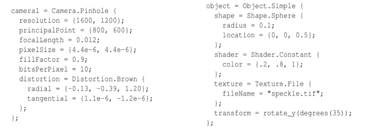
We have implemented a software package based on the ray-tracing technique that fulfills all the requirements enumerated in the second section. Our solution is designed around a generic architecture that can be easily extended to support new features such as other camera models, calibration targets, objects, reflectance models, image post-processors, light sources, and ground truth outputs. It uses an ad hoc declarative language for describing a virtual experiment — see fragment of code in Fig. 1.
camera1 = Camera.Pinhole { resolution = {1600, 1200}; principalPoint = {800, 600}; focalLength = 0.012;
pixelSize = {4.4e-6, 4.4e-6}; fillFactor = 0.9;
bitsPerPixel = 10;
distortion = Distortion.Brown { radial = {-0.13, -0.39, 1.20}; tangential = {1.1e-6, -1.2e-6}; }; }; object = Object.Simple { shape = Shape.Sphere { radius = 0.1; location = {0, 0, 0.5}; }; shader = Shader.Constant { color = {.2, .8, 1}; }; texture = Texture.File { fileName = "speckle.tif"; }; transform = rotate_y(degrees(35)); }; h
Figure 1 - Fragments of sample code for describing a scene.
4.1 Camera and Distortion Models
The camera models currently supported include the classic pinhole equations augmented with Brown’s radial and tangential distortion terms [12, 13], as well as a thin lens model using the aperture size and the distance of the plane in focus. As previously mentioned, new camera models can easily be incorporated into our software, should the need emerge, such as the orthographic projection model for simulating telecentric lenses or approximating high magnification systems such as scanning electron microscopy. Other distortion models, such as Claus’ rational function [14], can also be implemented for wide-angle and catadioptric lenses.
4.2 Objects
For the deformable object we have chosen to use non-uniform rational B-spline (NURBS) surfaces as they offer a great deal of flexibility for both modeling objects and applying controlled local deformations [15]. Other simple shapes can also
be used: sphere, box, triangle, plane and rectangle. It is to be noted that a scene can contain multiple objects at the time. Also each object can be transformed by any arbitrary homography, though scaling, rotation and translation should suffice for all practical purposes. This aspect alone provides anyone with a quick way to apply a uniform stretch in any or all directions for any object and therefore simulate a simple deformation experiment without resorting to tweaking NURBS control points.
4.3 Light Sources
Only the simplest of all light source types is currently implemented: the point light. It consists of a single point in space, radiating uniformly in all directions. While the point light model is a crude approximation of any real light sources, we believe that it is sufficient for all practical purposes. Our software design can nevertheless support any new light source models — see section below.
4.4 Metrological Considerations
In a metrological point of view, care must be taken to minimize any unwanted bias in the generated images, particularly regarding those of virtual objects before and after deformation. This concern is alleviated by the very way our ray-tracing engine is processing the geometry of the objects and their texturing.
The shape of any object is never tesselated1, therefore its surface continuity characteristics are never altered. Further-more the simulation of the deformation of a given object follows a physical approach: the geometry of the object itself is altered. For instance, the control points of an object defined by a NURBS surface can be modified, resulting in a change of its geometry, and therefore incurring a deformation. Finally all pointsPon the surface of a given geometrical shape
S
is parameterized by two scalar values, namelyuandv, such that:P =
S
(u,v), with(u,v) ∈ [0,1] × [0,1]andP ∈ R
3
This surface parameterization is used for mapping any object pointPto its texture coordinates(u,v). This is akin to gluing
a texture onto an object; the texture deforming implicitly with the object as it undergoes geometrical transformations. In other words one does not need to explicitly define how a texture is actually deformed for a given virtual experiment, but rather only need to change the geometry of the virtual test object. For instance if one wanted to simulate a necking effect on a dogbone specimen undergoing a tensile test, a NURBS surface can be used to model the original specimen geometry, then the control points of the NURBS would be adjusted to mimick the geometry of the specimen after deformation when necking occurs (the proper adjustment of those control points is left to the user). The original texture will then implicitly follow the actual geometry deformation.
Given the texture coordinatesuand vof a given ray/object intersection pointP, two methods are currently available
for looking up the corresponding texture luminance (a grayscale value): either using a modified Perlin noise function [8] or the picture of a real texture (say, acquired with a high-resolution digital camera). For both cases, the texture space must be continuously sampled within the [0,1] × [0,1]range. A modified Perlin noise function is already continuous,
but the use of a picture requires the mapping of theu and vcoordinates to the discrete samples of the pictures. This
mapping is performed using a spatial interpolation of the discrete texture values in the vicinity of the texture coordinates. From a metrological perspective, it is important to note that this texture lookup interpolation only occurs once when the texture picture is sampled to determine its luminance at a given object point. Therafter all rendering aspects operates on intrinsically continuous spaces, whether be the geometrical shapes, their transformations, the lighting or the camera models. Therefore the only potential bias that can be introduced when using the picture of a texture is the interpolation scheme; we have implemented a bi-cubic scheme and other strategies can easily be added in future versions.
5. CONCLUSIONS AND FUTURE WORK
We propose a software package that can be used to generate images for the two major steps involved in any 3D DIC technique: calibration of the stereo rig and image acquisition of an object before and after deformation. The software outputs most, if not all, ground truth data that one might want to use in order to evaluate his 3D DIC technology. We have focused our effort on providing a solution that can accomodate most users, while designing the software around a flexible architecture that can be extended with specific requirements. In this regard the authors welcome all suggestions and comments that will drive the future developement.
It is to be noted that this software can readily be applied to 2D DIC virtual experiments. Outside the domain of DIC applications, the package can be extended to fit other computer vision-based measurement technologies, such as 3D particle image velocimetry (3D PIV) by providing a new light source model mimicking a laser plane (light slit) and handling refractive medium (such as water) which ray-tracing is particularly fitted for. This last feature would also enable the simulation of underwater 3D experiments involving an air/water interface as is sometimes the case in the field of biomechanics.
Looking forward to providing answers to the 3D DIC performance evaluation problem, a set of agreed upon virtual experiment configurations is highly desirable. Akin to Scharstein’s Middleburry stereo vision page [16] for the general
stereo matching problem, a consensus amongst the 3D DIC scientists and technologists must be found in terms of the type of virtual objects to use, and their deformations. The test calibration sequences should also be harmonized amongst the various available techniques, such as the number of views of the target, its poses relative to the world coordinates system, and its number of markers, all whenever applicable. It is our objective to contribute to a standardized virtual test setup and software that can deepen the understanding of the metrological performances of various 3D DIC techniques and implementations.
6. REFERENCES
1. Y.-Q. Wang, M. A. Sutton, X.-D. Ke, H. W. Schreier, P. L. Reu, and T. J. Miller. On error assessment in stereo-based deformation measurements. Experimental Mechanics, 51(4):405–422, April 2011.
2. X.-D. Ke, H. W. Schreier, M. A. Sutton, and Y. Q. Wang. Error assessment in stereo-based deformation measurements.
Experimental Mechanics, 51(4):423–441, April 2011.
3. G. Di Leo, C. Liguori, and A. Paolillo. Covariance propagation for the uncertainty estimation in stereo vision. IEEE
Transactions on Instrumentation and Measurement, 60(5):1664–1673, May 2011.
4. A. Davighi, R.L. Burguete, M. Feligiotti, E. Hack, S. James, E.A. Patterson, T. Siebert, and M.P. Whelan. The de-velopment of a reference material for calibration of full-field optical measurement systems for dynamic deformation measurements. Applied Mechanics and Materials, 70:33–38, 2011.
5. T. Siebert, T. Becker, K. Spiltthof, I. Neumann, and René Krupka. High-speed digital image correlation: error estima-tions and applicaestima-tions. Optical Engineering, 46(5):051004, May 2007.
6. Zhenxing Hu, Huimin Xie, Jian Lu, Huaixi Wang, and Jianguo Zhu. Error evaluation technique for three-dimensional digital image correlation. Applied Optics, 50(33):6239–6247, 2011.
7. Zhenxing Hu, Huimin Xie, Jian Lu, Tao Hua, and Jianguo Zhu. Study of the performance of different subpixel image correlation methods in 3d digital image correlation. Applied Optics, 49(21):4044–4051, 2010.
8. J.-J. Orteu, D. Garcia, L. Robert, and F. Bugarin. A speckle-texture image generator. In Proceedings of Speckle’06
International Conference, volume 6341, Nîmes (France), September 2006. SPIE.
9. M. Bornert, F. Brémand, P. Doumalin, J.-C. Dupré, M. Fazzini, M. Grédiac, F. Hild, S. Mistou, J. Molimard, J.-J. Or-teu, L. Robert, Y. Surrel, P. Vacher, and B. Wattrisse. Assessment of digital image correlation measurement errors: methodology and results. Experimental Mechanics, 49(3):353–370, June 2009.
10. Turner Whitted. An improved illumination model for shaded display. Commun. ACM, 23(6):343–349, June 1980. 11. James D. Foley, Andries van Dam, Steven K. Feiner, and John F. Hughes. Computer graphics: principles and practice
(2nd ed.). Addison-Wesley Longman Publishing Co., Inc., Boston, MA, USA, 1990.
12. R. I. Hartley and A. Zisserman. Multiple View Geometry in Computer Vision. Cambridge University Press, ISBN: 0521540518, second edition, 2004.
13. Duane C. Brown. Close-range camera calibration. Photogrammetric Engineering, 37(8):855–866, 1971.
14. D. Claus and A. W. Fitzgibbon. A rational function lens distortion model for general cameras. In Proceedings of the
IEEE Conference on Computer Vision and Pattern Recognition, pages 213–219, June 2005.
15. W. Martin, E. Cohen, R. Fish, and P. Shirley. Practical ray tracing of trimmed nurbs surfaces. Journal of Graphics
Tools, 5:27–52, 2000.
16. D. Scharstein and R. Szeliski. A taxonomy and evaluation of dense two-frame stereo correspondence algorithms.