AVIS
Ce document a été numérisé par la Division de la gestion des documents et des archives de l’Université de Montréal.
L’auteur a autorisé l’Université de Montréal à reproduire et diffuser, en totalité ou en partie, par quelque moyen que ce soit et sur quelque support que ce soit, et exclusivement à des fins non lucratives d’enseignement et de recherche, des copies de ce mémoire ou de cette thèse.
L’auteur et les coauteurs le cas échéant conservent la propriété du droit d’auteur et des droits moraux qui protègent ce document. Ni la thèse ou le mémoire, ni des extraits substantiels de ce document, ne doivent être imprimés ou autrement reproduits sans l’autorisation de l’auteur.
Afin de se conformer à la Loi canadienne sur la protection des renseignements personnels, quelques formulaires secondaires, coordonnées ou signatures intégrées au texte ont pu être enlevés de ce document. Bien que cela ait pu affecter la pagination, il n’y a aucun contenu manquant.
NOTICE
This document was digitized by the Records Management & Archives Division of Université de Montréal.
The author of this thesis or dissertation has granted a nonexclusive license allowing Université de Montréal to reproduce and publish the document, in part or in whole, and in any format, solely for noncommercial educational and research purposes.
The author and co-authors if applicable retain copyright ownership and moral rights in this document. Neither the whole thesis or dissertation, nor substantial extracts from it, may be printed or otherwise reproduced without the author’s permission.
In compliance with the Canadian Privacy Act some supporting forms, contact information or signatures may have been removed from the document. While this may affect the document page count, it does not represent any loss of content from the document.
Rule-based Quality Heuristics Formalization and Identification
Par Fan Yang
Département d'Informatique et de Recherche Opérationnelle Faculté des Arts et des Sciences
Mémoire présenté a la Faculté des Études Supérieures en vue de l'obtention du grade de
Maître ès Science (M. Sc.) en Informatique
Juin, 2007
© Fan Yang, 2007
Université de Montréal Faculté des Études Supérieures
Ce mémoire intitulé
Rule-based Quality Heuristics Formalization and Identification
Par Fan Yang
A été évalué par un jury composé des personnes suivantes: Yann-Gaël Guéhéneuc président rapporteur Houari Sahraoui directeur de recherche Nadia EI-Mabrouk membre du jury
Mémoire accepté le: 23 novembre 2007
Résumé
L'évaluation d'une conception par objects est habituellement effectuée p~ des experts
en logiciel à travers une liste d'heuristiques basées sur leurs années d'expérience. Le logiciel qui satisfait cette liste est considéré comme acceptable. Cependant, cette démarche est rarement documentée pour être utilisée par des spécialistes novices, et
même si elle l'est, il n'y a aucun consensus sur ce qui est considéré comme
acceptable. De plus, l'analyse manuelle des logiciels de grande taille est au mieux fastidieuse, souvent infaisable.
Cette thèse propose une solution au problème de l'évaluation de conception, basée sur les règles. Nous rassemblons et raffinons en particulier un ensemble d'heuristiques de qualité de la littérature. Par la suite, nous définissons une approche pour formaliser ces heuristiques de qualité et les mettons en application sous forme de règles spécifiques aux conceptions décrites dans un méta-modèle de type UML. Ces règles sont automatiquement appliquées à l'information extraite à partir du code en recherchant des conformités aussi bien que des violations de bonnes pratiques.
Nous implantons notre solution dans un outil prototype. Nous avons appliqué cet outil au code source de logiciels industriels et académiques pour réaliser plusieurs études de cas. Ces expériences montrent que notre approche peut automatiquement détecter des conformités et des violations dans des logiciels à objects.
Mots-clés: Heuristiques de conception logiciel, heuristiques de qualité, retro ingénierie, le
Abstract
The evaluation of object-oriented design is usually made by software experts using a list of heuristics based on their years of experience. Software that satisfies the se heuristics is considered as acceptable. However, expert's heuristics are rarely documented to be used by inexperienced software specialists and even if so, there is no consensus on what is considered as acceptable. Moreover, the manual artalysis of large-scale software is fastidious at best and often infeasible.
This thesis de scribes a rule-based solution to evaluate the object-oriented design automatically. We particularly collect and refine a set of quality heuristics from the literature. Then, we propose an approach for formalizing these quality heuristics and implement them in the form of rules specific to software designs modeled in a UML meta-model. These rules are automatically applied to information extracted from the code by searching conformances as weIl as violations.
We present our solution into a prototype tool. We applied the tool in existing source code taken from industrial and academic fields for several case studies. These experiments show that our approach can automatically detect conformances and violations of the quality heuristics from the object-oriented systems.
Acknowledgements
First and foremost 1 wish to thank my supervisor, Professor Houari Sahraoui, for his valuable courses during my studies at Université de Montréal and for his clear advice and encouragement during this project. 1 would not have been able to do this thesis without his support.
1 also want to thank El Hachemi Aklicacem, for his constant guidance. 1 benetited greatly from formaI and informaI discussion with him at CRIM (Centre de recherche informatique de Montréal).
1 thank CRIM which provided a wonderful research environment and tinancial support for this thesis.
1 wish to thank the "Département d'informatique et recherche opérationnelle", Université de Montréal for the graduate courses and the research environment, and Mariette Paradis for easing the procedure of dealing with Department.
1 would especially like to thank my wife Hong Hong and my son Hongyue, for their constant encouragement and support.
Table of contents
1 INTRODUCTION ... 1
1.1 MOTIVATION ... 1
1.2 GENERAL METHODOLOGY ... 3
1.3 OUR ApPROACH ... 4
1.4 STRUCTURE OF THE THESIS ... 7
2 STATE OF THE ART ... 9
2.1 LITERATURE SURVEY ... 9 2.2 RELATED WORK ... 10 2.2.1 MeTHOOD ... 10 2.2.2 GOOSE ... 11 2.2.3 KT ... 11 2.2.4 OMT ... 12 2.2.5 SAD ... 13 3 QUALITY HEURISTICS ... 15 3.1 DESIGN HEURISTICS ... 16 3.1.1 Human Factors ... 17
3.1.2 Relation to Design Metrics ... 18
3.2 DESIGN PATTERN ... 18
3.3 ANTI-PATTERN ... 23
3.4 RELATION BETWEEN DESIGN HEURISTIC, PATTERN ANDANTI-PATTERN ... 27
4 QUALITY HEURISTICS FORMALIZATION AND IDENTIFICATION USING PRODUCTION SYSTEM ... 33
4.1 PRODUCTION SYSTEMS ... 33
4.1.1 Working Memory ... 34
4.1.2 Production Rules ... 34
4.1.3 Conflict Resolution ... 35
4.1.4 Applications and Advantages ... 35
4.2 QUALITY HEURISTICS FORMALIZATION ... 36
4.2.2 Automation Degree ... 38
4.2.3 Formalization ... 39
4.3 QUALITY HEURISTICS IDENTIFICATION ... .44
4.3.1 General Mechanism of the Method ... .44
4.3.2 Definitions ofWorking Memory Elements ... .44
4.3.3 Quality Heuristic Rules ... .47
4.3.3.1 Design Heuristics Rules ... .48
4.3.3.2 Design Patterns Rules ... 49
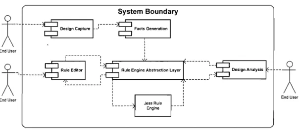
4.3.3.3 Anti-pattern Rules ... 51 4.3.3.4 Coalesce Rules ... 53 5 IMPLEMENTATION ... 54 5.1 IMPLEMENTATION ARCHITECTURE ... 54 5.1.1 Design Discovery ... 55 5.1.2 Facts Generation ... 61
5.1.3 Rule Engine Abstraction Layer ... 62
5.1.4 Quality heuristics Editor ... 63
5.1.5 00 Design Analysis ... 64 5.2 GU!. ... 65 5.3 IMPLEMENTATION ISSUES ... 72 6 EVALUATION ... 75 6.1 EVALUATION PROCEDURE ... 75 6.1.1 Example Selection ... 76 6.1.2 Non-example Selection ... 77 6.1.3 Evaluation Results ... 77 6.2 RESULTS ANALYSIS ... 82 6.2.1 Positive results ... 83 6.2.2 Negative results ... 85 6.2.2.1 Ambiguous Results ... 85 6.2.2.2 Failed Results ... 87 6.3 CASE STUDY ... 90
7.1 FUTURE WORK ... 96
7.2 CONCLUSION ... 96
REFERENCES ... 98
APPENDIX A PARTIAL ANTLR JAVA GRAMMAR ... 103
APPENDIX B - JESS RULE DTD ... 105
APPENDIX C JESS RULE XSLT ... 106 APPENDIX D - QUALITY HEURISTIC JESS RULES ... I08
List of Figures
Figure 1 Design Architecture ... ,. ... 6
Figure 2 Observer instance and corresponding fragment structure ... 13
Figure 3 Observer Design Pattern ... 22
Figure 4 Blob Anti-pattern ... ; ... 26
Figure 5 Beverage Class Diagram ... 27
Figure 6 Improved Beverage Class Diagran;t ... 30
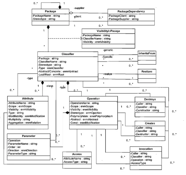
Figure 7 UML Meta-Model ... 37
Figure 8 Independent Rule Representation ... .40
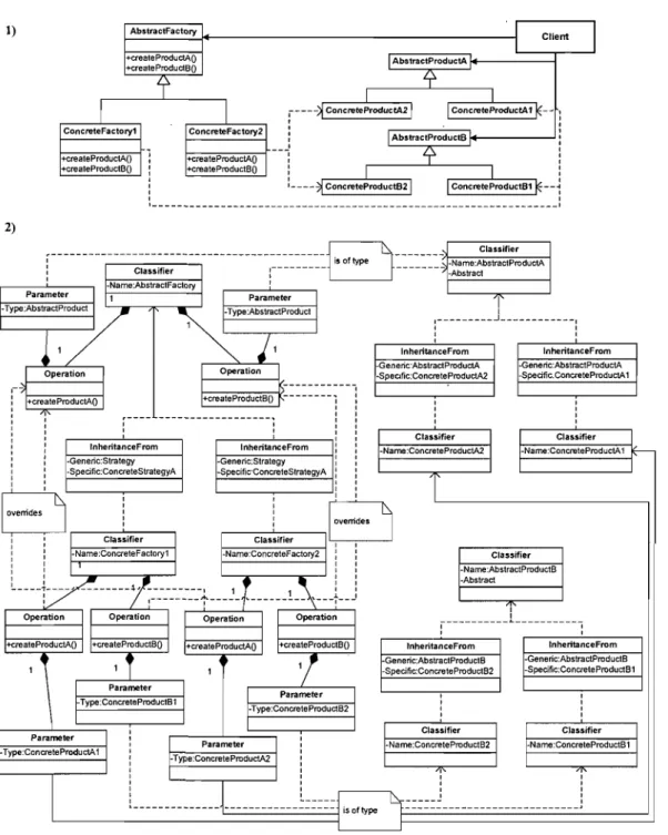
Figure 9 the design pattern Abstract Factor pictured as (1) a UML c1ass diagram and (2) as an independent pattern definition ... .41
Figure 10 Observer pattern in meta-modeL ... .43
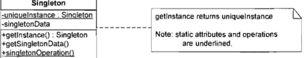
Figure Il the Singleton design pattern ... .43
Figure 12 Implementation architecture ... 54
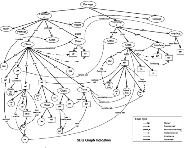
Figure 13 SDG Graph ... 58
Figure 14 Design Discovery Diagram ... 59
Figure 15 Main Window of the Prototype ... 65
Figure 16 Submenu of Design Recovery ... 65
Figure 17 the SDG Graph Viewer ... 66
Figure 18 the Submenu of F acts Generation ... 66
Figure 19 the Facts Viewer ... 67
Figure 20 Meta-model templates viewer.. ... 68
Figure 21 the submenu of Knowledge Base ... 68
Figure 22 Quality heuristics viewer window ... 69
Figure 23 Rule Editor Window ... 70
Figure 24 the submenu of Design Analysis ... 70
Figure 25 Analysis Configuration ... 71
Figure 26 Analysis Results ... 72
Figure 28 State Design Pattern ... 86
Figure 29 Bridge Design Pattern ... 87
Figure 30 Adapter irnplernentation variants ... 89
Figure 31 Anti Cornrnon-code Private Function ... 89
List of Tables Table 1 Quality Heuristics Detection Results ... 79
Table 2 Validation ofthe Detection Results ... 80
Table 3 Case Study Results ... 91
1 Introduction
The demand for quality software continues to intensify due to our society's increasing dependence on software systems and the often devastating effect that a software error can have in terms of life loss, financialloss or time delays. Today' s software systems must ensure consistent and error-free operation every time they are used. This demand for increased software quality has resulted in quality being more of a differentiator between products than it ever has been before. In a marketplace of highly competitive products, the importance of delivering quality is no longer an advantage but a necessary factor for companies to be successful.
1 .
1 Motivation
While there is uniform agreement that we need quality software, the question of how to measure and assure quality is far from a settled issue. Software metrics have been used to address this issue for several decades; many measures have been proposed in the literature to capture the structural quality of object-oriented code and design, e.g., [McCabe, 1976], [Fenton, 1991], [Chidamber and Kemerer, 1991], [Chidamber and Kemerer, 1994], [Li and Henry, 1999], and [Lorenz and Kidd, 1994]. These measures are being used to address not only different aspects of software quality such as maintainability, reliability, reusability and so forth, but also on the finer granularity of object-oriented properties such as cohesion, coupling and complexity. Once the necessary measurement instruments are in place, the assessment of even large software systems can be thus done very fast, at a low cost, with little human involvement. However, commercial software developers have made relatively little use of them. One of the main drawbacks of metrics is that results are provided in numeric value and are thus less intuitive than the guidelines derived from the practical experience of skilled developers for common software engineers to understand problems and how to locate and fix those problems. Another reason for this is that understanding and applying metrics can be very complicated and is generally only recommended to experienced developers. In addition, there is a lack of
association between the proposed metrics for evaluating the object-oriented design and the daily decisions made by developers.
Consequently, software developers are more inclined to rely on their intuition about the complexity of a system, rather than on sorne quantified metrics. The process of code or design review is accepted naturally by the majority of software engineers; many organizations execute design reviews by expert designers to improve the design of a large system and to avoid design flaws [Haynes, 1996].
For instance, once an object-oriented developer had completed a design regardless of the methodology used, the developer's main question was, "Now that l have my design, is it good, bad, or somewhere in between?" In asking an object-oriented guru, the developer was often told that a design is good when "it feels right." While this is of little use to the developer, there is a kemel of truth in such an answer. The guru runs through a subconscious list of heuristics, built up through his or her design experience, over the design. If the heuristics pass, then the design feels right, and if they do not pass, then the design does not feel right.
However, there are several concems about the process of evaluating a design by consulting the object-oriented gurus. First, expert designers are hard to find and expensive to use. Second, this process, the identification of good or problematic 00 software constructions, is very difficult to do manually for large systems. We can highlight the following reasons for this difficulty:
• Software systems that need to be reengineered are usually medium / large in
size, making manual search for problems unfeasible.
• Systems are developed by different developers or teams. Design problems can
be spread across several subsystems and thus cannot be detected locally.
• In most cases, the only reliable source for design information is the source
code. Models, when available, either are out of date or are too superficial to support a design analysis. However, the manual analysis of source code limits
the scope of the problems that can be found in a timely and economically way.
• Developers often do not know what kind of problems they should be 100 king
for when they have to evaluate their designs. A common knowledge-base containing potential design problems can provide a valuable support in this case.
• Expertise of gurus is generally designed to be used by human beings not for
automated CASE tools.
1.2 General Methodology
To address the aforementioned problems, the general methodology is to analyze the legacy code, specifying frequent design problems or reusable designs as queries and locating the occurrences of these problems or reusable designs in a model derived automatically from source code.
The first step in the methodology is to parse the source code and to produce high-level design information. Doing so leaves the concrete implementation behind and moves towards a higher level of abstraction at which specifications of those problems or reusable designs are given. To be able to express and interpret the information gathered from source code, a meta-model for object-oriented systems has to be set up. This meta-model defines the different entities and relations that may occur in the design of an object-oriented program. The model of a legacy system that conforms to the meta-model can be stored as a graph, as entities and relations, or as predicates. This makes it possible to query and manipulate the model using different query languages.
To detect problematic or reusable structures in the design of a system, the second step in the methodology is to search for certain patterns representing those problematic and reusable designs in the meta-model buiIt from the target system. This means that the methodology has to be able to specify problematic or reusable designs and to
query the model for the existence of a specified problematic or reusable design. The result of such a query is a piece of design specifying the location of the problematic . or reusable design in the system. Such a piece of design in the meta-model is often
referred to as a design fragment.
Several ways to specify queries on a design model exist in terms of the ways for representing the design model as aforementioned. A model can be understood as a typed graph, and the queries become algorithms working on this graph. A model can be specified by sets and relations. Queries then take the form of relational algebraic expressions. A model can also be expressed by logical propositions and be queried using predicate calculus, e.g., using alogie programming language.
1.3 Our Approach
The three above-mentioned approaches represent different viewpoints about the same meta-model. Although they are equivalently powerful in a sense and the corresponding models and queries can be converted into each other, each ofthem has its advantages and shortcomings in certain tasks.
For our specifie problem, we adopted the logic prograrnming language approach, expert systems in other words. The reason is that expertise in design problems and reusable designs expressed in our model is mostly captured in literature in the form of natural languages and is primarily designed to be used by human beings. Expert systems, rule-based computer programs that capture the knowledge of human experts in their own fields of expertise, were a perfect solution for this problem. Though many expert systems have several major practicallimitations such as a lack of causal
knowledge1 and a knowledge-acquisition bottleneck2 [Giarratano and Riley, 1998],
expert systems have been successful in dealing with real-word problems that conventional programming methodologies have been unable to solve, especially those
1 Causal knowledge describes the expert systems do not really have an understanding of the underlying
cause and effects in a system.
2 Knowledge-acquisition bottleneck describes the problem oftransferring human knowledge into an
dealing with uncertain or incomplete information. According to a rule-based system's definition, Rule-based systems, or often called expert systems, are "software systems (or subsystems) that simulate as closely as possible the output of a highly knowledgeable and experienced human functioning in a problem-solving mode within a specific problem domain" [Lane, 1986]. The three main components of an expert system are the knowledge base (i.e., the expertise in a specific domain), the inference engine (i.e., the controlling mechanism), and the user interface (e.g., explanation facilities). In general, the inference engine applies the rules in the knowledge base on the facts in working memory to construct an agenda. The list of rules that could potentially be fired is stored on the agenda. The execution engine fires the rules from the agenda, thereby changing the contents of the working memory and restarts the cycle.
Thus using predicates is easy to map the expertise and easy to simulate experts decision making. Our approach is to build a rule-based tool that detects good and bad 00 design constructions, i.e., constructions corresponding to standard solutions to recurring design problems (design patterns), or constructions that can result in future maintenance and reuse problems (design heuristics, anti patterns). Using this aid, it is possible to identify structures in a system that need to be modified to make it more flexible and reusable, and, by identifying existing design patterns, to facilitate the understanding system as a whole, including that of the badly documented systems.
Figure 1 shows the architecture of our approach. The whole process can be divided into the following steps:
• Expertise acquisition
• Design extraction
• Design facts generation
• Design analysis
The design-extraction process will parse source code and generate an intermediate representation of the source code - SDG (Semantic Directed Graph); then the design facts generation process will traverse SDG graph and produce facts representing
design information; those facts are then loaded into the working memory or saved into a repository to be used later on. These facts are stated in predicates corresponding to the constructions defined in the meta-model for object-oriented software. This definition of this model was based on the UML semantic meta-model [UML, 1997].
Rule Based Expert System---~---_
Source code Design Information Facts Generation Working M o r y - - - , Design Analysis Common Knowledge Knowledge Acquisition
Knowledge Base: uality Heuristi
Design heuristic and Design Pattern
Results
Figure 1 Design Architecture
Quality heuristics compose the knowledge base in ourapproach, which are confined from design heuristics, design patterns and anti-patterns (we name them as common
knowledge). The common knowledge, which shows what a good object-oriented system should look like, exists in the literature. Originally these guidelines were meant to be followed by a human developer when creating a new design, rather than by an automatic tool detecting violations of design rules in a given design of a legacy system. Quality heuristics are manually examined to see whether they could be used for automatically detecting problems in the CASE too1. Those proven quality heuristics are formalized into production rules and saved into the rule repository.
Finally the design analysis process will apply quality heuristics rules' to facts representing design information and will pro duce a report of violations and conformances found in the target system.
We have implemented a prototype tool according to our approach and have evaluated the prototype tool on several open-source systems. The results show that our approach can provide the following benefits to software engineers:
• Use the approach has been accepted and used naturally by software engineers.
• Define and formalize quality heuristics into the knowledge base.
• Show the location of a problem directly instead of showing a flood of metrics
values that require further interpretation.
• Illustrate what kind of problem it belongs to.
• Comprehend the source code.
• Define a rule engine abstraction layer that allows us to develop our rules in a
vendor-neutrallanguage.
• Give a promising solution to the problem.
1.4 Structure of the thesis
The thesis consists of 7 chapters as follows.
Chapter l, Introduction: talks about the motivation of our work and the general methodology; depicts architecture of our prototype; introduces main components in the prototype and finally shows the advantages of our approach.
Chapter 2, State of the Art: lists related work, discusses similarities and differences between their work and ours.
Chapter 3, Quality heuristics: presents the concepts and relationships of design heuristics, design patterns and anti-patterns; quality heuristic are refined from those raw sources.
Chapter 4, Quality heuristics formalization and identification: introduces
production systems; defines selected UML constructs in production terms; and formalizes and identifies design quality heuristics rules in the production system.
Chapter 5, Implementation: describes the design architecture of our prototype tool and its design details; illustrates the functionalities and GUI of our prototype tool; and discusses key implementation issues.
Chapter 6, Evaluation: presents an evaluation procedure and shows evaluation results on selected open-source projects that have applied our prototype too1. Finally, this chapter presents a case study of the different versions of an open-source project.
Chapter 7, Conclusion and Future work: gives additional ideas outside the scope of the present thesis for future work with CASE tool and pro vides a conclusion for the work presented.
2 State of the Art
This chapter discusses related work; at first it provides a literature survey of works surrounding reverse engineering and research into quality heuristics formalization and identification, and presents a more detailed comparison of the se with the work provided in this thesis.
2.1
Literature survey
Object-oriented methodology has dominated software development area for several decades. Along with this trend, a considerable number of methods have been
introduced to help software engineers design and develop 00 products such as
[Rumbaugh et al. 1991] and [Booch, 1994] etc. Along with these methods, several tools became available (e.g., [Rational Rose, 1997], [Together, 2006]). The emphasis
of these methods and tools has been on how to develop semantically correct 00
models regarding the constructions available in modeling languages such as UML [UML, 1997], for example.
However, a correct model does not necessarily mean that it is flexible and reusable.
The expertise of 00 gurus and related research have bridged the gap between correct
models and quality design, and have been captured in the literature on heuristics [Riel, 1996], [Martin, 2000], [Lieberherr, 1996] and design patterns [Gamma et al., 1995], etc. The heuristics coyer important topics ranging from classes and objects
with emphasis on their relationships to physical object-oriented design3. Heuristics
can highlight a problem in one facet of a design while design patterns can provide the solution.
Although design heuristics and design patterns were originally supposed to be used by hum an developers, works introduced in [Brown, 1996], [Grotehen and Dittrich, 1997], [Bar and Ciupke, 1998], [Prechelt and Kramer, 1998], [Correa et al., 2000]
3 Physical object-oriented design [Riel, 1996] involves the techniques used to map logical design
and [Wenzel, 2006] have demonstrated how to use them in an automatic manner, that is, how to integrate the expert's knowledge and thinking patterns into CASE tools. There are two main approaches to doing heuristics or pattern detection; one is by using graph matching, and the other way is by using production system.
2.2 Related work
Several works related to the reengineering of legacy object-oriented systems and the detection of design heuristics and design patterns have appeared in the last ten years. In this section, we compare them with our work in more detail.
2.2.1 MeTHOOD
MeTHOOD [Grotehen and Dittrich, 1997] is a framework that enables a design process that allows designers to review and improve object-oriented designs on the
meta-model level. It consists of a design-knowledge base (containing definitions of
measures, heuristics, and transformation rules) that works on a specification database
containing conceptual design schemas. It applies the heuristics rule on conceptual
design schemas to discover design flaws; it then uses transformation rules to create a proposaI for an alternative design. Measures are used to deal with conflicts when two or more heuristic rules (as weIl as transformation rules) are possible in a given context at the same time.
The overall design of MeTHOOD is that of an object-oriented database system. It
uses an object-query language to express a design knowledge base. The targeted design models are presented as records in the database. Moreover, it uses measures to overcome heuristic rules conflicts manually. MeTHOOD's design meta-model has to be entered by using a special editor and cannot be discovered from source code automatically. So far, only a few rules are given formaIly. In addition, MeTHOOD is more general in the sense that is provides concepts for transforming designs and for resolving problems. Comparing MeTHOOD with our approach, we use a production system to represent the design knowledge base and the targeted design models; a production system (expert system) is originally designed to capture the human
knowledge and to simulate human thinking ability; solving rule conflict is an integral part of a production system. Another difference is that our approach can read a model from source code and cornes with a set of formally defined rules that can be applied for problematic and reusable structures' detection.
2.2.2 GOOSE
GOOSE [Bar and Ciupke, 1998] is a reengineering tool set that helps the user to
detect design problems in a legacy source code. It formalizes design heuristic rules,
extracts design information from legacy source code and searches for violations of
these rules automatically. It mainly provides a set of design heuristic rules that can be
used in CASE tools automatically as weIl as those that not be. It uses the term
"testability" to judge how precisely these design heuristics can be used as an automated search for violations.
The differences between GOOSE and our prototype are that the goal of GOOSE is to detect design problems; the design heuristic rules are mainly retrieved from [Riel, 1996]; its implementation uses Prolog. Our prototype not only detects design
problems, but it also detects well-known good design structures to help end-us ers
comprehend the designs. Both detected structures will ultimately be used as inputs to evaluate overall software quality. Quality· heuristics are gathered from design heuristics, design patterns and anti-patterns, which are much broader than GOOSE. FinaIly, we use Jess [Jess, 2006] as our production system; it is reputed to be more efficient than the Prolog system.
2.2.3 KT
The first attempt to automatically detect design patterns was performed by Brown [Brown, 1996]. In this work, SmaIltalk code was reverse-engineered in order to detect four well-known patterns from the catalogue by [Gamma et al., 1995]. The algorithm was based on information retrieved from class hierarchies, association relationships
and aggregation relationships, as weIl as the messages exchanged between classes of the system.
The KT tool focused on searching for Composite, Decorator, Template Method and
the Chain of Responsibility. It noted that Strategy, State and Cornmand would
potentially be detectable, but that they would be ambiguous; so much so, that it would potentially be easy to obtain a false positive. Moreover, the KT tool is restricted to detecting design patterns in Smalltalk, since it regards only flows in VisualWorks for Smalltalk.
Our prototype is capable of detecting design patterns as weIl as design problems according to design heuristics and anti-patterns mIes. Our prototype can detect more design patterns than the KT tool does. Also our prototype is a mle-based system that uses UML meta-model-based predicates to uniformly express software design information as weIl as the knowledge of design patterns, anti-patterns and design heuristics. Our prototype shares the same shortcoming as does the KT tool, which is a false positive result for the detection of Strategy and State design patterns.
2.2.4 OMT
OMT [Florijn, 1997] supports working with design patterns when developing or maintaining object-oriented programs. This tool provides three integrated views of a program: the source code view, design view and occurrences of design patterns in the program. The tool assists developers using patterns in three ways:
• Generating program elements (e.g., classes, hierarchies) for a new instance of
a pattern, taken from an extensible collection of "template" patterns
• Integrating pattern occurrences with the rest of the pro gram by binding
program elements to a role in a pattern (e.g., indicating that an existing class plays a particular role in a pattern instance)
• Checking whether occurrences of patterns still meet the invariants governing
Subiecr' 10
Attach(Observer) observers ".., Observer 'i
DeJach(Ob,erver)
1 UpdaJeu' 1
NoJifyO
~
h
subOact
ConcrSubjecl • ObserverA' ObserverB'
GetstateO UpdateO' Update(),
sUbjectState
~ observerState observerState subleCI
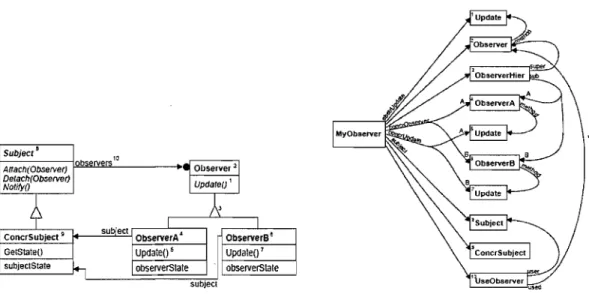
Figure 2 Observer instance and corresponding fragment structure
The tool proposed a mechanism for representing patterns as a set of fragments, called "The Fragment Model." This breaks down the pattern in terms of what it must provide: relationships with other classes (including inheritance), methods that must be present, and how they are connected with one another. Each one of these requirements is a fragment, and a collection of fragments together under one 'root' fragment defines a pattern. The aim of the fragment model is to provide a definition of the design patterns that can be used in a practical tool to allow the developer to instantiate patterns from scratch or from existing code. An example of a fragment is shown in Figure 2.
Our prototype is a rule-based system, it uses UML meta-model-based predicates to
express software design information instead of "The Fragment Model" in OMT. It
will detect design problems as weIl as well-known good design structures. OMT does not offer support for the automatic search of design patterns; it can generate source code when a user selects a pattern template and does refactorings, a suite of transformations that restructure and extend the program on a design level according to designated patterns.
SAD [Moha and Gueheneuc, 2006], proposes a language (Rule Card) and a framework (SAD) to express design defects synthetically and to generate detection algorithms automaticaIly.
Rule card specifies design defects syntheticaIly. Rule cards are expressed using a BNF grammar. A rule card is identified by the keyword RULE_CARD, followed by a name and a set of rules specifying this specific design defect as a set of code smells. A rule describes a code smell as a list ofproperties (metrics, structural, or semantics). The automated generation of detection algorithms relies on the SAD framework.
SAD provides the building blocks common to aIl detection algorithms. It includes the
PADL and SADDL meta-models, which represent object-oriented programs and provide constituents related to design defects to de scribe models of rule cards respectively.
FinaIly, SAD includes algorithms to visit models of rule cards and to generate detection algorithms from these models.
Our prototype is a rule-based system; it detects design problems as weIl as weIl-known good design structures. Their meta-model and our meta-model are quite similar. The rule card is interesting for us; we can use it in our knowledge-acquisition process to automatically generate quality heuristic rules from common knowledge.
3 Quality Heuristics
Designing object-oriented software is difficult; designing reusable object-oriented software is even more difficult. You must find pertinent objects, factor them into classes at the right granularity, define class interfaces and inheritance hierarchies, and establish key relationships among them. Your design should be specific to the problem at hand but also general enough to address future problems and requirements.
Experienced object-oriented designers do make good designs. Experienced design~rs
evidently know something that inexperienced designers do not. What is it that they know? One thing expert designers are aware of is a list of guidelines for good or bad designs based on their years of experience. These guidelines help them develop good design and improve design quality. These guidelines are called design heuristics. Experts also know not to solve every problem from first principles. Rather, they reuse solutions that have worked for them in the past. When they find a good solution, they use it again and again. Such experience is part of what makes them experts. Consequently, recurring patterns of classes and communicating objects are found in many object-oriented systems. These patterns solve specific design problems and make object-oriented designs more flexible, elegant, and ultimately reusable. Design pattern is the name of these reusable good solutions or recurring patterns. The knowledge of experts not only includes the patterns related to good design, but also the patterns related to design problems, such as reusable resistant structures, good patterns applied in wrong contexts, etc. Anti-pattern is the name of these bad solutions. Quality heuristics are developed from design heuristics, design patterns and anti-patterns, which are the core of our prototype. We discuss design heuristics first and, thereafter, we talk about design patterns and anti-patterns. At the end of this chapter, we explain relations among three ofthem.
3.1 Design Heuristics
Experienced 00 . developers can look at source code or UML diagrams directly and identify design heuristics that influence the system's design. They then exert judgement regarding the balance of these design heuristics to form an opinion about the quality of the component or system in question. This process is largely influenced by the opinions of individual developers and involves a number of aesthetic components.
Many publications have attempted to capture the expertise of skilled 00 developers, such as [Meyer, 1988], [Martin, 1996a], [Martin, 1996b], [Martin, 1996c], [Riel, 1996], and [Lieberherr, 1996], etc. As explained in [Meyer, 1988] and [Martin, 1996a]. F or instance, "Classes should be open for extension, but closed for modification." The goal of this design heuristic is to allow classes to be easily extended to incorporate new behaviour without modifying existing code. In other words, designs should be resilient to change and flexible enough to take on new
functionality to meet changing requirements. In addition, Riel, for example,
documented 61 golden mIes of OOP [Riel, 1996]. Every mIe links to a potential problem in the design where the mIe was violated. He describes them in the following way: "not hard and fast mIes that must be followed under penalty of heresy. Instead, they should be thought of as a series of waming bells that will ring when violated. The waming should be examined, and if warranted, a change should be enacted to remove the violation of the heuristic. It is perfectly valid to state that the heuristic does not apply in a given example for one reason or another." He classified aIl the heuristics into 8 categories: Classes and Objects, Topologies of Action-Oriented Versus Object-Oriented Applications, Relationships Between Classes and Objects, Inheritance Relationship, Multiple Inheritance, Association Relationship, Class-Specific Data and Behaviour and Physical Object-Oriented Design.
Another example is K. Beck and M. Fowler's collection of code smells [Fowler, 1999]. Code smells are used to help software developers identify problematic code
and to decide when this code needs to be improved by refactoring. The authors' choice ofthe term "smeIls" emphasises the vague and subjective nature of heuristics.
There are several possible types of relationships between heuristics. The most important two are implication and contradiction [Bar and Ciupke, 1998]. The term "implication" is used to mean that the conformance to one heuristic indicates the conformance to another. For example, Riel's Heuristic RH2.1 "AlI data should be hidden within its class" implies the Information Hiding Principle. This principle suggests that the details of an object that are most likely to change, or "do not contribute to its essential characteristics" [Booch, 1994], should be hidden.
Many contradicting heuristics are derived from differing opinions about good 00 design. For example RH5.7, "AlI base classes should be abstract" discourages concrete base classes; however satisfying this heuristic could result in a Lazy Class Smell. Other contradictions result from conflicting forces of design. The simple st example is RH5.4 and RH5.5, which state, "in theory, inheritance hierarchies should be deep - the deeper the better" and, "in practice, inheritance hierarchies should be no deeper than an average person can keep in his or her short-term memory. A popular value for this number is 6", respectively.
When faced with contradicting heuristics, the developer should examine the design further to determine whether or not both of them are applicable in their particular situation, and if they are, decide which one "plays the more important role" [Riel,
1996].
3.1.1 Human Factors
Heuristics are expressed in natural language, and, thus, the process of evaluating 00 designs with respect to these heuristics can be very subjective. Human factors, such as experience, role, and knowledge of the design in question, aIl contribute to an individual's interpretation. As Beck and Fowler put it: "in our experience, no set of metrics rivals informed human intuition" [Fowler, 1999]. From this, it is apparent that
automated heuristics cannot supplant the judgement processes of experienced developers, but instead, should be used to facilitate developers' work (novice or experienced).
3.1.2 Relation to Design Metrics
"A heuristic is not a metric" [Gibbon and Higgins, 1996]. Heuristics are rules and guidelines derived from the practical experience of skilled developers. They are expressed using natural language and conventionaHy have very vague, subjective definitions. Metrics, on the other hand, are very formaI and precisely defined measures of software. They are typicaHy, but not always, derived from sound conceptual and theoretical information.
It is common for metric results to be in the form of data values that can be displayed
using appropriate measurement scales. Examples of such scales include: nominal, ordinal, interval, and ratio. These results can be effectively used in identifying problem areas in code; however, once a problem has been detected, metrics fail to provide developers with the guidance required to resolve the problem.
3.2
Design Pattern
In order to avoid redesigning, or at least to minimize it, experienced object-oriented designers explain you that a reusable and flexible design is difficult if not impossible to get "right" the first time. 'Before a design is finished, they usuaHy try to reuse it several times, modifying it each time.
Meanwhile, new designers are overwhelmed by the options of design methodologies available; those designers who come from a procedure-oriented background tend to
faH back on non-object-oriented techniques they have used before. It takes a long
We all know the value of design experience. How many times has one had design déjà-vu-that feeling that one has solved a problem before but not knowing exactly where or how? If one could remember the details of the previous problem and how it was solved, then the experience could be reused. Design experience helps designers reuse successful designs by basing new designs on prior experience. A designer who is familiar with such patterns can apply them immediately to design problems without
having to rediscover them. An analogy helps illustrate the point. Novelists and
playwrights rarely design their plots from scratch. Instead, they follow patterns like "Tragically Flawed Hero" (Macbeth, Hamlet, etc.) or "The Romantic Novel" (countless romance novels). In the same way, object-oriented designers follow patterns like the pattern of "represent states with objects" and "decorate objects so you can easily addlremove features." Once you know the design pattern, many design decisions follow automatically.
Design patterns have been one of the most significant developments in software engineering in the past decade. The aim of this field is to identify and catalogue the knowledge and expertise that has been built up over many years of software engineering. Design patterns can be identified in aIl parts of the development process: architecture, analysis, design, coding, reengineering, as weIl as in specifie application areas such as real-time programming or in user-interface construction. Design patterns are in no way invented; they are discovered or "mined" from existing systems. The motivation is to uncover proven designs that experts have already used and reused and to distil from these the essence of the solution with domain-specifie detail removed. The resulting nugget of design wisdom can then be documented and made generally available. This pattern can be assimilated by other designers and applied in other domains.
The notion of a design pattern in software was borrowed from the work of the architect Christopher Alexander, who described the process of architecting living space (be it the corner of a room or an entire city) in terms of patterns. He defined the notion of a pattern in the following way:
Each pattern is a three-part rule, which expresses a relation between a certain context, a problem, and a solution.
Varying definitions of the term pattern abound, but this "three-part" version suits our CUITent purposes. Gabriel puts the Alexandrian definition into a software context in this way:
Each pattern is a three-part rule, which expresses a relation between a certain context, a certain system of forces which occurs repeatedly in that context, and a certain software configuration which allows these forces to resolve themselves [Gabriel, 1995].
In contrast to the design heuristic, the available design patterns today in the literature are described in explicit and organized form. In a general way, all descriptions of a design pattern must contain the following information:
• Pattern Name and Classification: Gives the pattern a name that becomes part of the designer's vocabulary and conveys the essence of the pattern succinctly.
• Intention: Explains what the design pattern does and what particular design problem it addresses to.
• Also Known As: Gives other names used for this pattern.
• Motivation: Illustrates the design problem and how the classes and object structures solve the problem.
• Applicability: Talks the design pattern can be applied in, in which situations, and how to recognize these situations.
• Structure: Presents a graphical representation of the participating classes in the pattern, using a graphie notation similar to OMT. It also describes the sequences of requests and collaborations among objects by means of interaction diagrams.
• Participants: Describes the classes and objects participating and their responsibilities.
• Collaborations: Describes how the participants collaborate to carry out their responsibilities.
• Consequences: Describes how the design pattern supports its objective and what aspects of the systems structure it lets vary independently. • Implementation: Explains what techniques should be taken into
consideration during the implementation period.
• Sam pie Code: Illustrates how to implement the pattern III C++ or SmaIltalk.
• Known Uses: Presents a short enumeration of the existing designs where the pattern has been used.
• Related Patterns: Shows what design patterns are closely related to this one, what their differences are, and which other patterns this pattern could be used with.
As the number of discovered design patterns grows, it make sense to partition them so that we can organize them, narrow our searches to a subset of aIl Design patterns, and make comparisons within a group of patterns. The most well-known scheme, which was used by the first pattern catalogue, partitions the patterns into three distinct categories based on their purposes [Gamma et al., 1995]:
• Creational patterns involve object instantiation and provide a way to decouple
a client from the objects it needs to instantiate, such as Singleton, Abstract Factory, Factory method, ...
• Behavioural patterns are concerned with how classes and objects interact and distribute responsibility, such as Visitor, Observer, State, Iterator, etc.
• Structural patterns allow for composing classes or objects into larger
structures, for example, Adapter, Composite, Decorator and Façade are in this category.
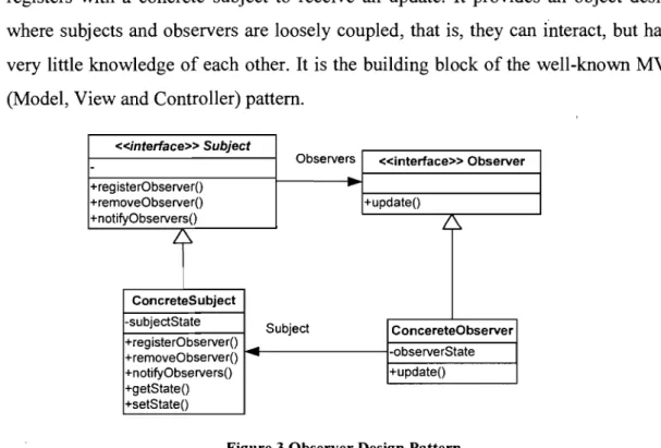
Design patterns in [Gamma et al., 1995] are more abstract and focus on problems in object-oriented software in general. For example, The Observer pattern de fines a one-to-many dependency between objects, so that when one object changes state, aIl of its dependents are notified and updated automatically. Its structure is shown in Figure 3. The clients use Subject interface to register observers and also to remove observers; observer interface has one method, updateO, that gets called up when the subject's state changes; a concrete subject always implements the Subject interface. Concrete
observers can be any c1ass that implements the Observer interface. Each observer
registers with a concrete subject to receive an update. It provides an object design
where subjects and observers are loosely coupled, that is, they can interact, but have
very little knowledge of each other. It is the building block of the well-known MVC
(Model, View and Controller) pattern. «interface» Subject
Observers «interface» Observer
-+registerObserverO
...
+removeObserverO +updateO +notifyObserversO ~1
ConcreteSubject -subjectState Subject ConcereteObserver +registerObserverO -observerState +removeObserverO +notifyObserversO +updateO +getStateO +setStateOFigure 3 Observer Design Pattern
The present thesis focuses on the automatic detecting of occurrences of design patterns as weIl as of the design problems. We choose to work with patterns at the design level for two reasons:
• It is a ri cher set than the program-Ianguage specific patterns found at the
co ding level.
• They are more concrete than those found at the analysis level, so that
detecting the occurrences of these design-Ievel patterns automatically from source code is realistic.
The notions of formalization and automation are not generally welcomed in the patterns community. James Coplien expressed this distaste c1early in [Coplien, 1996]: "Patterns are not designed to be executed or analyzed by computers, as one might imagine to be true for rules: patterns are to be executed by architects with insight, taste, experience, and a sense of aesthetics." We have to agree his c1aim in terms of
the first two p~s of Gabriel's definition. How it is decided that a context is
appropriate for the application of a pattern and that assess the forces acting in this context will be resolved by the pattern is a matter of "insight, taste, experience, and a
sense of aesthetics." However, the third part of the pattern definition, that of applying the software configuration that resolves the forces, is c1early a potential candidate for automation.
In Chapter 4, we will present amethodology for the development of automated design pattern transformations where the designer defines the context to which the pattern is to be applied and the actual application of the software structure is automated. Other work in the area of automated pattern application is considered in that chapter as well. Thus in this chapter we focus on other uses of formalization and automation in the context of design patterns.
Since software systems are progressively becoming larger and more complex, the task of understanding while developing and especially while maintaining software is becoming more and more difficult. Therefore, the use of patterns has become a helpful methodology to develop software in a more structured and understandable way. A key reason for using a pattern is that it helps describe the system, as weIl as implement it. Thus, when a pattern is used (and documented) in a code base, it aids other developers looking to extend the system.
3.3
Anti-Pattern
A design pattern gives a general solution to a recurring problem in a particular context; the universe just would not be complete if we only had positive parts and no negative part. The complementary part is anti-pattern, which tells you how to go from a problem to a BAD solution. Brown et al. give the expression "anti.-pattern" the formaI definition of "a literary form that describes a commonly occurring solution a problem that generates decidedly negative consequences. An anti-pattern describes a general form, the primary causes which led to the general form; symptoms of the general form; and a refactored solution describing how to change the Anti-pattern into a healthier situation" [Brown et al., 1998].
The concept of anti-pattern was first formally introduced from "Antipattern Session Notes" presented in the Object World West conference in 1996 by Michael Akroyd.
The discussion of the usefulness of anti-patterns began almost in parallel with the introduction of patterns. Similar work on providing software guidance based on dysfunctional behaviour and refactoring a solution has been documented by B. Webster [Webster 95], and J. Coplien [Coplien, 1996] and [Brown et al., 1998].
Like design patterns, there are many types of anti-patterns:
• Development anti-patterns that comprise technical problems and solutions that
are encountered by programmers.
• Architectural anti-patterns that identify and resolve common problems in how
systems are structured.
• Managerial anti-patterns that address common problems in software processes
and development organizations.
As we are concentrating on automated design knowledge identification, we will focus only on developing anti-patterns. The number of catalogued anti-patterns is still small, if compared with the amount of available design patterns in the literature. [Koenig, 1995] claims that it is more difficult to classify anti-patterns than their counterparts because people are more likely to expose their successes than their failures.
Analog to design patterns, anti-patterns are also described in a standardized structure. This structure is a little different from the structure of the design patterns due to the nature of the anti-pattern. Instead of a problem and a solution, an anti-pattern possesses two solutions: the first one generates negative consequences, whereas the second is a migration or refactoring of the first one, aiming to eliminate or at least to reduce its negative impacts.
[Brown et al., 1998] considers a structure for the description of anti-patterns, composed of the following sections:
• Name: analogous to the form of the design patterns. The philosophy of giving
facilitates the communication arnong the members of development tearns. An
anti-pattern can also be known by other narnes (synonymous).
• General form: this section identifies the main characteristics of the
anti-pattern, being able to include diagrams. The refactored solution resolves the problem described in this section.
• Symptoms and consequences: this section lists symptoms and resultant
consequences of this anti-pattern. The symptoms supply indications of where the anti-pattern can be detected. The consequences mention the problems if this bad solution is applied to a real problem.
• Typical causes: they identify the main reasons that lead to the appearance of
this type of solution.
• Known exceptions: anti-pattern behaviour and procèsses are not always
wrong; often there are specific occasions when this is the case.
• Refactored solution: this section explains a refactored solution that resolves
the forces in the anti-pattern identified in the "General form" section. The new solution is structured in terms of solution steps.
• Variations: this section lists the possible major variations of this anti-pattern.
If there are alternative solutions, they are described here as well.
• Related solutions: any closely-related anti-patterns are listed and the
differences are explained.
By documenting anti-patterns, we help others to recognize bad solutions before they implement them.
Figure 4 provides an example of anti-patterns named Blob, which is listed in [Brown
et al., 1998]. It is presented in the form described above as shown in Figure 4.
Name: The Blob
Also Known As: The God Class
General Form: The key problem is that the majority of the responsibilities are aUocated to a single class. One class monopolizes the processing; other classes primarily encapsulate data. The Blob is a procedural design even though it may be represented using object notations and implemented in object-oriented languages. That is why this anti-pattem frequently is found in designs or implementations made by former C programmers. The B10b is also frequently a result of iterative development where proof-of-concept code evolves over time into a prototype, and, eventually, a
production system. This is often caused by GUI-centric programming languages, such as Visual Basic. This kind of language is often used for rapid prototyping. The Blob is often accompanied by unnecessary code, making it hard to differentiate between the useful functionality of the Blob Class and no-Ionger-used code.
Symptoms and Consequences:
• Single class with a large number of attributes, operations, or both. A class with 60 or more attributes and operations usually indicates the presence of The Blob.
• A single controller class with associated simple, data-object classes. • The Blob Class is typically too complex for reuse and testing. Typical Causes:
• Lack of an object-oriented architecture. The designers may not have an adequate understanding of object-oriented principles or the team may lack appropriate abstraction skills.
• Lack of any architecture. The absence of definition of the system components, their interactions, and the specific use of the selected programming languages. The programming languages are not intended for use in this kind of task.
• Too limited intervention. In iterative projects, developers tend to add Iittle pieces of functionality to existing working classes, rather than add new classes, or revise the class hierarchy for more effective allocation of responsibilities.
Known Exceptions: The Blob AntiPattem is acceptable when wrapping a legacy system. A final layer of code makes the legacy system more accessible.
Refadored Solution: A refactored solution means that we must fmd a way to rebuild our program. We must move behavior away from the Blob c1ass in a way that makes the Blob less complex and it is supporting classes more capable. The method for refactoring responsibilities is described below. 1. IdentifY or categorize related attributes and operations according to contracts. For example: everything in The Blob Class that deals with sorting (Sort_Catalog, Search_Catalog) is grouped together. So is everything that deals with printing, etc.
2. Now we look for "natural homes" for these contract-based collections and migrate them there. In this example, we can move everything that in volves sorting operations on a catalog to the Catalog Class. We do the same thing with the other groups of operations that can be migrated.
3. The third step is to remove ail "far-coupled", or redundant, indirect associations.
4. Next, where appropriate, we migrate associates to derived classes to a common base class.
5. Finally, we remove ail transient associations, replacing them as appropriate with type specifiers to attributes and operations arguments.
Variations: Sometimes too much hard work is done to refactor The Blob Class. There is another way to do it, but it provides an "80%" solution. Instead of a bottom-up refactoring of the entire class hierarchy, it may be possible to reduce the Blob cIass from a controller to a coordinator.
Figure 4 Blob Anti-pattern
Knowing the Blob anti-pattem, you can get the following benefits:
• An anti-pattem tells you why a bad solution is attractive: no one would
choose a bad solution if there was not something attracting people. One of the biggest jobs of the anti-pattem is to let you be aware of the attractive aspect of the solution.
• An anti-pattern tells you why, in the long term, that solution is bad: in order to understand why it is an anti-pattern, you must understand how it is going to have negative effects down the road. The anti-pattern describes where you will get into trouble by using the solution.
• An anti-pattern suggests other applicable patterns that may provide good
solutions: to be truly helpful an anti-pattern needs to point in the right direction; it should suggest other possibilities that may lead to good solutions. Anti-patterns can be seen as an extension of patterns, since they represent traps and pitfalls concerning the patterns. They can also be seen as a learning tool that helps people to learn from other people's mistakes and to recognize early on where one starts to go wrong.
3.4 Relation between Design Heuristic, Pattern and Anti-Pattern
As Riel said, "Design heuristics can highlight a problem in one facet of a design while design patterns can provide the solution" [Riel, 1996]. Anti-patterns are complementary to design patterns; moreover, design heuristics and design patterns are the sources of new anti-patterns.
Beverage -description -milk -soy -mocha -whip +getDescriptionO +costO +hasMilkO +setMilk() +hasSoy() +setSoyO +hasMochaO +setMochaO +hasWhipO +setWhipO
~
HouseBlend DarkRoast Decaf Espresso
+cost() +costO +costO +cost()
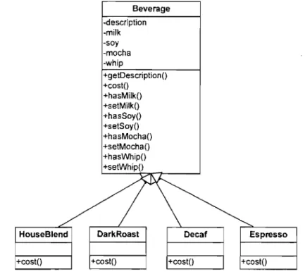
We use an example, a beverage ordering system, to show how this relationship works. In addition to ordering different types of coffee such as HouseBlend, DarkRoast, Decaf, and Espresso, etc., consumers can also ask for several condiments like steamed milk, soy, and mocha (otherwise known as chocolate), and have it aU topped off with whipped milk. As depicted in Figure 5, the Beverage class diagram has a beverage base class with instance variables to represent whether or not each beverage has milk, soy milk, mocha and whip. Different kinds of beverages are created by inheriting from base beverage class. The costO function in Beverage can calculate the costs associated with the condiments for a particular beverage instance. Subclasses will override costO, but they will also invoke the super version so that they can ca1culate the total cost of the basic beverage plus the costs of the added condiments. Using this design, the system seems to pro duce different coffees with different topping without any problem.
Before we examine the design further, we are going to introduce two fundamental design heuristics:
• Open-Closed Principle: Classes should be open for extension, but closed for
modification.
• Prefer Composition to Inheritance: favour object composition over class
inheritance on reuse.
"Open" means that one should feel free to extend the classes with any new desired behaviour. If needs or requirements change (and they will), just go ahead and make your own extensions. "Close" tells that we spent a lot of time getting this code correct
and bug free, so we can not let you alter the existing code. It must remain closed to
modification. The goal is to allow classes to be easily extended to incorporate new behaviour without modifying existing code. Designs that comply with this heuristic are resilient to change and flexible enough to take on new functionality to meet changing requirements. Even "open-close" heuristic sounds very contradictory. As it turns out, though, many of the design patterns give us time-tested designs that protect source code from being modified by supplying a means of extension. Thinking about the Observer pattern whose class diagram is shown in Figure 3, we can extend the
Subject by adding new Observers at any time, without adding code to the Subject. There are quite a few more ways of extending behaviour with other 00 design techniques.
The rationality of the second heuristic is that when inheriting behaviour by
subclassing, that behaviour is set statically at compile time. In addition, aIl subclasses
must inherit the same behaviour. If, however, we extend an object's behaviour through composition, then we can change the object's behaviour dynamically at runtime. By dynamically composing objects, we can add new functionality by writing
new code rather than by altering existing code. In other word, because we are not
changing existing code, the chances of introducing bugs or causing unintended side effects in pre-existing code are reduced.
Bearing the aforementioned two heuristics in mind, if we think about how the design might need to change in the future, we will find 'some potential problems deriving from the design of the beverage ordering system:
1. Price change for conçliments will force us to alter the base class code.
2. New condiments will force us to add new methods and alter the cost method in the base class.
3. We may have new beverages. For sorne of these beverages (iced tea?), the condiments may not be appropriate, yet the Tea subclass will still inherit methods like hasWhipO.
4. What if a customer wants a double mocha?
We have se en that representing our beverage plus condiment pricing scheme with inheritance has not worked out very weIl - we get rigid designs because it violates the "open-close" heuristic, or we add functionality to the base class that is not appropriate for sorne of the subclasses. That is why we "prefer composition to inheritance".
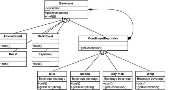
To follow the Open-Closed principle and the Composition-over-Inheritance" principle, we will apply the Decorator design pattern in the design of the beverage ordering system. We will start with a beverage and "decorate" it with the condiments