HAL Id: hal-00664877
https://hal.archives-ouvertes.fr/hal-00664877
Submitted on 31 Jan 2012
HAL is a multi-disciplinary open access
archive for the deposit and dissemination of
sci-entific research documents, whether they are
pub-lished or not. The documents may come from
teaching and research institutions in France or
abroad, or from public or private research centers.
L’archive ouverte pluridisciplinaire HAL, est
destinée au dépôt et à la diffusion de documents
scientifiques de niveau recherche, publiés ou non,
émanant des établissements d’enseignement et de
recherche français ou étrangers, des laboratoires
publics ou privés.
Adapting OCL Constraints After a Refactoring of their
Model Using an MDE Process
Kahina Hassam, Salah Sadou, Régis Fleurquin
To cite this version:
Kahina Hassam, Salah Sadou, Régis Fleurquin. Adapting OCL Constraints After a Refactoring of
their Model Using an MDE Process. 9th edition of the BElgian-NEtherlands software eVOLution
seminar (BENEVOL 2010), Dec 2010, Lille, France. pp.16-27. �hal-00664877�
Adapting OCL Constraints After a Refactoring of their Model Using an MDE
Process
Kahina Hassama, Salah Sadoua, Vincent Le Gloahecb, Régis Fleurquina
aSouth of Brittany University, Vannes, France bAlkante SAS, Cesson-Sévigné, France
Abstract
Refactoring is a kind of endogenous model transformation. Its aim is to restructure applications without changing their external behavior. Several studies have been carried out on the refactoring of UML models specifically on the refactoring of UML class diagram models. During refactoring, the OCL constraints associated with these UML class diagram models are omitted or manually rewritten, which often leads the system to an inconsistent state. We propose an approach to transform, as automatically as possible, these OCL constraints using the transformation model. This approach uses the used transformation model to find a sequence of basic refactoring operations that once applied to the initial model leads to the final model. Thus, we can use an already known results for OCL constraint transformations in case of stepwise model refactoring.
Keywords: UML models, OCL constraints, refactoring, model transformation
1. Introduction
Refactoring is an important activity within the domain of software maintenance [1, 2]. It is an essential activity for handling software evolution [3]. Refactoring is defined as change to the internal structure of software to improve certain software quality characteristics (such as understandability, modifiability, reusability, modularity, adaptability) without changing its observable behavior [4]. In the domain of Model Driven Engineering (MDE), refactoring is considered as a type of endogenous model transformation [5]. Indeed, the modification of a source model is done by model transformation to produce a target model so that both models conform to the same metamodel. Several studies have already been carried out on the refactoring of models, in particular in UML [6] models and especially on the refactoring of UML class diagram models [7, 8]. Beyond the capabilities of UML graphical diagrams to elaborate UML models, constraints are added to allow for the precision needed to write executable models [9]. These constraints are described using the Object Constraint language(OCL) [10]. Current UML model refactoring, especially UML class diagram refactoring, concentrate on the diagrammatic part, but the OCL constraints are neglected and become incoherent with the new model [11]. The solution used thus far is to modify them manually, which is very time consuming and error prone [12].
We propose an approach to transform, as automatically as possible, the OCL constraint invariants associated with UML models. For this, we use the transformation model that was used to transform the UML model to which the constraints are associated. Our approach is independent from any model transformation language, because it considers the transformation model as a “Black Box”. The main aim of our approach is to deduce the list of basic refactoring operations corresponding to changes made by this “Black Box” on a given model. This list allows us to use the tool proposed in [11] for the transformation of OCL constraints after each basic refactoring operation (stepwise approach). The remainder of the paper is organized as follows: the next section gives details of our approach. In Section 3, we show how to build the mapping table between elements of the initial model and those from the transformed one.
Email addresses:[email protected] (Kahina Hassam), [email protected] (Salah Sadou), [email protected] (Vincent Le Gloahec), [email protected] (Régis Fleurquin)
UML/OCL Meta-Model Source UML Model Target UML Model Annotated Target UML Model Annotated Source UML Model conform Source OCL Constraints Target OCL Contraints Order Mapping Table
Set of Basic Refactoring operations
?
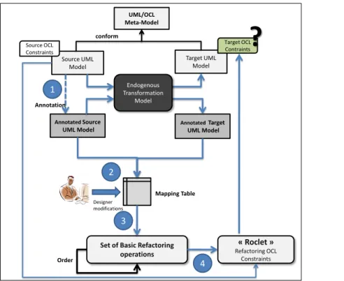
Annotation 1 3 2 4 « Roclet » Refactoring OCL Constraints Endogenous Transformation Model Designer modificationsFigure 1: The Global Approach
Section 4 concerns the extraction of the list of basic refactoring operations from the mapping table. A case study with the implementation of our approach is presented in Section 5. And finally, before concluding in Section 7, we give an overview of related work in Section 6.
2. Used Approach
For OCL constraints refactoring, we propose the approach described in Figure 1. The most important task in this approach is the representation of the transformation model as an ordered set of basic refactoring operations. When the ordered set is applied to the source model, then it leads to the same target model obtained through model transfor-mation.
We consider the transformation model as a “Black Box”, thus our approach is independent from a particular transfor-mation language. The sequence found does not represent the transfortransfor-mation model in its entirety. It represents only the processing performed by the transformation model on the source model. The refactoring operations considered in this work are those defined in [11] (Extract Class, Move Attribute, etc.)
To obtain the sequence of basic refactoring operations, we define three principal steps. The first step, as shown in Figure 1, annotates the source model by adding tags to each element from the source model. The aim of this step is to trace the source model elements. Then, we execute the model transformation to obtain an annotated target model. Using the source and target annotated models, we build a mapping table (Step 2 in Figure 1). The mapping table summarizes for each element from the source model its corresponding element(s) from the target model, if it still exists.
The third step uses the obtained mapping table to compute the sequence of basic refactoring operations. Once the sequence of basic refactoring operations is recovered and ordered, we use the approach presented in [11] for OCL constraints refactoring (Step 4). In [11], the authors describe for each UML refactoring operation its impact on the OCL constraint invariant associated with UML class diagram source model. The authors also identify which basic
operations have an impact or not on the OCL constraints. Their approach was implemented as an Eclipse plugin named Roclet [13]. Thus, by providing the obtained sequence of operations (Step 3) to Roclet, we transform the OCL constraints of the source model into constraints that conform to the target model.
The two following sections describe, respectively, Steps 1, 2 and 3. Step 4 is just a use of Roclet and will not be presented in this paper. For more information on using Roclet, the reader may refer to [13].
3. Tracking Model Elements
Traceability is very important during the model life cycle [14]. In the context of MDE (Model-Driven Engineer-ing), several definitions were proposed for traceability [15, 16, 17]. According to [16], traceability can be defined as: The ability to describe and follow the life of a requirement, in both a forwards and backwards direction (i.e., from its origins, through its development and specification, to its subsequent deployment and use, and through periods of on-going refinement and iteration in any of these phases).
In MDE, traces are generated through the process of model transformation as it is specified in the QVT (Query|View| Transformation)standard [18]. Many transformation languages like ATL [19] and Kermeta [20] include the definition of a traceability metamodel. But traceability models are often omitted when writing the transformation model. More-over, there are different techniques to calculate differences between models. Some are based on the use of a persistent identifier [21], while others use approximation approaches [22, 23].
In the context of refactoring, where operations are primarily used to manipulate existing elements, the existence of a persistent identifier (defined in the metamodel) for each element of the model seems indispensable to us. This makes the technique of comparing models, based on identifiers, the most appropriate solution. However, if we add an identifier to each element from the initial model and then we apply the transformation model (as a black box), there is no guarantee of finding these identifiers in the resulting model. Indeed, the current transformation languages use internal representations for each model without, necessarily, taking into account identifiers. The problem can be solved by adding identifiers in metamodels and forbid their modification by transformation models.
Unfortunately, metamodels do not define identifiers. For these metamodels, we propose an annotation mechanism, which plays the role of an identifier, allowing the traceability of elements after execution of the transformation.
3.1. Source Model Annotation
The annotation mechanism aims at maintaining a traceability link between the source and target elements. The annotation algorithm adds a tag to each model’s element. Thus, each element’s name in the model should conform to the following BNF syntax:
NameElement::= {Mark}{Name}{Mark}{Container}{Mark}{MetaClass}{Mark}{Type}{Mark} Mark::= [#xB-#xC] | [#xE-#x1F] | [#x7F-#x84] | [#x86-#x9F]
Name::=String Container::= String
MetaClass::= Package | Class | Attribute | Operation Type::= String | Integer | Boolean | Class
Mark: describes the string used to separate the different information. The choice of the mark is left to the designer who has a minimal knowledge of the transformation language;
Container: describes the name of the direct parent of each element in the model (e.g., if the element is an attribute then its container corresponds to the name of the class to which it belongs);
Name: describes the current element’s name;
MetaClass: describes the meta class of the current element (e.g., Package, Class, Attribute, etc.); Type: describes the type of the current element.
3.2. Building the Mapping Table
To be productive, traces need an adequate representation and/or visualization. In the literature, several representa-tions (matrices, cross-references, or graph-based representarepresenta-tions) can be found [24].
To keep the traceability link between source elements and target ones, we represent the traces in a mapping table. The traces will be used to deduce the basic refactoring operations that will enable us subsequently to transform OCL con-straints. This mapping table is a two dimension matrix (Source Elements, Target Elements). It is intended to simplify the visualization and representation of the various changes made in the model.
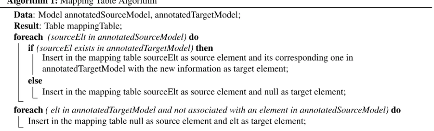
Algorithm 1: Mapping Table Algorithm
Data: Model annotatedSourceModel, annotatedTargetModel; Result: Table mappingTable;
foreach (sourceElt in annotatedSourceModel) do if (sourceEl exists in annotatedTargetModel) then
Insert in the mapping table sourceElt as source element and its corresponding one in annotatedTargetModel with the new information as target element;
else
Insert in the mapping table sourceElt as source element and null as target element;
foreach ( elt in annotatedTargetModel and not associated with an element in annotatedSourceModel) do Insert in the mapping table null as source element and elt as target element;
To build a mapping table, we propose Algorithm 1, which analyzes the annotated source model to retrieve information about its elements. Then, for each element, it analyzes the annotated target model to find one or more elements so that their information matches. If so, it then verifies their current information in the target model: if they are unchanged they will be inserted as is in the mapping table, otherwise it modifies them with new information before insertion. If no element corresponds to the source element, then the target element is marked as Null, which means that the element was either renamed or removed. This case will be handled in collaboration with the designer once the first version of the table is made by the algorithm (see bellow). If there are elements in the target model without corresponding ones in the source model (marked as Null), it means that the transformation has either created or renamed elements.
The mapping table produced by this algorithm is then proposed to the designer to take a decision about null values in targeted element. In case of rename, we have to check that the new name is considered by our algorithm as a new element. Then we associate these elements in the table. This processing corresponds to the collaborative step of our approach. Indeed, without help from designer, it is impossible to decide if the situation corresponds to a rename or a suppression .
Figure 2: Example of a mapping table
An example of a produced mapping table is given in Figure 2. The description of this mapping table is given below:
• (line 1) class Department is still contained in the same package; • (line 2) name attribute has moved from class Department to class Party; • (line 3) creation of a new association end (employeeEND) in the class Category; • (line 4) creation of a new class (Party) in the package (Package1);
• (line 5) creation of a new class (Category) in the package (Package1);
• (line 6) creation of a new association end (categoryEnd) in the class Employee; • (line 7) getName() operation has moved from class Department to class Party; • (line 8) creation of a new attribute (nameCategory) in the class Category;
• (line 9 and 10) The null value at the targeted model part means that the designer has to decide (delete or rename); • (line 11) possible creation of a new association end between class BankAccount and class Employee.
The designer’s decision may be: line 9 corresponds to a deletion, while line 10 corresponds to a renaming. To specify the new name, it will be suggested to the designer all the elements of the table that have the same metaclass than the renamed element and that have null as value in the initial model (supposed created). Thus, after the adjustments made by the designer, line 9 remains as it is, while lines 10 and 11 will be unified to signify the renaming.
4. Extracting the Basic UML Refactoring Operations
After the approval of the mapping table by the designer, we compute the set of refactoring operations (third step in Figure 1). These operations allow us to transform the OCL constraint invariants attached to the UML class diagram source model, according to the approach proposed in [11]. Algorithms used to deduce the different refactoring operations and the rules defined to ordain them are discussed below.
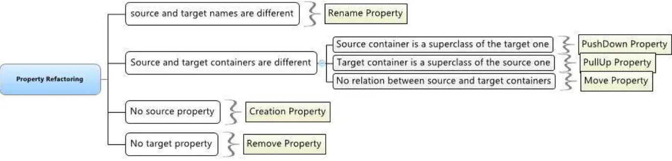
Figure 3: Property Refactoring Operations
4.1. Property Refactoring Operations
By property, we mean attribute, operation, and association end. Since the computing of basic refactoring opera-tions is the same for all properties, we show only one algorithm that is synthesized in Figure 3.
There are four types of operations that deal with properties, they are defined as follows:
• The PullUp Property operation moves a property from a subclass to a superclass [4]. • The PushDown Property operation moves a property from a superclass to a subclass [4].
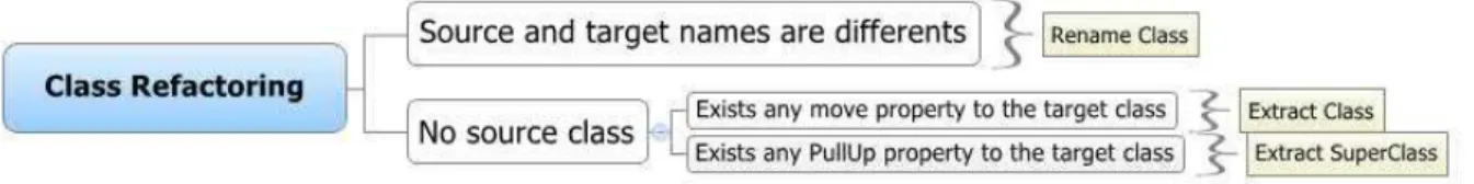
Figure 4: Class Refactoring Operations
• The Move Property operation moves a property from a source class to target class through an association [4]. • The Rename Property operation renames a property without changing its container [4].
If the containers of both elements differ (in this case, a container is a class), then the relationship between those two containers is tested. If the source element’s container is a superclass of the target element’s container, one can deduce that a “PushDown Property” refactoring has occurred. If it is the target element’s container which is a superclass of the source element’s container, then one can deduce that a “PullUp Property” has been performed.
However, if the source element does not exist, this implies that the target element has been created by the trans-formation. Finally, if the target element does not exist, then we can deduce that the element has been removed by the transformation. The creation or removal of properties are not considered refactoring operations. They are considered atomic operations that contribute to refactoring operations, such as “Extract Class”.
4.2. Extract Class and Extract Superclass Refactoring Operations
According to [4], the Extract Class operation creates a new class and moves the relevant features from the old class into the new extracted one and connects it with the old class with a new association such as the multiplicity is 1 on both sides. The Extract Superclass operation creates a superclass from two classes with similar features and moves the common features to the superclass.
Rename Classis a refactoring operation [11] that consists in changing the class’s name. To deduce if a model transformation has performed operations on classes, we have defined an algorithm, whose functioning is synthesized in Figure 4.
The algorithm scans the mapping table, and for each source element whose metaclass is “Class”, its name is compared to the target element’s name. If the latter has changed, then we can deduce that a “Rename Class” refactoring operation has been performed.
If a source element does not exist, this means that a new class has been created. In the context of UML models refactoring, a creation can be spawned by refactoring operations such as “Extract Class“ or ”Extract SuperClass“. To distinguish which one of these refactoring operations has been performed, we rely on the operations realized on properties. If a ”Move Property“ refactoring has been performed from the source class towards the target class, then we can deduce that the refactoring is of kind ”Extract Class“. On the contrary, if a ”PullUp Property“ operation has been performed from a source class towards a target class, this implies a refactoring of kind ”Extract SuperClass“. Those two kind of refactoring operating on class’s properties cannot co-exist. If such a case occurs, this implies inconsistencies during model transformation.
4.3. Ordering the Basic Refactoring Operations
The application of the previous algorithms returns a set of refactoring operations, in an undetermined order. Nev-ertheless, as the Roclet tool is used to perform the actual refactoring (of both the model and its constraints), these operations must be executed in a particular order so that the refactoring is properly applied. It is easily understand-able, for example, that it is impossible to move an attribute in a class if this class has not yet been created. Besides, if the operations are not well ordered, the model obtained after applying the refactoring operations will not be necessary the same as the target model that results from the initial “Black Box” transformation. Therefore, the transformed OCL constraints will not conform to the target model.
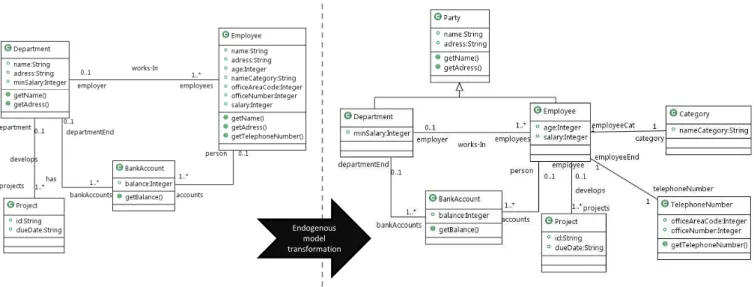
Endogenous model transformation
Figure 5: Endogenous Model Transformation
• Apply the operations that concern the container before the content, and so, deal with classes before properties (attribute, operation and association ends). Indeed, as stated in the OCL metamodel [10], a constraint requires a class as a valid context.
• Do not extract a class or a superclass from a class that has not yet been created. For example, given these two operations:
1. ExtractClass(class2:Class, class3:Class, role1:String, role2:String); 2. ExtractSuperClass(class1:Class, class2:Class, newName:String);
One must apply the operation (2) before applying (1), because when executing the first operation, the class class2does not yet exist.
• Do not make operations that concern properties (Move, PullUp or PushDown) on a class that has not yet been created. For example, if we have these two operations:
1. MoveProperty(a:Property, class1:Class, class2:Class, ae: Association End); 2. ExtractClass(class1:Class, class2:Class, role1:String, role2:String);
One must apply the operation (2) before applying (1), because, when executing the first operation, the class class2and the association end ae do not yet exist.
5. Illustrative Example
Figure 5 describes an example of an endogenous model transformation, the aim of which is the refactoring of a UML model. The UML class diagram source model (left part of Figure 5) specifies information about the depart-ments, their projects, their employees and bank accounts that are associated with both departments and employees. Eight OCL constraints are attached to this model. The first one is the (MinSalary) constraint, it ensures that in the de-partment no employee has a salary lower than the minSalary. The others ensure that the office number is different from the area code (OfficeNumbDIFFoffAreaCode), that all projects have at least two project managers (AtLeastTwoPro-jectManagers), that the project id is unique (UniqueId), that an employee is not associated to more than two projects
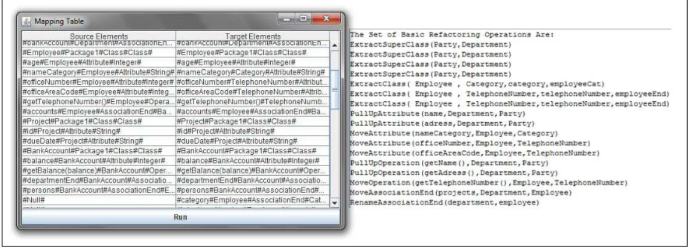
Figure 6: Mapping Table and the Set of Refactoring Operations
(MaxTwoProject), that the balance of any account associated to an employee is positive (BalancePositif), that in the de-partment there is a manager (DepartManager), that the employee name category is not empty. These OCL constraints are described below:
c o n t e x t D e p a r t m e n t i n v M i n S a l a r y : s e l f . e m p l o y e e s −> s e l e c t ( e | e . s a l a r y <= s e l f . m i n S a l a r y )−> s i z e ( ) = 0 c o n t e x t Employee i n v O f f i c e N u m b D I F F o f f A r e a C o d e : s e l f . o f f i c e N u m b e r <> s e l f . o f f i c e A r e a C o d e c o n t e x t P r o j e c t i n v A t L e a s t T w o P r o j e c t M a n a g e r s : s e l f . d e p a r t m e n t −> f o r A l l ( d | d . employees −> s e l e c t ( e | e . n a m e C a t e g o r y= ’PM’ )−> s i z e () > =2 ) c o n t e x t D e p a r t m e n t i n v U n i q u e I d : s e l f . p r o j e c t s −> f o r A l l ( p | p . i d −> s i z e () < =1 ) c o n t e x t Employee i n v M a x T w o P r o j e c t : s e l f . e m p l o y e r −> f o r A l l ( d | d . p r o j e c t s −> s i z e () < =2 ) c o n t e x t Employee i n v B a l a n c e P o s i t i f : s e l f . a c c o u n t s −> f o r A l l ( a | a . b a l a n c e > 0 ) c o n t e x t D e p a r t m e n t i n v D e p a r t M a n a g e r : s e l f . e m p l o y e e s −> e x i s t s ( e | e . name = ’ Manger ’ ) c o n t e x t Employee i n v : s e l f . n a m e C a t e g o r y <> ’ ’
Using a tool that we developed and named Co-refTool, we will transform the previous OCL constraints so that they conform with the target model. The Co-refTool builds a mapping table, based on the traces between the annotated source model and the annotated target model. This table is then submitted to the designer for approval. This step also allows to fix mapping problems that may occur, especially when the rename of attributes or classes cannot be detected. Once validated, Co-refTool computes the set of basic refactoring operations, and orders them according to the previously defined ordering rules (see Section 4).
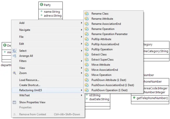
The mapping table and the set of refactoring operations corresponding to the example are summarized in Figure 6. To produce the list of refactored OCL constraints, we use the Roclet tool [13]. This tool offers the capability of refactoring both UML models and their associated constraints, by providing support for execution of basic refactoring operations, as shown in Figure 7. Within Roclet, we execute the set of refactoring operations, obtained by the Co-refTool, on the source model with its constraints. After executing these operations by stepwise adaptations, both the source model and the OCL constraints have been refactored. Using model comparison, we can then make sure that the latter model is the same as the target model, which was transformed using the initial “Black Box” transformation model. Thus, this result lets us assert that the ordered set of refactoring operations produced by our Co-refTool is
Figure 7: Using Refactoring Operations in Roclet
correct.
It is also important to note that this ordered set of operations is not the only one that could lead to the same target model. Indeed, multiple paths can lead to the same result, and this is due to the rules applied to define the order of operations. As Roclet transforms both a source model and its constraints, here below are the OCL constraints associated with the target model, automatically transformed thanks to the application of the refactoring operations:
c o n t e x t D e p a r t m e n t i n v M i n S a l a r y : s e l f . e m p l o y e e s −> s e l e c t ( e | e . s a l a r y <= s e l f . m i n S a l a r y )−> s i z e ( ) = 0 c o n t e x t Employee i n v O f f i c e N u m b D I F F o f f A r e a C o d e : s e l f . t e l e p h o n e N u m b e r . o f f i c e N u m b e r <> s e l f . t e l e p h o n e N u m b e r . o f f i c e A r e a C o d e c o n t e x t P r o j e c t i n v A t L e a s t T w o P r o j e c t M a n a g e r s : s e l f . e m p l o y e e −> f o r A l l ( d | d . c a t e g o r y −> s e l e c t ( e | e . n a m e C a t e g o r y = ’PM’ )−> s i z e () > =2 ) c o n t e x t D e p a r t m e n t i n v U n i q u e I d : s e l f . e m p l o y e e s −> c o l l e c t ( p | p . p r o j e c t s )−> a s S e t () − > f o r A l l ( p | p . i d −> s i z e () <= 1 ) c o n t e x t Employee i n v M a x T w o P r o j e c t : s e l f . p r o j e c t s −> a s S e t () − > s i z e () <= 2 c o n t e x t Employee i n v B a l a n c e P o s i t i f : s e l f . a c c o u n t s −> f o r A l l ( a | a . b a l a n c e > 0 ) c o n t e x t D e p a r t m e n t i n v D e p a r t M a n a g e r : s e l f . e m p l o y e e s −> e x i s t s ( e | e . name = ’ Manger ’ ) c o n t e x t Employee i n v :
s e l f . c a t e g o r y . n a m e C a t e g o r y <> ’ ’
In this case study, we showed how to apply our approach for the co-refactoring of models and their OCL con-straints. The use of Roclet for the actual refactoring of OCL constraints allows to produce syntactically correct constraints with a preserved semantic [25].
6. Related Work
Our work concerns mainly three aspects of model transformations: refactoring of OCL constraints attached to UML class models, transformation of OCL constraints to simplify them and finally the traceability.
In [11], the authors have presented an approach to transform OCL constraints for each basic operation of refac-toring. Their approach is complementary to ours because our solution is based on their results. Similarly in [12], the author proposes a method for transforming constraints that allows for the extension of a mapping defined on a few model elements, which is called interpretation function. This function is used first to redesign UML class diagram models. The same function is re-used to automatically translate the OCL constraints. The applicability of the approach is demonstrated in the case of UML class diagrams models refactoring. Our approach is very similar to this approach. Indeed, refactoring is a special case of redesign. However, their approach is theoretical and its implementation is not obvious.
In [26], the authors propose to improve badly structured OCL constraints by identifying OCL bad smells (such as duplicate code in the constraint). This is done for only very limited extent relationships between OCL constraints and the underlying class diagram. In [27], the authors propose an approach to assist the designer during the definition of the constraints by means of automatically transforming the initially defined constraints into equivalent alternatives by changing the context of the constraints. The proposed approach is formalized as a path problem over a graph representing the diagram. Each path between two vertices corresponds to a different context to represent the set of constraints defined over the first vertex. In [28], the authors propose an approach to simplify the OCL constraints generated in the context of design pattern instantiation templates, i.e., constraints expressing requirements associated with patterns. They identify various kinds of rules that are needed for OCL simplification and pointed out differences to usual term rewriting systems. All these work concern the second category defined above. Indeed, the simplification of constraints is complementary to our work. As we do not insure that the transformed constraint is optimal, a step for simplification may be very useful.
Our work is also concerned by techniques and frameworks for traceability and model comparison. Concerning traceability, some related work have been discussed in Section 3. Besides the fact that traceability is an output artifact of a model transformation, it can also be the result of applying techniques of versioning. The latter is necessary in the context of MDE [29, 30, 31], because it can help to manage the evolution of models. The use of algorithms developed for control systems, such as CVS and SVN, is incongruous in the context of MDE because the comparison is made at a low-level [32]. Concerning model comparison techniques, the UMLDiff approach described in [23] is very interesting because it can incorporate the semantics of the target language to provide more accurate results. However, this needs to specify the complete matching algorithm manually, which can be a particularly challenging task and this advantage comes at a high price [33].
There are other approaches, which can be also used to compare models, like SiDiff [34]. This approach is based on assigning a weight to each element in the models through a configuration file. The disadvantage of this approach is the difficulty for establishing and fine-tuning the weights of the features, which needs empirical trials and is an error-prone process. As such, finding the exact values of weights that deliver the best results for a particular modeling language can be particularly challenging.
7. Conclusion and Future work
Refactoring is a very important activity in the life cycle of software, because it improves its quality without changing its external behavior. In the Model Driven Engineering context, refactoring is expressed using endogenous transformation models. The constraints that annotate the source model, which aim is to reduce the number of valid instances, are unfortunately omitted or manually rewritten. We have presented an approach to transform OCL con-straints attached to a model after its refactoring. It is true that our approach applies only with some assumptions.
Among these assumptions is the assumed knowledge of the transformation language to select a mark that does not interfere with the latter. However, this assumption is not restrictive because in most cases the designer knows the used transformation language. The interest of our solution is that it avoids rewriting the transformation model to trace model elements. And as we have shown, the trace of model elements is not enough to easily translate OCL constraints. We built our solution based on already approved results [11]. This has advantages as well as disadvantages. The most important advantage is that part of the problem is already solved. Among disadvantages, the most important one concerns restrictions for possible extensions given the context of the solution. Indeed, we inherit all the restrictions of the solution. For example, we had planed to use the proposed approach to transform architectural constraints as proposed in [35]. However, the context of the transformation is exogenous (different metamodels). But, the solution proposed in [11] is not applicable for exogenous transformation. So, as future work, we intend to use a graph representation of the constraint, and using the mapping table, bring the problem to a graph transformation.
References
[1] T. Mens, G. Taentzer, D. Müller, Challenges in model refactoring, in: Proc. 1st Workshop on Refactoring Tools, University of Berlin, 2007. [2] T. Mens, T. Tourwé, A survey of software refactoring, IEEE Trans. Software Eng. 30 (2) (2004) 126–139.
[3] D. B. Roberts, Practical analysis for refactoring, Ph.D. thesis, University of Illnois at Urbana-Champaign. [4] M. Fowler, Refactoring: Improving the Design of Existing Code, Addison-Wesley, Boston, MA, USA, 1999. [5] T. Mens, P. V. Gorp, A taxonomy of model transformation, Electr. Notes Theor. Comput. Sci. 152 (2006) 125–142. [6] OMG, Unified Modeling Language: Superstructure, version 2.1.1, Object Management Group (February 2007).
[7] M. Boger, T. Sturm, P. Fragemann, Refactoring browser for uml, in: NetObjectDays, Vol. 2591 of Lecture Notes in Computer Science, Springer, 2002, pp. 366–377.
[8] G. Sunyé, D. Pollet, Y. Le Traon, J.-M. Jézéquel, Refactoring UML models, in: Proceedings of UML 2001, Vol. 2185 of LNCS, Springer Verlag, 2001, pp. 134–148.
[9] J. Warmer, A. Kleppe, The Object Constraint Language: Getting Your Models Ready for MDA, Addison-Wesley Longman Publishing Co., Inc., Boston, MA, USA, 2003.
[10] OMG, Object Constraint Language Specification, version 2.0, Object Modeling Group (June 2005). URLhttp://www.omg.org/spec/OCL/2.0/
[11] S. Markovic, T. Baar, Refactoring ocl annotated uml class diagrams, Software and System Modeling 7 (1) (2008) 25–47. [12] P. Kosiuczenko, Redesign of uml class diagrams: a formal approach, Software and System Modeling 8 (2) (2009) 165–183. [13] R. Team, Roclet project, Tech. rep. (2007).
[14] B. Ramesh, Representing and reasoning with traceability in model lifecycle management, Annals Operations Research 54 (1997) 123–145. [15] N. Aizenbud-Reshef, B. T. Nolan, J. Rubin, Y. Shaham-Gafni, Model traceability, IBM Syst. J. 45 (3) (2006) 515–526.
[16] O. C. Z. Gotel, A. C. W. Finkelstein, An analysis of the requirements traceability problem, in: 1st IEEE International Requirements Engi-neering Conference (RE 94) Proceedings, 1994, pp. 94–101.
[17] R. F. Paige, G. K. Olsen, D. S. Kolovos, S. Zschaler, C. Power, Building model-driven engineering traceability classifications, in: 4th ECMDA Traceability Workshop, 2008.
[18] OMG, MOF QVT Final Adopted Specification, Object Management Group (June 2005). URLhttp://www.omg.org/spec/QVT/1.0/
[19] F. Jouault, Loosely coupled traceability for atl, in: Proceedings of the European Conference on Model Driven Architecture (ECMDA) workshop on traceability, 2005.
[20] J. R. Falleri, M. Huchard, C. Nebut, Towards a traceability framework for model transformations in kermeta, in: In: ECMDA-TW Workshop, 2006.
[21] M. Alanen, I. Porres, Difference and union of models, in: UML, Springer-Verlag, 2003, pp. 2–17.
[22] D. Ohst, M. Welle, U. Kelter, Differences between versions of uml diagrams., in: ESEC / SIGSOFT FSE, ACM, 2003, pp. 227–236. [23] Z. Xing, E. Stroulia, Umldiff: an algorithm for object-oriented design differencing, in: ASE ’05: Proceedings of the 20th IEEE/ACM
international Conference on Automated software engineering, ACM, New York, NY, USA, 2005, pp. 54–65. [24] R. Wieringa, An introduction to requirements traceability, Tech. rep., Amsterdam ,Netherlands (1995). [25] S. Markovic, Model refactoring using transformations, Ph.D. thesis, Lausanne (2008).
[26] A. L. Correa, C. M. L. Werner, Applying refactoring techniques to uml/ocl models, in: UML, Springer-Verlag, 2004, pp. 173–187. [27] J. Cabot, E. Teniente, Transforming ocl constraints: a context change approach, in: SAC, 2006, pp. 1196–1201.
[28] M. Giese, D. Larsson, Simplifying transformations of ocl constraints, in: MoDELS, 2005, pp. 309–323.
[29] A. Cicchetti, D. Ruscio, A. Pierantonio, Managing model conflicts in distributed development, in: MoDELS ’08: Proceedings of the 11th international conference on Model Driven Engineering Languages and Systems, 2008, pp. 311–325.
[30] E. Visser, J. Warmer, A. V. Deursen, A. V. Deursen, driven software evolution: A research agenda, in: In Proc. Int. Ws on Model-Driven Software Evolution held with the ECSMR’07, 2007.
[31] K. Altmanninger, P. Brosch, G. Kappel, M. S. Philip Langer, K. Wieland, M. Wimmer, Why model versioning research is needed!? an experience report, in: Vortrag: Joint MoDSE-MCCM 2009 Workshop - Models and Evolution, Denver, USA, 2009.
[32] T. Mens, A state-of-the-art survey on software merging, IEEE Trans. Software Eng. 28 (5) (2002) 449–462.
[33] D. S. Kolovos, D. D. Ruscio, A. Pierantonio, R. F.Paige, Different models for model matching: An analysis of approaches to support model differencing, in: Proceedings of the 2009 ICSE Workshop on Comparison and Versioning of Software Models, CVSM ’09, IEEE Computer Society, Washington, DC, USA, 2009, pp. 1–6.
[34] C. Treude, S. Berlik, S. Wenzel, U. Kelter, Difference computation of large models, in: ESEC-FSE ’07: Proceedings of the the 6th joint meeting of the European software engineering conference and the ACM SIGSOFT symposium on The foundations of software engineering, ACM, New York, NY, USA, 2007, pp. 295–304.