Science Arts & Métiers (SAM)
is an open access repository that collects the work of Arts et Métiers Institute of Technology researchers and makes it freely available over the web where possible.
This is an author-deposited version published in: https://sam.ensam.eu Handle ID: .http://hdl.handle.net/10985/10271
To cite this version :
Farid ABED-MERAIM, Ron PEERLINGS, Marc GEERS - Comparison of bifurcation analysis and maximum force criteria in the prediction of necking in stretched metal sheets - 2015
Any correspondence concerning this service should be sent to the repository Administrator : archiveouverte@ensam.eu
Science Arts & Métiers (SAM)
is an open access repository that collects the work of Arts et Métiers ParisTech researchers and makes it freely available over the web where possible.
This is an author-deposited version published in: http://sam.ensam.eu Handle ID: .http://hdl.handle.net/null
To cite this version :
Farid ABED-MERAIM, Ron PEERLINGS, Marc GEERS - Comparison of bifurcation analysis and maximum force criteria in the prediction of necking in stretched metal sheets - 2015
Any correspondence concerning this service should be sent to the repository Administrator : archiveouverte@ensam.eu
COMPARISON OF BIFURCATION ANALYSIS AND MAXIMUM
FORCE CRITERIA IN THE PREDICTION OF NECKING IN
STRETCHED METAL SHEETS
F. ABED-MERAIM*, R.H.J. PEERLINGS† AND M.G.D. GEERS†
*
Laboratoire d’Étude des Microstructures et de Mécanique des Matériaux LEM3, UMR CNRS 7239, Arts et Métiers ParisTech
4 rue Augustin Fresnel, 57078 Metz Cedex 3, France e-mail: farid.abed-meraim@ensam.eu, www.ensam.eu
†
Department of Mechanical Engineering Eindhoven University of Technology
P.O. Box 513, 5600 MB Eindhoven, The Netherlands e-mail: R.H.J.Peerlings@tue.nl - M.G.D.Geers@tue.nl
Key words:Diffuse Necking, Stretched Metal Sheets, Bifurcation Analysis, Maximum Force Criteria, Critical Necking Strains, Formability Limits.
Abstract. In the present work, diffuse necking is investigated for stretched metal sheets using
two different approaches, namely bifurcation theory and maximum force principle. The contribution includes a critical analysis and a systematic comparison of their respective ability to predict necking. In particular it is shown that, in contrast to bifurcation theory, which is of quite general applicability, some restrictions are associated with the application of maximum force conditions. It is noteworthy that the well-known Swift diffuse necking criterion is recovered through bifurcation analysis. Recall that Swift’s criterion has long been attributed in the literature to the maximum force principle, while it is shown here to rather originate from the bifurcation analysis, which provides it with a sound theoretical justification.
1 INTRODUCTION
In the literature dealing with plastic instabilities, in general, and especially those related to material (local) instabilities in relation to sheet metal forming analysis, a large number of necking and formability criteria have been proposed. However, a thorough and rigorous comparison of their theoretical foundations and underlying assumptions is still lacking. An exhaustive list of those criteria is difficult to be given, considering the multitude of variants derived from some approaches. A short review reveals, however, that those criteria could be classified into at least four distinct categories, depending on their fundamental basis as well as their theoretical or physical background.
Early instability criteria were based on the maximum force principle, originating from Considère [1] and its two-dimensional extension by Swift [2] for application to metal sheets. These criteria, in their original form, were known to predict diffuse necking. Later, these maximum-force-based criteria were extended by Hora et al. [3] in order to predict localized
necking. Concurrently, Hill’s zero-extension criterion [4] was developed to predict localized necking on the left-hand side of the forming limit diagram (FLD).
Another approach, postulating a pre-existing defect in the material sheet, was proposed by Marciniak and Kuczyński [5]. In its original version, the Marciniak–Kuczyński (M–K) model can be regarded, in a sense, as a complementary approach to Hill’s zero-extension criterion, which is only applicable to left-hand side of FLDs as no zero-extension direction exists for positive biaxial stretching. However, since localized necking in biaxial stretching is observed in practice, a geometric imperfection has to be introduced in the M–K model to capture this phenomenon, which may provide some justification to this imperfection theory. This model was subsequently extended by Hutchinson and Neale [6] to the prediction of the left-hand side of the FLD by allowing the imperfection band to rotate until a localized neck is detected.
Drucker’s [7] and Hill’s [8] theory of loss of material stability, also referred to as the general bifurcation criterion, represents another class of approaches for necking prediction. Belonging to the same class, limit-point bifurcation appeared later [9], and it has been shown that for associative elasto-plasticity, limit-point bifurcation coincides with general bifurcation. For localized necking, Rudnicki and Rice [10,11] established a bifurcation criterion based on loss of ellipticity (i.e., singularity of the acoustic tensor), also known as the discontinuous bifurcation criterion. In the same way, some authors suggested the use of loss of strong ellipticity [12,13], which was shown to coincide with Rice’s criterion for associative elasto-plastic models.
A final significant class of criteria concerns those based on stability theory. Within this approach, necking and localization phenomena are tackled by stability analysis of the local equilibrium equations. The starting point is the mathematical concept of stability, introduced by Lyapunov [14] and commonly applied to structural instability problems (see, e.g., [15,16]). The associated technique of linear perturbation was extended to material instability problems by Molinari and Clifton [17]. To investigate the rate of growth of the perturbation, its governing equations are linearized, and the resulting eigenvalue problem will characterize stable and unstable modes. For strain-rate dependent material models, this approach could be regarded as an interesting alternative to bifurcation theory; the latter is known not to apply for strain-rate sensitive materials.
From the above overview of the various approaches for necking and localization prediction, an interesting observation can be made. Indeed, while the M–K analysis and Maximum Force Criteria (MFC) have been widely used in the literature, few applications of bifurcation theory to sheet metal formability have been published, which were initially mostly restricted to simple constitutive models (see, e.g., Doghri and Billardon [18]). Recently, Rice’s bifurcation criterion has been used to investigate formability limits of metallic materials (see, [19,20], using phenomenological constitutive modeling, and [21], using micromechanical approaches). Besides its sound theoretical basis, this bifurcation criterion has also been shown to provide a useful tool to investigate the impact of microstructural mechanisms on the formability limit of multiphase polycrystalline materials [22,23].
In the present contribution, attention is restricted to diffuse necking predictions applied to the in-plane stretching of metal sheets. Although the investigation of diffuse necking, as an approach to formability limits, may be seen as conservative when compared to localized necking predictions, there is yet a need for the former analysis. Besides its evident academic interest, explicit expressions for the critical hardening moduli allow loading paths, which are
less favorable to necking, to be selected, and can therefore be used in experiments specifically designed for the material parameter identification relying on mechanical tests with homogeneous deformation. To this end, two approaches are thoroughly investigated, namely the maximum force principle and the bifurcation approach. Their respective ability to predict this type of geometric instability phenomena are systematically compared for different work-hardening models.
2 BOUDARY VALUE PROBLEM
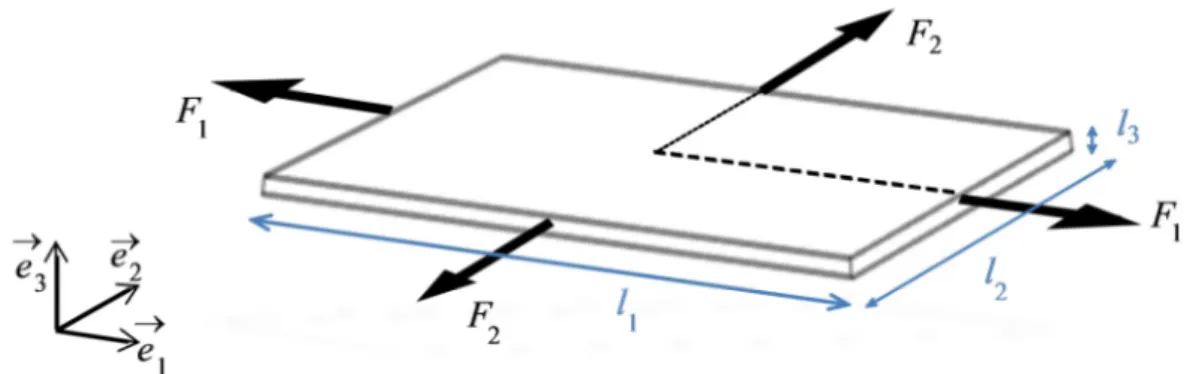
The problem statement is given here by describing the associated boundary value problem. Let us consider a metal sheet as illustrated in Fig. 1, which is subjected to in-plane biaxial loading conditions. The problem geometry is defined by its current parameters l , 1 l , 2 l , and 3
their initial values L , 1 L , 2 L , which denote the dimensions along the major strain direction, 3 the minor strain direction and the thickness direction, respectively.
Figure 1: Illustration of a metal sheet subjected to in-plane biaxial loading
The sheet is stretched by applying an in-plane biaxial loading
(
F1( )
λ , F2( )
λ)
on its lateral edges, whereλ
( )
t is a monotonously increasing function acting as a load control parameter, while the upper and lower surfaces (i.e., normal to the sheet thickness) remain traction free. Only isotropic material models are considered in this work so that the principal directions of stresses and strains remain parallel to the loading directions (1, 2).3 FUNDAMENTAL EQUILIBRIUM PATH
Subjecting the metal sheet shown in Fig. 1 to in-plane biaxial stretching results in an initially homogeneous stress and strain state, referred to as the fundamental path, to which bifurcation analysis and maximum force principle will be subsequently applied. The investigation will be conducted under plane-stress conditions and rigid–plastic constitutive modeling. The strain and stress tensors εεεε and σσσσ, associated with this fundamental solution, are given by their corresponding matrices ε and σ with respect to the Cartesian basis as
(
)
1 1 2 2 1 2 0 0 0 0 0 0 , 0 0 0 0 0 0 0ε
σ
ε
σ
ε ε
ε = σ = − + . (1)Let us first consider a general form of elasto-plastic constitutive equations with incompressible elasticity and isotropic hardening. This constitutive framework, despite its simplicity, can include a large variety of work-hardening models as typically used in sheet metal forming. Using the additive decomposition of the strain rate tensor into its elastic and plastic parts εεεεɺe and εεεεɺp, respectively, the elasticity law reads
( )
2 3 1 tr 2 2 e p E E = − = − I ɺ ɺ ɺ ɺ ɺ ε ε ε σ σ εε ε εε ε σσ σσ ε ε ε σ σ , (2)where E is the Young’s modulus, tr
( )
stands for the trace operator, and I2 denotes the second-order identity tensor. The plastic strain rate tensor is given by the usual associative flow rule p F p∂ = ∂ ɺ ɺ εεεε σσσσ, (3)where pɺ denotes the plastic multiplier and F the yield surface, here given by
( )
p eqF =σ −Y ε , (4)
in which
σ
eq = 3 2σ σσ σσ σσ σ′ ′: is the von Mises equivalent stress, function of the deviatoric stress tensor σσσσ′. Y is the yield stress describing isotropic hardening, which is a function of the equivalent plastic strainε
p, with εɺp = 2 3 p: pɺ ɺ
ε ε ε ε ε ε
ε ε .
Making use of the consistency condition, the plastic multiplier can be determined along with the elasto-plastic tangent modulus in the following particular tensorial form:
( )
2(
)
2(
)
3 1 3 1 tr : 2 2 2 eq E Eσσσσɺ − E σσσσɺ I = −εεɺεε E+hσ
σ σ εσ σ εσ σ εσ σ ε′⊗ ′ ɺ, (5)in which h=dY d
ε
p is the scalar hardening modulus. The case of rigid-plasticity, which is of interest here, can be recovered from the previous equations in the limit of E→ +∞. The plastic strain rate, thus equal to the total strain rate, is given by the same flow rule (3), with the plastic multiplier given by pɺ =ε
ɺp =ε
ɺ. Therefore, the rigid-plasticity constitutive equations are simply deduced from Eq. (5), as a special case, under the tensorial form(
)
2 3 1 : 2σ
eq ′⊗ ′ = ɺ ɺ ε σ σ ε ε σ σ ε ε σ σ ε ε σ σ ε, (6)(
)
(
)
(
)
(
)
1 2 2 1 1 1 2 2 2 1 2 2 1 1 2 2 3 2 2 3 2 2 eq eqε ε
σ σ ε σ ε
σ
ε ε
σ σ ε σ ε
σ
+ = + + = + ɺ ɺ ɺ ɺ ɺ ɺ ɺ ɺ (7)By setting
β ε ε
= ɺ2 ɺ1, a constant parameter that characterizes the proportional in-plane loading path (β
∈ −[
1 2 , 1]
, e.g., β = −1 2 for uniaxial tension (UT),β
=0 for plane-strain tension (PT),β
=1 for equibiaxial expansion (EBE)), it can be shown thatσ σ α
ɺ2 ɺ1= , with the following relationship betweenβ
andα
:2 1 1 2 2 2
α
β
β
α
α
β
− + = ⇔ = − + . (8)Making use of these proportionality factors, the rigid–plastic constitutive equations can be rewritten in a more compact form
(
)
(
)
1 1 2 1 2 2 3 2 1 2 3 h h σ β ε σ β ε = + = + ɺ ɺ ɺ ɺ (9)Integrating the above equations, the fundamental quasi-static equilibrium solution, which is indicated by superscript 0, can be obtained as follows:
( )
( )
(
)
( )
( )
0 0 1 1 1 0 0 1 0 0 0 0 , 0 0 0 0 1 0 0 0λ
ε λ
β
λ σ λ
α
β
ε = σ = − + , (10)in which
ε λ
1 =( )
t acts as a loading control parameter (with( )
0, for 1 1Y t
λ
=σ
<σ
), and(
)
( ) 1 1 0 2 2 3 t Y h d λσ
=σ
+ +β
∫
λ
, (11)with
σ
1Y =σ
yα α
2− +1, and σy the initial yield stress.For a linear hardening model, for which the hardening modulus h is constant, a closed-form solution can be easily obtained, while nonlinear hardening models require numerical integration. In all cases, the following convenient relationship can be derived:
2 1 2 1 3
β
β
ε
= + +ε
. (12)In fact, Eqs. (10,11) represent a one-parameter family of fundamental paths, and for each value of parameter
α
orβ
corresponding to a particular loading path, we can investigate the bifurcation or maximum force criteria.4 MAXIMUM FORCE PRINCIPLE
This classical approach was coined by Considère [1] who observed that necking occurs in a rounded bar under uniaxial tension when the applied load reaches a maximum. This earlier one-dimensional necking criterion has subsequently been extended to biaxial loading conditions by Swift [2]. Note that both the Considère and Swift’52 criteria are known to predict diffuse necking, which generally occurs prior to localized necking in the context of sheet metal forming. For the prediction of localized necking, Hora et al. [3] extended Considère’s criterion by taking into account the strain-path evolution after diffuse necking towards a plane-strain tensile state. It is worth noting that this class of criteria, referred to as the MFC, is noticeably popular in the literature and has been widely applied to determine FLDs at diffuse or localized necking. In this section, attention is restricted to diffuse necking by reconsidering the basic equations on which the Considère and Swift’52 criteria are based.
4.1 General considerations on the applicability of the MFC
For the above-described sheet under stretching (see Fig. 1), the quasi-static equilibrium equations in terms of the principal Cauchy stress components (
σ
1,σ
2) read1 1 2 3 2 2 1 3 F l l F l l σ σ = = (13)
For bifurcation analysis or application of MFC, the rate form of the equilibrium equations is usually more convenient. The latter, making use of the incompressibility condition, reads
1 1 1 1 2 3 2 2 2 2 1 3 F l l F l l σ σ ε σ σ ε = − = − ɺ ɺ ɺ ɺ ɺ ɺ (14)
In the one-dimensional case, Eq. (141) leads to the well-known expression of Considère’s
criterion (i.e.,
σ ε
ɺ1 ɺ1 =dσ
1 dε σ
1= 1), which expresses that necking starts when the uniaxial hardening modulus h=dσ
1 dε
1 drops to the value of the stress.For biaxial loading, the extension by Swift [2] suggests the application of the MFC at a simultaneous maximum of the forces. However, the simultaneous occurrence of maximum forces is only possible for some trivial loading paths. This has been demonstrated through experiments (see, e.g., Habbad [24]), but can also be shown by further analyzing Eqs. (14). Prescribing a linear loading path characterized by a constant parameter
β ε ε
= ɺ2 ɺ1, and the corresponding stress ratioα
, as defined by Eq. (8), it is straightforward from Eqs. (14) and (8) that a simultaneous maximum of the forces is only possible for α =0 orβ
=1. The firstcase, α =0, corresponds to the uniaxial tensile (UT) test, and the second,
β
=1, to equibiaxial expansion (EBE). Note that for both cases, the simultaneous maximum amounts to the condition of a maximum of the force along the major strain direction. Indeed, in UT the second conditionσ σ ε
ɺ2− 2 2ɺ =0, derived from Eq. (142), is obviously always satisfied, since2 0 2 0
F = ⇒
σ
= . For EBE, the symmetry of the problem reveals that condition (142) simplyreduces to condition (141).
To summarize, it has been shown that the condition of a simultaneous maximum of the forces (
σ σ ε
ɺ1 = 1 1ɺ andσ
ɺ2 =σ ε
2 2ɺ ) only occurs for two particular loading paths, whereas the condition of maximum force along the major strain direction (σ σ ε
ɺ1= 1 1ɺ ) may be possible for the whole range of loading paths that make up an FLD, and could therefore represent an alternative criterion. On the other hand, the condition of maximum force along the minor strain direction (σ
ɺ2 =σ ε
2 2ɺ ) is shown not to hold for some loading paths; therefore, this latter condition will no longer be investigated in the sequel.4.2 Application of the MFC along the major strain direction
Considering the limitations shown above as to the validity of the condition of simultaneous maximum of the forces, which restrict the range of applicability of the MFC, focus is confined to the maximum force condition along the major strain direction. Accordingly, for a linear loading path characterized by parameter
β
, the combination of the constitutive equations (9) and the maximum force condition along the major strain direction (i.e.,σ σ ε
ɺ1 = 1 1ɺ ) gives(
)
(
)
1 2 2 2 3 2 1 2 3 c c c c h hσ
β
σ
β
= + = + (15)The determination of the critical hardening modulus in Eq. (15) is achieved by solving the following equation given by the yield function F =0:
( )
2 1 1 c c Y σ α α− + = ε , (16)in which the critical stress σ1c
is replaced by its expression in terms of hc dY d c ε
ε
= .
Finally, the critical strains are given by
1 2 2 1 3 2 1 c c c c
ε
ε
β
β
ε
βε
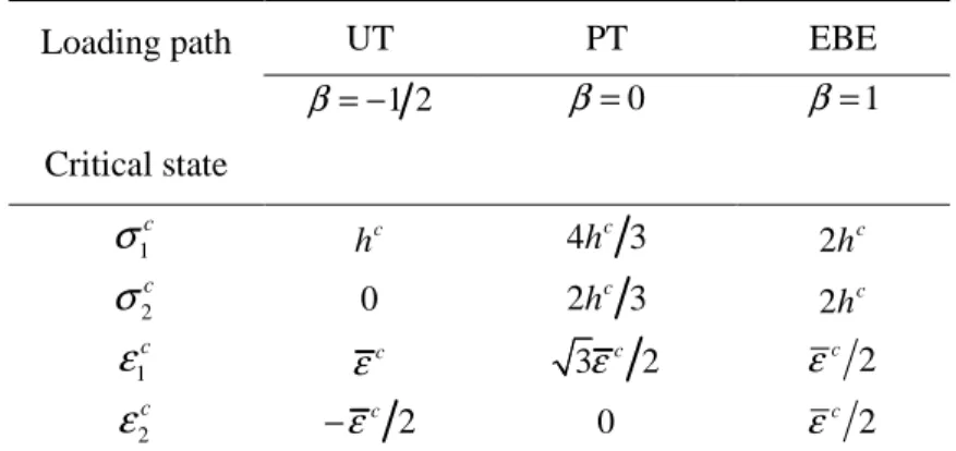
= + + = (17)For comparison purposes, Table 1 below gives the critical stress and strain states for three particular loading paths, namely UT, PT, and EBE.
Table 1: Critical states given by the MFC for three typical loading paths Loading path Critical state UT PT EBE 1 2 β= − β =0 β =1 1 c σ c h 4 c 3 h 2hc 2 c σ 0 2 c 3 h 2hc 1 c ε εc 3εc 2 2 c ε 2 c ε −εc 2 0 εc 2 5 BIFURCATION ANALYSIS
As discussed previously, the application of a biaxial loading state
(
F1( )
λ , F2( )
λ)
, which is characterized by the loading control parameterλ
( )
t , results in a quasi-static response indicated by superscript 0. This response(
ε λ σ λi0( )
, i0( )
)
, referred to as the fundamental equilibrium path, may exhibit bifurcation when the loading reaches a critical value. Theoretically, this means that the equilibrium equations may lose uniqueness for some critical values of the loading. The bifurcated solution, which intersects the fundamental equilibrium path, is characterized by the critical load and the associated bifurcation mode. For practical applications, the analysis of such instabilities amounts to solving an eigenvalue problem, in which one seeks the first eigenvalue, corresponding to the lowest critical load.5.1 General considerations on bifurcation analysis
The bifurcation equations are classically obtained by first assuming that there exist two different solutions for the rate equilibrium equations (i.e., the fundamental path and the bifurcated solution). Then, the corresponding governing equations (i.e., the rate equilibrium equations associated with these two solutions) are subtracted from each other when evaluated at the first bifurcation point. At this bifurcation point, where the two solutions intersect, there may be only loss of uniqueness for some rate variables; the non-incremental quantities themselves are equal at this point of onset of bifurcation. Applying this procedure to Eq. (14), which represents the rate equilibrium equations for the above sheet homogeneously deformed under stretching, the bifurcation equations are derived as follows:
0 1 1 1 0 2 2 2 0 0
σ σ ε
σ σ ε
∆ − ∆ = ∆ − ∆ = ɺ ɺ ɺ ɺ (18)where ∆ = −Aɺ Aɺ Aɺ denotes the difference between any rate variable Aɺ evaluated on the 0
To proceed further with the bifurcation analysis, the constitutive equations are required, so that the corresponding eigenvalue problem is completely defined and can therefore be solved. This will be done in the next section, where the superscript 0 will be omitted for conciseness.
5.2 Application of the bifurcation analysis
The bifurcation analysis in this context of rigid-plasticity involves two main equations. The first equation is obtained by combining the two equations in (7), which gives
(
σ
1−2σ
2)
∆ +ε
ɺ1(
2σ σ
1− 2)
∆ =ε
ɺ2 0. (19)The second bifurcation equation is derived starting from the consistency condition
( )
0eq
Fɺ =
σ
ɺ −Yɺε
= . By replacing the equivalent strain rate by the expression for the plastic multiplier pɺ =σ εσ εσ εσ ε:ɺ σeq , and making use of Eqs. (18), which are derived from the rate form of the equilibrium equations, the consistency condition leads to(
)
(
)
1 2 1 2 2h 1 2 2 2 1 2h 2 0
σ σ σ
− − ∆ +ε σ
ɺσ σ
− − ∆ =ε
ɺ . (20)The two-equation system associated with this bifurcation problem (i.e., Eqs. (19,20)) reads
(
1 2)
(
1 2)
1 1 1 2 2 2 1 2 2 2 K 0, with K 2 2h 2 2hσ
σ
σ σ
ε
σ σ σ
σ
σ σ
ε
− − ∆ = = ∆ − − − − ɺ ɺ . (21)The above linear algebraic system results in an eigenvalue problem, in which the bifurcation condition necessarily involves the singularity of matrix K, leading to
(
)
(
)
(
)
2 1 2 2 1 4 1 1 4 7 4 c c c c h α α σ α α α σ ασ − + = + − + = (22)The corresponding critical strains (ε1c, ε2c) can be obtained by considering Eqs. (16) and (17), where the critical equivalent strain
ε
c needs to be first determined by solving the generally nonlinear Eq. (16). Then, the associated critical hardening modulus hc is simply obtained by taking the derivative hc dY d cε
ε
= .
It is remarkable that Eq. (22), in conjunction with Eq. (16), is exactly the expression given by the Swift’52 diffuse necking criterion, which can be rewritten as
(
)
(
)
(
)
2 3/ 2 2 1 4 7 4 1 4 1 c dY Y d ε α α α ε α α + − + = − + . (23)This criterion has been frequently used in the literature to construct forming limit diagrams at diffuse necking for metal sheets. Table 2 below gives the critical stress and strain states for the three particular loading paths previously investigated.
Table 2: Critical bifurcation states for three typical loading paths Loading path Critical state UT PT EBE 1 2 β= − β =0 β =1 1 c σ c h 4hc 3 2hc 2 c σ 0 2hc 3 2hc 1 c ε εc 3εc 2 2 c ε 2 c ε −εc 2 0 εc 2
The results of Table 2, which are incidentally identical to those of Table 1 for these three specific loading paths, depend on the particular hardening law adopted. For loading paths other than those reported in Tables 1 and 2, it is on the contrary shown that the critical necking states predicted by bifurcation theory are different from those obtained by MFC.
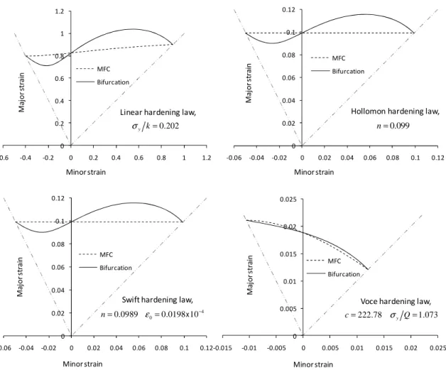
Figure 2: FLDs at diffuse necking given by bifurcation and MFC for four commonly used hardening laws
0 0.2 0.4 0.6 0.8 1 1.2 -0.6 -0.4 -0.2 0 0.2 0.4 0.6 0.8 1 1.2 MFC Bifurcation Minor strain M a jo r st ra in 0 0.02 0.04 0.06 0.08 0.1 0.12 -0.06 -0.04 -0.02 0 0.02 0.04 0.06 0.08 0.1 0.12 MFC Bifurcation M a jo r st ra in Minor strain Minor strain 0 0.005 0.01 0.015 0.02 0.025 -0.015 -0.01 -0.005 0 0.005 0.01 0.015 0.02 0.025 MFC Bifurcation M a jo r st ra in
Linear hardening law,
0.202 y k
σ =
Hollomon hardening law,
0.099 n= 0 0.02 0.04 0.06 0.08 0.1 0.12 -0.06 -0.04 -0.02 0 0.02 0.04 0.06 0.08 0.1 0.12 MFC Bifurcation M a jo r st ra in Minor strain
Swift hardening law, 4 0
0.0989 0.0198 10
n= ε = x −
Voce hardening law,
222.78 y 1.073
For the full range of loading paths investigated, Fig. 2 compares FLDs at diffuse necking obtained with the bifurcation approach and the MFC for a set of hardening models. These FLDs apply to copper foils modeled by rigid–plastic constitutive equations. The material parameters corresponding to four hardening models (i.e., linear, Hollomon, Swift, and Voce laws) have been identified using a uniaxial tensile experiment provided in [25], and the relevant values of these parameters are reported in Fig. 2.
Moreover, Fig. 2 reveals the impact of the selected material model on necking predictions. Both the shape and the level of the FLDs are strongly affected by the material model. As can be expected, a linear hardening model leads to unrealistically high limit strains, as opposed to the Voce model, which is a rapidly saturating hardening law providing the lowest FLDs. The intermediate hardening models of Hollomon and Swift, which give similar results, correspond to more commonly observed FLDs, and this is also supported by the fact that they fit the experimental UT data better.
6 CONCLUSIONS
In this paper, the basic equations underlying the bifurcation analysis and those relating to the maximum force principle have been first specified. Some restrictions to the maximum force conditions have been discussed. In particular, the simultaneous occurrence of the maximum of the forces is shown to be limited to some specific loading paths.
Throughout the analysis, the difference between the concepts of bifurcation and maximum force principle has been clearly evidenced. Moreover, these two distinct criteria have been systematically compared for rigid–plastic constitutive equations involving a variety of isotropic work-hardening models.
One of the main results of the present contribution is the fact that it was demonstrated that the Swift’52 necking criterion is founded on bifurcation theory rather than any maximum force condition. This provides a better justification for its wide application in the context of sheet metal forming. Indeed, the well-known expression given by the Swift’52 diffuse necking approach has been shown to be a natural outcome of the bifurcation analysis.
In the same way, Considère’s criterion in classical elasto-plasticity has been given full justification within the bifurcation theory, whereby its proper extension to multiaxial loading conditions should be undertaken within the same theory of bifurcation. Indeed, this theoretical approach not only provides a sound foundation to the MFC for some particular constitutive equations, but also proves to be applicable and reliable in more general situations.
REFERENCES
[1] Considère, A. Mémoire sur l’emploi du fer et de l’acier dans les constructions. Annales
des Ponts et Chaussées (1885) 9:574-775.
[2] Swift, H.W. Plastic instability under plane stress. J. Mech. Physics Solids (1952) 1:1-18.
[3] Hora, P., Tong, L. and Reissner, J. A prediction method of ductile sheet metal failure in FE simulation. Proc. of Numisheet 1996, Dearborn, Michigan, USA, (1996) pp. 252-256.
[4] Hill, R. On discontinuous plastic states, with special reference to localized necking in thin sheets. Journal of the Mechanics and Physics of Solids (1952) 1:19-30.
[5] Marciniak, Z. and Kuczyński, K. Limit Strains in the Processes of Stretch-Forming Sheet Metal. International Journal of Mechanical Sciences (1967) 9:613-620.
[6] Hutchinson, J.W. and Neale, K.W. Sheet Necking - II. Time-independent behavior. Mechanics of Sheet Metal Forming, Plenum Publishing Corporation, (1978) pp. 127-153.
[7] Drucker, D.C. On uniqueness in the theory of plasticity. Quarterly of Applied
Mathematics (1956) 14:35-42.
[8] Hill, R. A general theory of uniqueness and stability in elastic–plastic solids. Journal of
the Mechanics and Physics of Solids (1958) 6:236-249.
[9] Valanis, K.C. Banding and stability in plastic materials. Acta Mech. (1989) 79:113-141.
[10]Rudnicki, J.W. and Rice, J.R. Conditions for the localization of deformation in pressure-sensitive dilatant materials. J. Mech. Physics of Solids (1975) 23:371-394.
[11]Rice, J.R. The localization of plastic deformation. Proc. of the 14th International
Congress on Theoretical and Applied Mechanics, North-Holland Publishing Co., Delft,
Netherlands, (1976) pp. 207-220.
[12]Bigoni, D. and Hueckel, T. Uniqueness and localization – associative and non-associative elastoplasticity. International Journal of Solids Structures (1991) 28:197-213.
[13]Neilsen, M.K. and Schreyer, H.L. Bifurcations in elastic–plastic materials. International
Journal of Solids and Structures (1993) 30:521-544.
[14]Lyapunov, A. The general problem of stability of motion. Engl. Transl., Taylor and Francis, London, (1992).
[15]Abed-Meraim, F. Sufficient conditions for stability of viscous solids. Comptes Rendus de
l’Académie des Sciences - Series IIb - Mechanics-Physics-Astronomy (1999) 327:25-31.
[16]Abed-Meraim, F. and Nguyen, Q.S. A quasi-static stability analysis for Biot’s equation and standard dissipative systems. European J. Mechanics – A/Solids (2007) 26:383-393.
[17]Molinari, A. and Clifton, R. Analytical characterization of shear localization in thermo-visco-plastic solids. Journal of Applied Mechanics (1987) 54:806-812.
[18]Doghri, I. and Billardon, R. Investigation of localization due to damage in elasto-plastic materials. Mechanics of Materials (1995) 19:129-149.
[19]Abed-Meraim, F., Balan, T. and Altmeyer, G. Investigation and comparative analysis of plastic instability criteria: application to forming limit diagrams. International Journal of
Advanced Manufacturing Technology (2014) 71:1247-1262.
[20]Mansouri, L.Z., Chalal, H. and Abed-Meraim, F. Ductility limit prediction using a GTN damage model coupled with localization bifurcation analysis. Mechanics of Materials (2014) 76:64-92.
[21]Franz, G., Abed-Meraim, F., Ben Zineb, T., Lemoine, X. and Berveiller, M. Strain localization analysis using a multiscale model. Comput. Mat. Sci. (2009) 45:768-773.
[22]Franz, G., Abed-Meraim, F., Ben Zineb, T., Lemoine, X. and Berveiller, M. Role of intragranular microstructure development in the macroscopic behavior of multiphase steels in the context of changing strain paths. Mater. Sci. & Eng. A (2009) 517:300-311.
[23]Franz, G., Abed-Meraim, F. and Berveiller, M. Strain localization analysis for single crystals and polycrystals: towards microstructure–ductility linkage. International Journal
of Plasticity (2013) 48:1-33.
[24]Habbad, M. Instabilités plastiques en élasto-plasticité anisotrope et grandes déformations. Ph.D. thesis, Ecole Centrale de Lyon, (1994) France.
[25]Van der Sluis, O., Hsu, Y.Y., Timmermans, P.H.M., Gonzalez, M. and Hoefnagels, J.P.M. Stretching-induced interconnect delamination in stretchable electronic circuits.