Science Arts & Métiers (SAM)
is an open access repository that collects the work of Arts et Métiers Institute of Technology researchers and makes it freely available over the web where possible.
This is an author-deposited version published in: https://sam.ensam.eu Handle ID: .http://hdl.handle.net/10985/7466
To cite this version :
Guillaume FROMENTIN, Gérard POULACHON - Modeling of interferences during thread milling operation - The International Journal of Advanced Manufacturing Technology - Vol. 49, n°1, p.41-51 - 2010
1 2 3 4 5 6 7 8 9 10 11 12 13 14 15 16 17 18 19 20 21 22 23 24 25 26 27 28 29 30 31 32 33 34 35 36 37 38 39 40 41 42 43 44 45 46 47 48 49 50 51 52 53 54 55 56 57 58 59 60 61
Modeling of interferences during thread
milling operation
G. Fromentin, G. Poulachon
LaBoMaP, Dept. of Machining, Arts et Metiers ParisTech, 71250 Cluny, France
Email: [email protected]
Tel.: +33 3 85 59 53 30
Fax: +33 3 85 59 53 70
Keywords: thread milling, thread profile, tool profile, interference
Abstract: Thread milling is becoming more and more employed as a technique for producing thread, due to its advantages for industrial manufacturing sectors, such as the aeronautics, aerospace, and energy industries. The thread milling operation is atypical and several aspects have to be taken into account to perform it in good conditions. As for milling or grinding worms, grooves, thread or others sculptured surfaces, in thread milling, there exists a geometrical interference between the tool and the nominal surface which would be obtained. Thread mills have quite complex geometry and their profile has an effect on the machined thread. The present study details geometrical aspects of the thread milling process. This article deals with the link between thread mill geometry and nominal thread profile. An approach is proposed to analyze the thread profile generated by the thread mill envelope. It is deduced that thread milling produces interferences, i.e. the machined thread profile is affected by an overcut. A method is proposed to correct this geometrical error in order to produce accurate thread.
*Manuscript
1 2 3 4 5 6 7 8 9 10 11 12 13 14 15 16 17 18 19 20 21 22 23 24 25 26 27 28 29 30 31 32 33 34 35 36 37 38 39 40 41 42 43 44 45 46 47 48 49 50 51 52 53 54 55 56 57 58 59 60 61 62 NOMENCLATURE
Subscripts and abbreviations:
m relative to the mill
t relative to the thread
r,z cylindrical coordinates
Referentials and parameters:
RO = (O,E1,E2,E3) referential linked to the thread (O,E3): hole axis
Ro = (o, e1,e2,e3) referential linked to the mill with E3 = e3 and (E e1, 1)
t: time
: angular position of the mill :angular position of the mill axis
zce: altitude of a cutting edge point in the Ro referential
u: parameter
Metric thread characteristics:
D: nominal diameter of the internal thread
D1: minor diameter of the internal thread
D2: pitch diameter of the internal thread
R3: root radius of the internal thread (not standardized)
d: nominal diameter of the external thread
d1: minor diameter of the external thread
d2: pitch diameter of the external thread
R: root radius of the external thread
H: fundamental triangle height
P: thread pitch (mm)
p: angular thread pitch (mm/rad)
TD2: pitch diameter tolerance
td: thread direction (right-hand thread td = 1, left-hand thread td = -1)
1 2 3 4 5 6 7 8 9 10 11 12 13 14 15 16 17 18 19 20 21 22 23 24 25 26 27 28 29 30 31 32 33 34 35 36 37 38 39 40 41 42 43 44 45 46 47 48 49 50 51 52 53 54 55 56 57 58 59 60 61
Dmgt: maximum diameter of the generated thread
Er: radial error between nominal and generated thread
Er: variation of radial error along the thread flank
Mill dimensions:
Dm: maximum diameter (mm)
D2m: pitch diameter (mm)
km: reduction coefficient of the mill profile height
nfm: flute number
Cutting parameters:
Vc: cutting speed (mm/min)
ft: feed rate (mm/rev/tooth)
Rmc: helix radius of the mill center trajectory (mm)
Rmc cor: correction value of helix radius of the mill center trajectory (mm)
mm: milling mode (down-milling mm = 1, up-milling mm = -1)
Geometrical objects:
Pt i: i th
characteristic point of the nominal thread profile
Pm i: i th
characteristic point of the mill profile
MC(t): mill center trajectory
MP(zce): mill profile
ME(t,,zce): mill envelope
NTP(z): nominal thread profile
NTS(,z): nominal thread surface
MET(t,zce): mill envelope trace in the (O,E1,E3) plane
EMET(zce): envelope of the mill envelope trace in the (O,E1,E3) plane
GTP(z): generated thread profile
1 2 3 4 5 6 7 8 9 10 11 12 13 14 15 16 17 18 19 20 21 22 23 24 25 26 27 28 29 30 31 32 33 34 35 36 37 38 39 40 41 42 43 44 45 46 47 48 49 50 51 52 53 54 55 56 57 58 59 60 61 62 Ss: spindle speed (rpm)
: mill rotation speed (rad/s) : mill axis rotation speed (rad/s)
Vf: feed rate (mm/min)
Operators: R(): rotating operator cos( ) sin( ) 0 ( ) sin( ) cos( ) 0 0 0 1 R
1 2 3 4 5 6 7 8 9 10 11 12 13 14 15 16 17 18 19 20 21 22 23 24 25 26 27 28 29 30 31 32 33 34 35 36 37 38 39 40 41 42 43 44 45 46 47 48 49 50 51 52 53 54 55 56 57 58 59 60 61
1 Introduction
1.1 Generalities on thread milling
There are many methods to produce threads. The existing techniques may be classified into the following families: cutting, grinding, EDM, and
forming. Screws represent the majority of produced external threads, and they are obtained, in most cases, by a rolling process. Concerning internal threads, they are mainly machined with a cut tap. The thread milling
process is a method to machine both internal and external threads. Thread milling will probably not develop and become predominant as the two other threading techniques have. Nevertheless, thread milling has
advantages and is actually being used increasingly, to obtain, for example, large internal or external thread diameters [1-2].
Thread milling allows a high cutting speed, contrary to tapping, which requires a spindle inversion. Moreover, one thread mill may machine threads having a different nominal diameter and the same pitch. However, as explained below, a mill can not machine both an internal and external thread. In the case of an internal thread, the mill has a diameter less than the nominal diameter of the thread. If a tool breakage occurs, it can easily be removed, which may be problematic in tapping. As a consequence, an increasing use of thread milling is observed for the manufacturing of high-cost parts, such as aeronautical and aerospace parts made from super alloys.
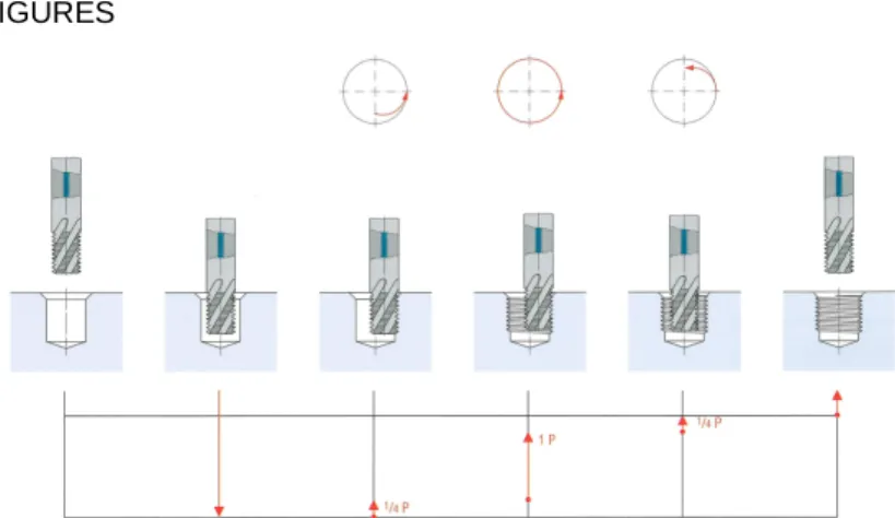
The thread mill envelope is composed of the thread pitch profile, and during the thread milling cycle, the tool center strategy describes a circular helix as shown in Fig. 1. It requires a helical interpolation, which nowadays
1 2 3 4 5 6 7 8 9 10 11 12 13 14 15 16 17 18 19 20 21 22 23 24 25 26 27 28 29 30 31 32 33 34 35 36 37 38 39 40 41 42 43 44 45 46 47 48 49 50 51 52 53 54 55 56 57 58 59 60 61 62
may be executed easily on a CNC machine. The mill is engaged in the radial direction along a quarter of helix. In this case, the thread is
machined along one tool path. It may also be machined along two or three paths, the radial penetration of the mill being incremented between each path. No previous research deals with this aspect, which merits closer study.
1.2 Surfaces machined with form tools and interference
Thread milling is a specific technique to produce threads, nevertheless with this, there exists a geometrical non-conformity to obtain desired final surface like for other techniques. The use of milling or of grinding with form tools for machining sculptured surfaces, worms, threads, grooves, flutes or helical gears leads to geometrical errors, named interference, which is an overcut (too much material is removed) or undercut (not enough material is removed). These errors can be corrected both by changing tool position during machining and by adapting tool profile. The first solution uses generally several computations with the interference model to minimize errors. The second solution needs a mathematical algorithm to define the tool profile as the function of the desired workpiece profile.
In five axis flank milling of free form surfaces with cylindrical mills, different methods may be possible for errors minimization by changing tool
positioning [3-5]. Further study also proposes to adapt tool shaped for better minimization of interference [6].
Worms, threads, flutes and grooves are mostly defined by helicoids which are mostly machined with a disk type tool [7-15] and sometimes with an axial type one [10]. There exists several methods to compute interference
1 2 3 4 5 6 7 8 9 10 11 12 13 14 15 16 17 18 19 20 21 22 23 24 25 26 27 28 29 30 31 32 33 34 35 36 37 38 39 40 41 42 43 44 45 46 47 48 49 50 51 52 53 54 55 56 57 58 59 60 61
errors (direct problem) and determine adapted tool profile (inverse
problem) having a different complexity, approximation levels. Studies are also focused on the numerical aspect for computing solution and the sensitivity of algorithm to solve tool profile determination [11-12].
No study is reported in the available literature concerning the interference during thread milling.
1.3 Context of study
There are very few studies on thread milling and they usually deal with the force modeling [16]. Because of the complexity of thread milling,
simplifying the kinematic approach is often considered. The aim of this study is to analyze and model, with the complete analytical approach, the thread mill profile and the resulted errors on the geometry of the generated thread. These errors may lead to obtain threads which do not respect the required quality. A method is proposed to correct geometrical errors by two combined means: an adaption of mill profile by the tool designer, and a modification the mill center trajectory by the mill user.
All calculations are computed using Mathematica software. It is focused on internal threads, because it represents the major application of thread milling, and because external thread milling induces minor problems of interference. Furthermore, it was decided to consider metric threads, which are internationally standardized. Nevertheless, the proposed method can easily be applied to other thread profiles as well.
Fig. 2 defines the parameterization of the internal thread milling operation. The (O,E1,E3) referential is linked to the thread and the (o,e1,e3) referential
1 2 3 4 5 6 7 8 9 10 11 12 13 14 15 16 17 18 19 20 21 22 23 24 25 26 27 28 29 30 31 32 33 34 35 36 37 38 39 40 41 42 43 44 45 46 47 48 49 50 51 52 53 54 55 56 57 58 59 60 61 62
is linked to the mill. The mill center (MC) position is a function of the time t. Other parameters are explained in further sections.
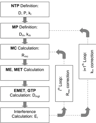
1.3 Used approach for the study
The approach in this study is described Fig. 3. A nominal thread profile (NTP) is defined; it represents the goal profile to machine. Then, the mill profile (MP) and a mill center trajectory (MC) are applied. It results a machined thread profile, named generated thread profile (GTP). This profile is not exactly equal to nominal thread profile (NTP), because of inferences, and this difference is quantified by a radial error (Er). Further, the goal will be to adapt mill center trajectory (MC) (ith loop) and the mill profile (MP) (i+1th loop) for reducing the error and obtaining a generated thread profile (GTP) as closer as possible to the nominal thread profile (NTP).
2 Metric thread profile
The metric thread profile is defined by ISO standard [17-18]. As shown in Fig. 4, the thread profile is based on the fundamental triangle and the basic profile. Basic dimensions are defined by equations (1) to (4). The internal diameter D1 of the internal thread is equal to the hole diameter before the threading operation. The internal thread profile is cut at a quarter of the thread height, while the external thread profile is cut at one eighth of the thread height. The root radius (R) of the external thread is standardized and must be higher than a minimum value in order to guarantee the strength of the screw. On the other hand, the root of the internal thread is not standardized, and its form (linear or circular) will depend on the design of the tool profile used for threading. The tool
1 2 3 4 5 6 7 8 9 10 11 12 13 14 15 16 17 18 19 20 21 22 23 24 25 26 27 28 29 30 31 32 33 34 35 36 37 38 39 40 41 42 43 44 45 46 47 48 49 50 51 52 53 54 55 56 57 58 59 60 61
designer has to respect only one constraint: the thread flank limits must be above the basic profile. This means that the diameter of the flank limits must be smaller than the nominal diameter (D) of the thread.
P p 2 (1) 3 H P 2 (2) 1 5 5 3 D D H D P 4 8 (3) 2 3 3 3 D D H D P 4 8 (4)
3 Thread and tool profile
This section describes the parameterization of the nominal thread profile (NTP), and the mill profile (MP).
3.1 Definition of the nominal thread profile
The nominal thread profile (NTP) is a thread profile which is required to be obtained after machining and which respects ISO standard [17]. It is
decided to define this nominal thread profile (NTP) by six points (Pti) linked
by lines as shown in Fig. 5. Their coordinates, in the (O,E1,E3) referential,
are given by equations (5) to (10). The external diameter, fixed to the root diameter, depends on the reduction coefficient of the thread profile height (kt). According to standard [17], this coefficient may not be greater than one eighth. In this study, the root form which is sought is flat. The nominal thread profile (NTP) is parameterized, in the RO referential, by equation (11) as function of z axis coordinate in the (O,E1,E3) referential. This
1 2 3 4 5 6 7 8 9 10 11 12 13 14 15 16 17 18 19 20 21 22 23 24 25 26 27 28 29 30 31 32 33 34 35 36 37 38 39 40 41 42 43 44 45 46 47 48 49 50 51 52 53 54 55 56 57 58 59 60 61 62
thread profile has a pitch diameter equal to the standard pitch diameter (D2). T T T t1r t1z P , P P. 5 3 /16,0 D/ 2,0 [ ] [ ] [ ] t1 P (5) T T T t 2r t 2z P , P P. 5 3 /16,1/ 8 D / 2,0 [ ] [ ] [ ] t2 P (6) T T T t3r t3z t t P , P P. 3(1/ 8 k ) / 2,8/16 k / 2 D / 2,0 [ ] [ ] [ ] t3 P (7) T T T t 4r t 4z t t P , P P. 3(1/ 8 k ) / 2,8/16 k / 2 D / 2,0 [ ] [ ] [ ] t4 P (8) T T T t5r t5z P , P P. 5 3 /16,7 / 8 D/ 2,0 [ ] [ ] [ ] t5 P (9) T T T t6r t6z P , P P. 5 3 /16,1 D / 2,0 [ ] [ ] [ ] t6 P (10) T r t1r t 2z t 2r t 2z t 3z t 2z t 3r t 2r t 2z t 3z r t 3r t 3z t 4z t 4r t 4z t 5z t 4z t 5r t 4r t 4z t 5z t 5r t 5z t 6z (z) TP (z), z P if z P P (z P ) /(P P ).(P P ) if P z P with NTP (z) P if P z P P (z P ) /(P P ).(P P ) if P z P P if P z P NTP [N ] (11)
The nominal thread surface (NTS), as a function of the nominal thread profile (NTP), may be analytically parameterized by equation (12). It is defined with cylindrical coordinates. The thread direction is defined by value td: td is equal to 1 or -1, respectively for a right-hand thread, and for a left-hand one. The thread direction (td) will change the mill center trajectory (MC) but without affecting the interference problem. This parameter is introduced for further studied aspects, such as the calculation of uncut chip thickness.
T T
d r
( , z) 0, 0, t .p. ( ). NTP (z), 0, z
NTS [ ] R [ ] (12)
3.2 Definition of the mill profile
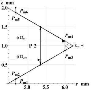
The maximum diameter of the mill is defined by Dm. It is also decided to define the mill profile (MP) by six points (Pmi) linked by lines. Their
1 2 3 4 5 6 7 8 9 10 11 12 13 14 15 16 17 18 19 20 21 22 23 24 25 26 27 28 29 30 31 32 33 34 35 36 37 38 39 40 41 42 43 44 45 46 47 48 49 50 51 52 53 54 55 56 57 58 59 60 61
coordinates, in the (o,e1,e3) referential, are given by equations (13) to (18).
The minor diameter is fixed, as the mill may not cut the minor diameter of the thread. The crest of the mill is defined by a reduction coefficient of the mill profile height (km). The mill profile (MP) is parameterized, in the Ro referential, by equation (19) as a function of the altitude zce of a cutting edge point. Fig. 6 shows an example of a mill profile (MP).
T T T m1r m1z m m P , P P. 3 3 / 8 3(1/ 8 k ) / 2,0 D / 2,0 [ ] [ ] [ ] m1 P (13) T T T m2r m2z m m P , P P. 3 3 / 8 3(1/ 8 k ) / 2,1/16 D / 2,0 [ ] [ ] [ ] m2 P (14) T T T m3r m3z m m P , P P. 0,8 /16 k / 2 D / 2, 0 [ ] [ ] [ ] m3 P (15) T T T m 4r m 4z m m P , P P. 0,8 /16 k / 2 D / 2, 0 [ ] [ ] [ ] m4 P (16) T T T m5r m5z m m P , P P. 3 3 / 8 3(1/ 8 k ) / 2,15/16 D / 2,0 [ ] [ ] [ ] m5 P (17) T T T m6r m6z m m P , P P. 3 3 / 8 3(1/ 8 k ) / 2,1 D / 2,0 [ ] [ ] [ ] m6 P (18) T ce r ce ce m1r ce m 2z m 2r ce m 2z m3z m 2z m3r m 2r m 2z ce m3z r ce m3r m3z m 4z m 4r ce m 4z m5z m 4z m5r m 4r m 4z ce m5z m5r m5z ce m6z (z ) MP (z ), z with P if 0 z P P (z P ) /(P P ).(P P ) if P z P MP (z ) P if P z P P (z P ) /(P P ).(P P ) if P z P P if P z P MP [ ] (19)
The pitch diameter of the mill is given by equation (20).
2m m m 3 D D P 1 2.k 2 (20)4 Milling parameterization
4.1 Definition of the mill center trajectory
The milling machine moves the mill center (MC) along a circular helix (Fig. 2). The helix pitch is equal to the thread pitch. Concerning its radius (Rmc),
1 2 3 4 5 6 7 8 9 10 11 12 13 14 15 16 17 18 19 20 21 22 23 24 25 26 27 28 29 30 31 32 33 34 35 36 37 38 39 40 41 42 43 44 45 46 47 48 49 50 51 52 53 54 55 56 57 58 59 60 61 62
a first proposal might be to determine the radial offset necessary to superimpose the pitch line of the two profiles as shown in Fig. 2 and Fig. 7. The approach is the same, whether the thread is milled in one pass or in several paths. This condition is represented by equation (21).
mc 2 2m 1 R D D 2 (21)From equations (20) and (21), the solution may be established; it is given by equation (22).
mc m m 1 3 1 R D D P k 2 2 8 (22)From this analysis, it can be established that the last points of the flank cutting edges which would cut as shown in Fig. 8.
r ce 1 mc ce inf .lim. ce sup.lim.
MP (z )D / 2 R z P / 8 or z 7.P / 8 (23) The spindle speed and the feed rate are determined with equations (24) and (25) as a function of cutting parameters (cutting speed and feed per revolution) and mill properties.
c S m 1000.V S .D (24) f fm t S V n .f .S (25)
Further, the mill rotation speed is given by equation (26). In the case of a modern machine tool applying the feed rate along the 3D trajectory, i.e. a circular helix, it may be demonstrated that the expression of the mill axis rotation speed around the hole axis is equation (27). It also takes into account the milling mode mm, which is equal to either 1 or -1; the milling operation is respectively down- or up-milling.
1 2 3 4 5 6 7 8 9 10 11 12 13 14 15 16 17 18 19 20 21 22 23 24 25 26 27 28 29 30 31 32 33 34 35 36 37 38 39 40 41 42 43 44 45 46 47 48 49 50 51 52 53 54 55 56 57 58 59 60 61 S .S 30 (26)
m fm t mc m .n .f . 2 . p² R ² (27)From the milling mode (mm) and the thread direction (td), the mill center trajectory (MC) is expressed by equation (28) in the RO referential.
T
mc mc d
(t) R .cos( .t), R .sin( .t), t .p. .t
MC [ ] (28)
4.2 Definition of the mill envelope
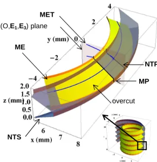
The mill envelope (ME) is the surface obtained by the revolution of the mill profile (MP) around the mill axis. From the previously defined elements, the surface of the mill envelope (ME) can be analytically formulated by equation (29) in RO referential. Fig. 8 shows this surface (ME) and the nominal thread surface (NTS) at a given time. Because of the helix angle of the nominal thread surface (NTS), it is clear that the mill envelope (ME) crosses the upper flank of the nominally defined thread surface. It also crosses the lower flank, but from the opposite side of the (O,E1,E3) plane.
This means that there is interference, which is an overcut on the thread flanks. T ce r ce ce (t, , z ) (t) ( ). MP (z ), 0, z ME MC R [ ] (29)
5 Interference parameterization
In order to parameterize the generated thread profile (GTP), the mill envelope trace (MET) in the (O,E1,E3) plane is observed. The mill
envelope trace (MET) represents the curve described by the intersection point of a circle contained in the mill envelope (ME) with this plane when mill moves, as shown Fig. 8. Equation (30) gives the value of parameter when the mill envelope (ME) intersects the (O,E1,E3) plane. Thus, this
1 2 3 4 5 6 7 8 9 10 11 12 13 14 15 16 17 18 19 20 21 22 23 24 25 26 27 28 29 30 31 32 33 34 35 36 37 38 39 40 41 42 43 44 45 46 47 48 49 50 51 52 53 54 55 56 57 58 59 60 61 62
trace can be analytically defined from equations (29) and (30) by
expression (31). It is the curve family equation in the (O,E1,E3) referential.
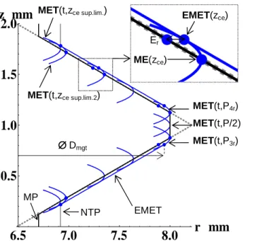
ce ce mc r ce (t, , z ). 0 (t, z ) arcsin R .sin( .t) / MP (z ) ME E2 (30) T ce ce ce ce ce (t, z ) (t, (t, z ), z ). , (t, (t, z ), z ). MET [ME E ME1 E ]3 (31)Fig. 9 shows curves representing the trace of specific points of the mill envelope (ME). Each point of the mill profile (MP) generates a trace which crosses over the nominal thread profile (NTP). As a consequence there is interference, and the overcut may be quantified by expressing a radial error (Er) (cf. Fig. 9). It can be seen that the points MP(zce inf.lim.) and MP(zce sup.lim.) are not the points of the mill profile which generated the interior points of the thread flanks. Thus equation (23) gives an
approximation, because it does not take into account the interference. The MET curves for any points of the mill profile represents a family of curves. There exits an envelope curve to this family of curves. The
envelope of the mill envelope traces (EMET) may be determined from the condition formulated by relation (32). The “f” function is calculated
numerically, and using equation (31) it is possible to obtain equation (33) of the envelope of the mill envelope traces (EMET) in the (O,E1,E3) plane.
This envelope is shown in Fig. 9 and it is the same on the upper and lower flank. ce ce ce ce ( (t, z ) ( (t, z ) DET 0 t f (z ) t z MET MET (32) ce ce ce (z ) (f (z ), z ) EMET MET (33)
1 2 3 4 5 6 7 8 9 10 11 12 13 14 15 16 17 18 19 20 21 22 23 24 25 26 27 28 29 30 31 32 33 34 35 36 37 38 39 40 41 42 43 44 45 46 47 48 49 50 51 52 53 54 55 56 57 58 59 60 61
Points MP(zce inf.lim.2) and MP(zce sup.lim.2) of the mill profile, which generated the interior points of the thread flanks, can be numerically calculated by solving equation (34). 1 ce inf .lim.2 D (z ). 2 EMET E1 (34)
From this analysis, the generated thread profile (GTP) is composed of several curves, among the upper and the lower envelopes of the mill envelope trace (EMET) and two mill envelope traces (MET). It is defined in pieces as in equation (35). Two of these are the envelopes of the mill envelope trace (EMET), which are the flanks. The root of the thread is composed of a vertical line and two mill envelope traces (MET), of points
MP(Pm3z) and MP(Pm4z). Points EMET(Pm3z) and EMET(Pm4z) may be considered as being the last points of the flanks. Next, the maximum diameter of the generated thread (Dmgt) is given by equation (36).
Whereas the mill profile (MP) considered does not have corner radius at points Pm3 and Pm4, the root of the generated thread does.
ce ce inf .lim 2 ce m3z m3z T mc m3r ce m3z ce m4z m4z ce ce sup.lim 2 ce m5z (z ) if z z P (t, P ) R P , z if P z P (t, P ) (z ) if z z P EMET MET [ ] GTP MET EMET (35) mgt m3z D = 2.EMET(P ).E1 (36)
In case A, the maximum diameter of the generated thread (Dmgt) is equal to 15.88 mm, which is less than the nominal diameter (D = 16 mm). As a consequence, because of the interference the flanks are not high enough to respect the ISO standard, despite the fact that the flank diameter is larger than it should be.
1 2 3 4 5 6 7 8 9 10 11 12 13 14 15 16 17 18 19 20 21 22 23 24 25 26 27 28 29 30 31 32 33 34 35 36 37 38 39 40 41 42 43 44 45 46 47 48 49 50 51 52 53 54 55 56 57 58 59 60 61 62
6 Results and interference correction
From the defined approach, the radial errors generated thread profile (GTP) during thread milling may be computed with the calculus software. The same results are also obtained with a CAD software which indicates that the programmed algorithm works. Moreover experimental
measurements on machined threads are made to check the model. Fig. 10 represents the radial error (Er) for case A. This error is not strictly constant, which means that the generated flank is not perfectly linear and the real flank angle is not equal to 60°. The radial error (Er) is higher on the external diameter (Er max = 57.3 m) of the flank than on the internal one (Er = 54.5 m), i.e. Er = 2.8 m. A mean least square line may be associated with the flank, which enables the straightness of the flank and its inclination to be calculated. In this case, straightness is equal to
0.05 m; this value is very low, and may consist mainly of a numerical computation error. Thus, the generated flank is very near to be linear. The real flank angle is 60.07 °, which is very near to what would be obtained nominally. Thus, the defects which occur because of the interference may be considered mainly as an offset of the profile.
The radial error is lower than half the tolerance interval (TD2/2 = 106 m) on D2 flank diameter defined for 4 quality thread. That means that
interference alone may not cause a non-standard thread; the defects on the milled thread also result from other sources such as mill deflection, vibrations and machine motion errors.
The algorithm for correcting overcut is described in Fig. 3. Because the interference is not constant along the flank, the method for correcting this
1 2 3 4 5 6 7 8 9 10 11 12 13 14 15 16 17 18 19 20 21 22 23 24 25 26 27 28 29 30 31 32 33 34 35 36 37 38 39 40 41 42 43 44 45 46 47 48 49 50 51 52 53 54 55 56 57 58 59 60 61
overcut could be to adapt the mill profile (MP) to the thread dimension which has to be milled. This solution is not satisfying, however; not only would it be complex, but then a thread mill could not be used for
machining threads having different diameters, because the interference is linked to the diameter. As a consequence, the solution which appears to suppress the overcut caused by interference is to correct the radius (Rmc) of the mill center trajectory (MC) (cf. Fig. 3 ith loop). This approach requires an increase of the mill triangular profile by decreasing the reduction
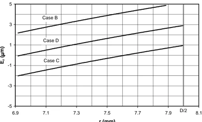
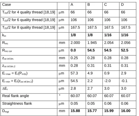
coefficient of the mill profile height (km) (cf. Fig. 3 i+1th loop), in order to obtain a sufficient maximum diameter of the generated thread (Dmgt). Fig. 11 and table 1 show the results of the iterative approach to interference reduction in order to obtain an internal thread having H tolerance classes. For case B, the radius (Rmc) is corrected from a radial correction value (Rmc cor), equal to the minimal radial error (Er min) obtained in case A, as explained by equation (37). Then, the coefficient (km) is decreased from case B (1/8) to C (1/16), in order to generate larger flanks. The change in the coefficient (km) also modifies the flank diameter of the thread mill, and it introduces a radial error which is not completely
corrected by the radial correction value (Rmc cor) established in case B. On the last step, from case C to D, the radius (Rmc) is corrected once more. After these three iterations, the variation in radial error (Er) is equal to 3 m and the maximum diameter of the generated thread (Dmgt) obtained is 16.00 mm, which appears to be an acceptable result.
mc m m mc cor mc cor r min
1 3 1 R i 1 D D P k R with R E i 2 2 8 (37)
1 2 3 4 5 6 7 8 9 10 11 12 13 14 15 16 17 18 19 20 21 22 23 24 25 26 27 28 29 30 31 32 33 34 35 36 37 38 39 40 41 42 43 44 45 46 47 48 49 50 51 52 53 54 55 56 57 58 59 60 61 62
If the goal is to obtain a thread outside the H tolerance classes, a radial correction value (Rmc cor) has to be adapted to the position of the tolerance interval.
7 Parameters influencing interference
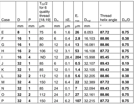
The model presented may be used for different cases by considering different thread and mill sizes. Table 2 sums up the data obtained. It appears that one significant parameter is the ratio between the mill diameter (Dm) and the nominal thread diameter (D). The lower this ratio is, the lower the overcut is. This may be easily understood but does not really constitute a method to minimize interference. For a given thread, the smaller the mill diameter (Dm), the more fragile the tool is. These two conflicting considerations are difficult to reconcile.
Interference is also influenced by the helix angle of the thread. For an identical mill diameter (Dm) and the same nominal thread diameter (D), the radial error (Er) increases with thread pitch (P). Effectively, the higher the helix angle of the thread, the more the mill bites into the nominal thread surface (NTS).
There is a third parameter which influences interferences; that is the thread profile itself. In this study, a metric thread is considered and there appears to be no interference induced by the front edge. The interference is generated by the flank edge. Flank orientation also has an influence on interference phenomena. The higher the inclination of the thread, the greater the overcut. This means that for square threads the overcut would be maximum.
1 2 3 4 5 6 7 8 9 10 11 12 13 14 15 16 17 18 19 20 21 22 23 24 25 26 27 28 29 30 31 32 33 34 35 36 37 38 39 40 41 42 43 44 45 46 47 48 49 50 51 52 53 54 55 56 57 58 59 60 61
8 Conclusion
Thread milling uses form tool for machining threads and may lead to interference with nominal thread surface. The present study proposed a model for radial errors due to interferences on milled threads. An analytical parameterization of the problem is defined without any simplification of the operation kinematics, the thread profile or the mill profile. The proposed approach considers the mill envelope. It enables an analysis of the effect of the thread mill profile on the generated thread profile. Moreover,
parameters influencing overcut are identified. Those which have an effect are: the thread helix angle, the mill diameter & thread diameter ratio and the flank angle of the thread profile. An iterative method is presented for reducing overcut by changing the radius of the helical interpolation and by adapting the mill profile.
1 2 3 4 5 6 7 8 9 10 11 12 13 14 15 16 17 18 19 20 21 22 23 24 25 26 27 28 29 30 31 32 33 34 35 36 37 38 39 40 41 42 43 44 45 46 47 48 49 50 51 52 53 54 55 56 57 58 59 60 61 62
References
1. Koelsch JR (2005) Thread milling takes on tapping. Manufacturing Engineer 115:77-83 2. Halas D (1996) Tapping vs thread milling Tooling and Production 62:99-102
3. Gong H, Cao LX, Liu J (2005) Improved positioning of cylindrical cutter for flank milling ruled surfaces. Computer-Aided Design 37(12):1205-1213
4. Lee JJ, Suh SH (1998) Interference-free tool-path planning for flank milling of twisted ruled surfaces. International Journal of Advanced Manufacturing Technology 14(11):795-805
5. Redonnet JM, Rubio W, Dessein G (1998) Side milling of ruled surfaces: Optimum positioning of the milling cutter and calculation of interference. International Journal of Advanced Manufacturing Technology 14(7):459-465
6. Chaves-Jacob J, Poulachon G, Duc E (2009) New approach to 5-axis flank milling of free-form surfaces: Computation of adapted tool shape. Computer-Aided Design, DOI: 10.1016/j.cad.2009.06.009
7. Bar G (1990) CAD of worms and their machining tools. Computer Graphics in the German Democratic Republic 14(3-4):405-411
8. Bar G (1997) Curvatures of enveloped helicoids. Mechanism and Machine Theory 32(1):111-120
9. Sheth DS, Malkin S (1990) CAD/CAM for geometry and process analysis of helical groove machining. Annals of the CIRP Manufacturing Technology 39(1):29–132
10. Kang SK, Ehmann KF, Lin C (1996) A CAD approach to helical groove machining Part 1: Mathematical model and model solution. International Journal of Machine Tools and Manufacture 36(1):141–153.
11. Kang SK, Ehmann KF, Lin C (1997) A CAD approach to helical groove machining. Part 2: Numerical evaluation and sensitivity analysis. International Journal of Machine Tools and Manufacture 37(1):101-117
12. Hsieh JF (2006) Mathematical model and sensitivity analysis for helical groove machining. International Journal of Machine Tools and Manufacture 46(10):1087-1096 13. Chiang CJ, Fong ZH (2009) Undercutting and interference for thread form grinding with a tilt angle. Mechanism and Machine Theory 44(11):2066-2078
14. Chiang CJ, Fong ZH, Tseng JT (2009) Computerized simulation of thread form grinding process. Mechanism and Machine Theory 44(4):685-696
15. Ahn JH, Kang DB, Lee MH, Kim HY, Kim SH, Cho KK (2006) Investigation of Cutting Characteristics in Side-milling a Multi-thread Worm Shaft on Automatic Lathe. Annals of the CIRP Manufacturing Technology 55(1):63-66
16. Araujo AC, Silveira JL, Jun MBG, Kapoor SG, DeVor R (2006) A model for thread milling cutting forces. International Journal of Machine Tools & Manufacture 46:2057– 2065
17. ISO 68-1:1998 standard, ISO general purpose screw threads - Basic profile - Part 1: Metric screw threads
18. ISO 965-1 standard, ISO general-purpose metric screw threads - Tolerances - Part 1: Principles and basic data
19. ISO 965-2 standard, ISO general purpose metric screw threads - Tolerances - Part 2: Limits of sizes for general purpose external and internal screw threads - Medium quality
FIGURES
Fig. 1 Thread mill machining cycle - source: Emuge (catalogue of thread mill supplier)
E2 E1 E3 e1 e2 Ø D Ø D Ø D 2 1 Θ = Ω.t θ = -ω.t R mc Ø D m o O 2m Ø D MC ME
Fig. 2 Parameterization of thread milling operation Figure
Fig. 3 Algorithm for interference calculation and correction R3 H/8 P /2 External thread R H/4 Internal thread P H ØD = Ød ØD2 = Ød2 ØD1 = Ød1
Fig. 4 Metric ISO standardized thread profile
NTP Definition:
D, P, kt
MP Definition:
Dm, km
ME, MET Calculation
EMET, GTP Calculation: Dmgt MC Calculation: Rmc Interference Calculation: Er i+ 1 th L o o p : km c o rr e c ti o n i th L o o p : R m c c o rr e c ti o n
Fig. 5 Nominal thread profile (NTP) - case A: D = 16 mm, P = 2 mm, kt = 1/8
Fig. 6 Mill profile (MP) - case A: P = 2 mm, Dm = 12 mm, km = 1/8
P 2 Pm1 Pm2 Pm3 Pm4 Pm5 Pm6 5.0 5.5 6.0 r mm 0.5 1.0 1.5 2.0 z mm km.H φ D2m φ Dm P 2 Pt1 Pt2 Pt3 Pt4 Pt5 Pt6 7.0 7.5 8.0 r mm 0.5 1.0 1.5 2.0 z mm kt.H φ D2 φ D1
P 2 Pm inf.lim. Pm sup.lim. 7.0 7.5 8.0 r mm 0.5 1.0 1.5 2.0 z mm
Fig. 7 Superposition of nominal thread profile (NTP) and mill profile (MP) - case A: D = 16 mm, P = 2 mm, kt = 1/8, Dm = 12 mm, km = 1/8, Rmc = 2 mm
Fig. 8 3D Visualization of profiles and surfaces - case A: D = 16 mm, P = 2 mm, td = 1,
kt = 1/8, Dm = 12 mm, km = 1/8, Rmc = 2 mm ME NTS overcut (O,E1,E3) plane MET MP NTP
Fig. 9 Generated thread profile (GTP) - case A: D = 16 mm, P = 2 mm, kt = 1/8,
Dm = 12 mm, km = 1/8, Rmc = 2 mm
Fig. 10 Radial error (Er) on the flanks of the generated thread profile (GTP) - case A:
D = 16 mm, P = 2 mm, kt = 1/8, Dm = 12 mm, km = 1/8, Rmc = 2 mm 7.0 7.2 7.4 7.6 7.8 8.0r mm 45 50 55 60 Er m ∆Er Er max Model Measured points Er min 6.5 7.0 7.5 8.0 r mm 0.5 1.0 1.5 2.0 z mm Er EMET MET(t,P4r) MET(t,P/2) MET(t,P3r) MET(t,zce sup.lim.) MET(t,zce sup.lim.2) EMET(zce) ME(zce) ∅ ∅∅ ∅ Dmgt NTP MP
-5 -3 -1 1 3 5 6.9 7.1 7.3 7.5 7.7 7.9 8.1 r (mm) Er (µµµµ m ) Case B Case C Case D D/2
Case A B C D TD2/2 for 4 quality thread [18,19] m 66 66 66 66
TD2/2 for 6 quality thread [18,19] m 106 106 106 106
TD2/2 for 8 quality thread [18,19] m 167.5 167.5 167.5 167.5
km 1/8 1/8 1/16 1/16 Rmc mm 2.000 1.945 2.054 2.056 Rmc cor m 0.0 54.5 54.5 52.5 zce inf.lim. mm 0.25 0.28 0.28 0.28 zce inf.lim.2 mm 0.28 0.31 0.31 0.31 Er max = Er(Pm3z) m 57.3 4.9 0.9 2.9 Er min = Er(zce inf.lim.2) m 54.5 2.2 -2.0 -0.1 Er m 2.8 2.7 3.0 3.0
Real flank angle ° 60.07 60.07 60.07 60.07 Straightness flank m 0.05 0.05 0.06 0.06
Dmgt mm 15.88 15.77 15.99 16.00
Table 1 Results of interference modeling for cases A to D: D = 16 mm, P = 2 mm, D1 = 13.835 mm, D2 = 14.701 mm, kt = 1/8, Dm = 12 mm
Table
Case D P TD2/2 for 6 quality thread [18,19] Dm Er Er max Dmgt Thread helix angle Dm/D mm mm m mm m m mm E 8 1 75 6 1.6 26 8.053 87.72 0.75 F 16 1 80 6 0.4 2.8 16.103 88.86 0.38 G 16 1 80 12 0.4 13 16.081 88.86 0.75 H 16 2 106 12 3.1 53 16.108 87.72 0.75 I 16 4 ND 12 28.4 204 15.998 85.45 0.75 J 32 1 85 6 0.1 0.5 32.107 89.43 0.19 K 32 1 85 12 0.1 1.4 32.105 89.43 0.38 L 32 2 112 12 0.8 5.6 32.205 88.86 0.38 M 32 4 150 12 6.4 22 32.389 87.72 0.38 N 32 1 85 24 0.1 7 32.094 89.43 0.75 O 32 2 112 24 0.7 27 32.161 88.86 0.75 P 32 4 150 24 6.2 107 32.215 87.72 0.75
Table 2 Results of interference modeling for cases E to P: kt = 1/8, km = 1/16,
gif movie 1 for visualizing interference
gif movie 2 for visualizing interference