HAL Id: hal-00788133
https://hal.archives-ouvertes.fr/hal-00788133
Submitted on 13 Feb 2013
HAL is a multi-disciplinary open access
archive for the deposit and dissemination of
sci-entific research documents, whether they are
pub-lished or not. The documents may come from
teaching and research institutions in France or
abroad, or from public or private research centers.
L’archive ouverte pluridisciplinaire HAL, est
destinée au dépôt et à la diffusion de documents
scientifiques de niveau recherche, publiés ou non,
émanant des établissements d’enseignement et de
recherche français ou étrangers, des laboratoires
publics ou privés.
Level-based peer-to-peer live streaming with rateless
codes
Eliya Buyukkaya, Shakeel Ahmad, Muneeb Dawood, Jiayi Liu, Raouf
Hamzaoui, Gwendal Simon
To cite this version:
Eliya Buyukkaya, Shakeel Ahmad, Muneeb Dawood, Jiayi Liu, Raouf Hamzaoui, et al.. Level-based
peer-to-peer live streaming with rateless codes. ISM 2012: IEEE International Symposium on
Multi-media, Dec 2012, Irvine, United States. �10.1109/ISM.2012.54�. �hal-00788133�
Level-based peer-to-peer live streaming with
rateless codes
Eliya Buyukkaya
∗Shakeel Ahmad
†Muneeb Dawood
†Jiayi Liu
∗Fen Zhou
‡Raouf Hamzaoui
†Gwendal Simon
∗∗
Institut Mines-T´el´ecom - T´el´ecom Bretagne, France,
{firstname.lastname}@telecom-bretagne.eu
†De Montfort University, United Kingdom,
{sahmad, mdawood, rhamzaoui}@dmu.ac.uk
‡
LIA / CERI, University of Avignon, France,
{fen.zhou}@univ-avignon.fr
Abstract—We propose a peer-to-peer system for streaming user-generated live video. Peers are arranged in levels so that video is delivered at about the same time to all peers in the same level, and peers in a higher level watch the video before those in a lower level. We encode the video bitstream with rateless codes and use trees to transmit the encoded symbols. Trees are constructed to minimize the transmission rate for the source while maximizing the number of served peers and guaranteeing on-time delivery and reliability at the peers. We formulate this objective as a height bounded spanning forest problem with nodal capacity constraint and compute a solution using a heuristic polynomial-time algorithm. We conduct ns-2 simulations to study the trade-off between used bandwidth and video quality for various packet loss rates and link latencies.
I. INTRODUCTION
The last five years have seen the emergence of online video platforms that enable users to broadcast their own live video [1]–[3]. This user-generated content typically con-sists of reality TV, shows, concerts, or, as in Xfire [4] and TwitchTV [5], live streams from online gamers.
A major problem faced by these platforms is that not all user-generated content is popular. Consequently, thousands of live video streams need to be simultaneously streamed to only a small number of clients. This poses a serious challenge to the existing content delivery infrastructures, which have not been designed for that purpose. An alternative solution is to use a peer-to-peer (P2P) system.
This paper describes a P2P system developed within the CNG project [6]. The goal is to enable Massively Multiplayer Online Game (MMOG) players to stream screen-captured video of their game. Players can use the system to show their skills, share experience with friends, or coordinate missions in strategy games. In this context, the video source is any casual gamer, whose network and computer resources are used for the game. It is therefore critical to minimize the transmission rate at the source.
In addition, from discussions with stakeholders in the Inter-net TV and gaming communities, we have identified another requirement, which has not been addressed in previous P2P works. The idea is that peers are arranged in levels such that live video is delivered at the same time to all peers in the same level. Moreover, peers in a higher level should be able to watch the video before those in a lower level. This level-based model is a generic way to implement a number of practical features: • in a tiered or freemium service (two popular business models where users are charged according to the quality
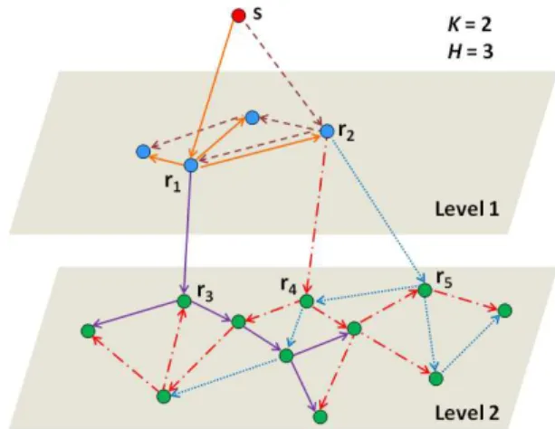
Fig. 1: Video diffusion within and across levels via multicast trees. Example where five trees are used: two in Level 1 (higher level) rooted at r1 and r2 and three in Level 2 (lower level) rooted at r3, r4, and r5. A node must receive K = 2 packets to decode the video. A packet cannot be forwarded more than three times in a tree (H = 3).
of service received), a level is a priority class. Users in the same class have the same playback lag. Moreover, users in a higher class have a lower playback lag than those in a lower class.
• in MMOGs, a level can be defined as a virtual area within the game. Players that are located in one particular area watch a live stream of another player at the same time, which ensures fairness and consistency. Moreover, the playback lag for a player increases with increasing distance to the source of the video.
• in eSport systems (broadcast of live sport events), a level is associated with physical areas. Two people watching the same event and close enough to physically interfere have the same playback lag. This aims to prevent the annoying situation where viewers react to an event (e.g., shouting “goal” in a football match) before it has occurred on the screen of their neighbors.
We design a multi-level P2P system, which consists of peers and a P2P server. The P2P server has persistent communication with the peers and is responsible for building the P2P overlay. Multicast trees are used to diffuse video data within and across levels (Fig. 1). We use rateless codes [7] to provide
resilience against packet loss. Rateless codes are probabilistic erasure codes that can recover k information symbols from any received k(1+ǫ) encoded symbols with high probability. Here ǫ is a small positive number that gives the trade-off between the error recovery property of the code and the amount of redundancy it introduces. Rateless codes are ideally suited for our application as they (1) have very low computational cost, (2) minimize delivery redundancy when a peer receives data concurrently from multiple peers, (3) make the system adaptive to varying channel conditions since the encoder can generate on the fly as many encoded symbols as needed.
The use of rateless codes for P2P video streaming was introduced by Wu and Li [8]. As soon as a receiving peer successfully decodes the source block, it becomes a source and applies rateless coding on the decoded source block to generate encoded symbols for other peers. Grangetto, Gaeta, and Sereno [9] improved this seminal work by introducing a method, called ’Relay and Encode’ (RE), where a receiving peer immediately relays the received encoded symbols. The authors show that RE has a lower delay than the method of [8]. In [10], they introduced feedback so that peers can stop receiving symbols when a block is decoded.
We introduce two new contributions to P2P live video systems: we design a new multi-level architecture, which aims at guaranteeing that all peers within the same level play the video at the same time, and we propose a novel algorithm to efficiently schedule the rateless encoded packets within and across levels. Our algorithm tries to build multicast trees that minimize the transmission rate for the source while maximizing the number of served peers and guaranteeing on-time delivery and reliability at the peers. We formulate this objective as a height bounded spanning forest problem with nodal capacity constraint and compute a solution in polynomial-time.
The remainder of the paper is as follows. In§II, we describe the video transmission scheme. In §III, we present our tree construction algorithm. In §IV, we use ns-2 simulations to test our P2P system. Finally, we give our conclusions in §V.
II. TRANSMISSION SCHEME
Initialization. A peer wishing to broadcast its video requests the P2P server to advertise it. This peer is called the source. If another peer is interested in the advertised video, it sends a request to the P2P server. Like a tracker (a server of peerlists in traditional P2P systems), the P2P server is in charge of updating the overlay information and informing the participating peers. The overlay information consists of peer assignments to levels and sets of multicast trees for each level (see §III). The overall overlay is denoted by G(V, E) where V is the set of peers and E is the set of links. An arc between u and v is denoted by (u, v).
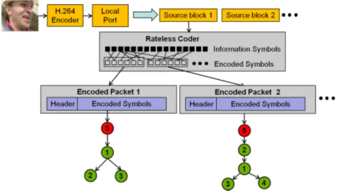
Video and channel coding. As soon as the source receives the overlay information from the P2P server, it captures the video and compresses it with the H.264 video coder [11]. The resulting bitstream is partitioned into source blocks, where each source block corresponds to one GOP (Group of Pictures) and is an independent unit of fixed playback duration∆.
Fig. 2: Video coding and streaming. Node s denotes the source. Packet 1 is sent over a multicast tree to peers 1, 2, and 3. Packet 2 is sent to peers 2, 1, 3, and 4.
Then the source applies rateless coding on each source block and sends the resulting encoded symbols in successive UDP packets. Packets are transmitted in an interval of duration ∆ with a uniform inter-departure time, and one packet is sent on each multicast tree (Fig. 2).
Inter-level communication. A root of a Level 1 multicast tree (r1 and r2 in Fig. 1) immediately forwards packets directly received from the source to the Level 2 multicast trees associated to it (one tree for r1and two trees for r2in Fig. 1). Moreover, as soon as it successfully decodes a source block, it sends an acknowledgment to the source, so that the source stops sending it packets, and it creates new encoded packets by applying rateless coding on the decoded source block. Then it sends these new encoded packets to Level 2 peers over the multicast trees associated to it (ignoring those already used). To reduce the probability that a Level 2 peer receives duplicate packets, Level 1 root peers use randomly chosen rateless code seedswhen they encode a source block. The value of the seed is sent as part of the packet header. The number of packets sent by a Level 1 root peer to Level 2 is set not to exceed the number of Level 2 multicast trees associated to this root peer. The procedure described above for two levels is repeated for the next levels.
Level-Aware Timely Video Delivery. To ensure that all peers in the same level have the same playback lag, and peers in a higher level have a shorter playback lag than those in a lower one, the following procedure is followed.
All peers are synchronized in time. This can be achieved, for example, with the Network Time Protocol [12]. A time stamp is inserted in each UDP packet to indicate the start time of the current source block. All Level 1 peers play back the first GOP at time2∆+Dmax. Here Dmax= (H +1)×lmax, where H is the maximum height of a multicast tree and lmax is an estimation of the maximum latency between two nodes in the overlay. Thus 2∆ + Dmax is the latest possible arrival time for any packet from the first source block (Fig. 3).
When a Level 1 root peer completes the decoding of the first source block, it enters the re-encoding phase up to time2∆ + Dmax+ Ω. Here, Ω gives sufficient time to send re-encoded packets in case the decoding of the source block is delayed. As the packet loss rate increases, the decoding completion
Fig. 3: Transmission strategy.
time shifts towards2∆ + Dmax and more time is needed for sending re-encoded packets. We usedΩ = pmax∆ where pmax is an estimation of the maximum packet loss rate between two nodes in the overlay.
All Level 2 peers play back the first GOP at time 2∆ + 2Dmax+ Ω, which is the latest possible arrival time of any packet for the first source block. More generally, all peers at Level L play back the kth GOP at time(k + 1)∆ + LDmax+ (L−1)Ω. Thus, the playback lag for level L is 2∆+LDmax+ (L − 1)Ω.
III. FORMULATION OF THE VIDEO DIFFUSION PROBLEM
In §III-A, we formulate the problem of constructing an optimal forest for the diffusion of source blocks in one level. In §III-B, we explain the inter-level interactions in a multi-level overlay. We detail our forest construction algorithm in §III-C.
A. Intra-Level Multicast Trees
For simplicity, we consider only one level, so our goal is to deliver GOPs from a source s to a set of peers. The main idea is to use a multiple-tree structure for video diffusion. Each multicast tree (or tree, in short) is used to transmit one packet of encoded symbols from the source to the peers. To recover the video block, a peer should receive at least K packets of encoded symbols. In other words, a peer should belong to at least K trees.
There are constraints on the trees. A critical one is that every peer v ∈ V is associated with an upload capacity, denoted by cv, which is the number of packets the node v can transmit. This capacity constraint limits the number of children a node can have. In addition, to guarantee on-time delivery and reliability at the peers, the end-to-end delay and the packet loss rate on the path from the source to each peer should be bounded. This requirement thus imposes a bound on the height of each tree.
Our objective is to minimize the transmission rate for the source while guaranteeing recovery of the video block. The more trees are used to ensure that all peers receive at least K packets, the higher is the source transmission rate. Thus, minimizing the source transmission rate is equivalent to minimizing the number of trees. In light of this, we formu-late the video diffusion problem in the overlay as a Height-Bounded Spanning Forest problem with Capacity constraint (HBSFC). The goal of HBSFC is to find a forest F with minimum cardinality such that
• the number of trees is limited by source capacity cs. • each tree is rooted on a peer, which directly receives a
packet from the source s. In other words, we distinguish the source from the root of each tree.
• for each node v, the sum of its out-degrees in all trees of the forest is not greater than its capacity cv.
• each node is spanned in at least K trees. A node that cannot be spanned in K trees is rejected from the overlay. • the height of each tree is limited by a bound H. These constraints are imposed on every level. Before going into the details of the algorithm (see§III-C), we discuss inter-level capacity issues.
B. Multi-level overlay management
When the number of levels is greater than one, we have to make sure that the video can be relayed from one level to the next. We create inter-level connections for that purpose.
To simplify the management of the whole system, we pro-pose that the root peers in a level are in charge of transmitting data to the next level. Simply put, a root peer immediately forwards a packet it received directly from the previous level to the next level. In other words, a root peer in level l acts as a source for some root peers in level l+ 1. This strategy has three advantages: (i) there is no delay between the reception of a packet and its transmission to the next level, (ii) the inter-level connections are well distributed over peers because root peers are well distributed over the population, and(iii) the management of inter-level connections is easy for the P2P server: it only has to inform the root peers of every level about the trees in the next level.
We denote by Rl the set of Level l root peers. If there is no capacity issue, each root peer in level l should become a source of j|Rl+1|
|Rl|
k
trees in level l+ 1. The remaining trees are randomly allocated to the root peers.
Fig. 1 gives an example of a two-level overlay. Each peer in a level is spanned in two different trees, with height no more than three. Peers r1 and r2 are the root peers in level 1, while r3, r4 and r5 are the root peers in level 2, i.e., R1 = {r1, r2}, R2 = {r3, r4, r5}. Therefore, |R1| is equal to 2, while|R2| is equal to 3. Peers r1and r2 are the sources for trees in level 2. Peers r3 and r4 are connected to r1 and r2 respectively. To be the source of r5, r2 is then randomly selected between r1 and r2.
The management of peer capacity is a critical issue for the inter-level links. We explain how we solve this issue hereafter. A root peer should reserve some upload capacity to serve some peers in the next level. For any peer v, we distinguish
Algorithm 1 Resource Allocation and Overlay Algorithm Input: Complete graph G(V, E), a decomposition of V into L
disjoints subsets{V1, . . . , VL}, capacity cv for all v∈ V , and the number of packets K
Output: Forest Fl in each level l
1: |F1| ← cs
2: for l from1 to L − 1 do
3: Cnext← K × |Vl+1|
4: build forest Fl with Cnext and Vl
5: while forest Fl does not cover all peers in Vldo
6: if Cnext
> K then
7: Cnext← Cnext− 1
8: else ifP
v∈Vlcv> K then
9: reject v∈ Vl with minimum capacity
10: else
11: sacrifice Fl
12: re-build Vl such that Cnext=P
v∈Vlcv≥ K 13: break
14: end if
15: build forest Fl with Cnext and Vl
16: end while
17: |Fl+1| ← Cnext 18: end for
19: build forest FL with Cnext
= 0 and VL
the upload capacity ccurv that can be used to serve peers in the same level from the upload capacity cnextv that is secured to serve peers in the next level. Of course, ccurv + c
next
v ≤ cv for any peer v, and cnext
v = 0 if v is not a root peer or is a root peer at the lowest level.
The number of trees that are constructed in a level l depends on the amount of resources that have been secured by the root peers in the previous level. Formally, if we denote by Fl the forest in level l, we have: |Fl| =P
v∈Vl−1c
next v .
Once the number of trees for level l is given, we should both build the trees and determine the amount of capacities that must be secured for the next level l+ 1. On the one hand, we aim to maximize the number of peers that are covered in level l, i.e., the number of peers that are spanned in at least K trees of Fl. This objective calls for a highP
v∈Vlc
cur v . On the other hand, we have to guarantee that we reserve enough capacities for the next level. This objective calls for a high P
v∈Vlc
next
v .The two objectives conflict.
We propose a heuristic (see Alg.1), which is based on the following observation. The number of trees that should be constructed in order to serve all peers in a level is bounded:
K≤ |Fl| ≤ K × |Vl|
We suggest the following for resource allocation at level l. We start with the most optimistic scenario where P
v∈Vlc
next
v = K × |Vl|. We try to build a forest Fl with the remaining capacities. If all peers in Vlare covered at least K times in Fl, then both objectives are fulfilled and it ends the algorithm for level l. Otherwise, we have to revise the allocation of resources:
1) we reduce the amount of capacities secured for the next
level P v∈Vlc
next
v as long as this allocation still enables the construction of more than K trees in Fl+1(lines 6-7), 2) when we reach the tipping point for which
P v∈Vlc
next
v < K, we have to reject peers from level l to save more capacities. We choose to reject the peer v∈ Vlthat has the least capacity cv (lines 8-9), 3) finally, when the set of remaining peers Vl cannot gather
enough resources to serve the next level, a radical deci-sion should be taken: either level l+ 1 cannot be served (and all subsequent levels as well), or level l is sacrificed. We opt for the latter choice (lines 10-13).
C. Resource-Aware Multicast Trees
We detail now the algorithm for the construction of one intra-level overlay forest. This algorithm is a key routine called by Alg. 1 in lines 4, 15 and 19. This algorithm should consider the constraints described in§III-A (about the multicast trees) and§III-B (about the sharing of physical resources). It returns either a failed forest, or a forest containing the given number of trees such that all nodes are spanned in at least K trees. Algorithm 2 Forest construction algorithm
Input: Complete graph G(V, E), capacity cv for all v∈ V , Vl set of peers in level l (initially unspanned),
Cl=P v∈Vl−1c
next
v number of trees to build in level l, Cnext
l amount of resources to secure for level l+ 1, number of packets K, maximum height H
Output: Height-bounded forest Fl
1: for k from1 to Cl do
2: u← the unspanned node in Vl with max. capacity
3: p← a root node with spare capacity in Vl−1
4: create Tk
l = ({u}, ∅) with p as source
5: end for
6: secure capacity cnext
u from all root nodes u
7: if impossible to secure overall capacity Cnext l then
8: fail - end of the algorithm
9: end if
10: for k from1 to Cl do
11: for h from0 to H − 1 do
12: while∃u at height h: cu>0 and Vl\ Tk l 6= ∅ do
13: u← a node in Tlk at height h with cu>0
14: v← an unspanned node 6∈ Tlk
15: add{v} and edge (u, v) to Tk
l, update cu
16: if v is spanned in K trees then
17: mark v as spanned
18: end if
19: end while
20: end for
21: end for
22: if at least one node is still unspanned then
23: fail - end of the algorithm
24: else
25: Fl← {Tk
l ,∀k ∈ {1, . . . , Cl}}
26: end if
We give the pseudocode of our algorithm for level l in Alg. 2. Note that our implemented algorithm contains various
slight improvements, compared to this simplified version. This algorithm is based on two distinct steps.
First, we create the trees and we associate the roots (lines 1-5). The number of trees to generate is based on the resources secured by peers in level l− 1. The peers with maximum capacities are chosen as roots. Then, we secure the capacity for level l+ 1. If the roots do not have collectively enough capacities to secure the requested amount of capacity, then the algorithm ends with a failure notification.
Second, we build the trees in a breadth-first manner (lines 10-21). The choice of which unspanned peer to add to the trees (line 14) is done in two ways in our implementation: we choose the nodes with minimum spare capacity (or empty capacity) when the height is H, while we choose the nodes with maximum spare capacity otherwise. The algorithm suc-cessfully returns the forest Flif all peers are spanned K times.
IV. SIMULATION RESULTS
We used the ns-2 network simulator to test the performance of our system. We considered a scenario where the overlay consists of four levels with 10 peers in each level. The encoded symbols of the rateless code were sent in successive UDP packets of size S bytes each. The size of an encoded symbol was one byte. An accurate Raptor code model proposed in [13] was used to simulate Raptor coding. With this model, a redundancy of 5%, gives a high probability of successful decoding [13]. The diffusion forest construction algorithm was run with H = 3. The number of packets K used in the forest construction algorithm was determined by K = b∆(1+ǫ)8×S where b is the source bit rate in bps, ∆ is the transmission duration in s, and ǫ is the rateless code redundancy factor.
For the peer upload capacity, we used a log-normal distri-bution with a mean of 512 kbps. The second parameter of the distribution, σ, was 0.1. This corresponds to a homogeneous configuration where the upload capacity of all peers is close to the mean. The download capacity was 10 Mbps for all peers. For the link latencies, we followed [14] and used a log-normal distribution with mean 17.19 ms and variance 0.0029.
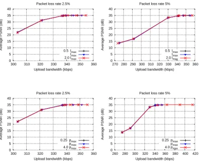
Fig. 4 shows the average received peak signal-to-noise ratio (PSNR) in the P2P network as a function of the average used upload bandwidth for two packet loss rates. When a source block was not recovered, the last successfully received frame was copied. Results are given for the CIF Foreman video sequence encoded at 30 frames per second and 320 kbps. The forest was constructed for a fixed number of multicast trees corresponding to a maximum of 60% redundancy by setting ǫ = 0.6 and S = 1000. The code redundancy was then varied by changing the packet size S, which changed the number of transmitted encoded symbols leading to different used bandwidths. We used S equal to 656, 688, 750, 812, 875, 938 and 1000 bytes corresponding to code redundancy 5%, 10%, 20%, 30%, 40%, 50% and 60%, respectively. The figures present results when the maximum network latency lmax (see §II) and the maximum packet loss rate pmax (see §II) were set to the actual values, as well as when they were estimated.
The results show that our system provided all peers with the highest achievable PSNR (35.07 dB) at low bandwidth cost.
0 5 10 15 20 25 30 35 40 300 310 320 330 340 350 360 Average PSNR (dB) Upload bandwidth (kbps) Packet loss rate 2.5%
0.5 lmax lmax 2.0 lmax 0 5 10 15 20 25 30 35 40 270 280 290 300 310 320 330 340 350 360 Average PSNR (dB) Upload bandwidth (kbps) Packet loss rate 5%
0.5 lmax lmax 2.0 lmax 0 5 10 15 20 25 30 35 40 300 310 320 330 340 350 360 Average PSNR (dB) Upload bandwidth (kbps) Packet loss rate 2.5%
0.25 pmax pmax 4.0 pmax 0 5 10 15 20 25 30 35 40 260 280 300 320 340 360 380 400 420 Average PSNR (dB) Upload bandwidth (kbps) Packet loss rate 5%
0.25 pmax
pmax
4.0 pmax
Fig. 4: Top: Average PSNR vs. average used upload bandwidth for the 320 kbps Foreman video when the value of lmax was the actual one, 100% higher, and 50% lower. Bottom: Average PSNR vs. average used upload bandwidth for the 320 kbps Foreman video when the value of pmax was the actual one, 300% higher, and 75% lower.
TABLE I: Raptor code redundancy to provide maximum video quality in the P2P network for various packet loss rates and transmission durations.
0% 2.5% 5%
∆ = 0.25 s 5% 60% 60%
∆ = 0.5 s 5% 60% 60%
∆ = 1 s 5% 50% 60%
They also show that our system is robust against a mismatch between the used values and the actual ones. We obtained similar results for video bit rates 640 kbps and 960 kbps, as well as for video sequences Mother and Daughter and Mobile. Fig. 5 shows the upload bandwidth used by the source to ensure that all 40 peers get maximum video quality. For a given packet loss rate, we ran simulations for different redundancies and used the one that maximized the PSNR (Table I).
The source transmission rate depends on the redundancy, loss rate, and the effectiveness of feedback. The source trans-mission rate increases with the loss rate because as the loss rate increases it delays the feedback. We also observe that when∆ decreased, the effectiveness of feedback also decreased. The source may have already sent all the data with the full selected redundancy before feedback arrives.
We now study the effects of peer leaving on the PSNR of the remaining peers. We simulated a pre-scheduled live broadcast event announced to all peers in advance. Each peer joined the system at the start of the event and remained online for an exponentially distributed time τ (with probability density
320 340 360 380 400 420 440 460 480 500 520 0 1 2 3 4 5 Upload bandwidth (kbps) Loss rate (%) ∆ = 0.25s ∆ = 0.5s ∆ = 1s
Fig. 5: Source transmission rate to provide maximum video quality in the P2P network for various packet loss rates and transmission durations. 0 5 10 15 20 25 30 35 40 0 100 200 300 400 500 Average PSNR (dB) Time (s) Static Peers leaving Recomputed overlay at t=45 Recomputed overlay at t=322 Num peers removed
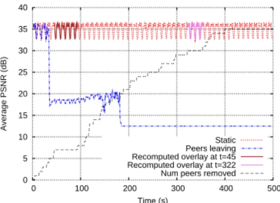
Fig. 6: Average PSNR in the P2P network vs. time. “Static”: no peer leaves. “Peers leaving”: peers leave according to curve “Num peers removed”. “Recomputed overlay at t=45”: P2P server reconstructs the overlay after 45 s. ‘Recomputed overlay at t=322”: P2P server reconstructs the overlay after 322 s.
function λe−λτ for τ ≥ 0 ) after which it left the system and did not rejoin. We used λ= 0.4 to ensure that at least a few peers stay in the system until the end of the session.
Fig. 6 shows the average PSNR of peers as a function of time. As more and more peers left the system, the average PSNR of the remaining peers dropped. The drop in PSNR is negligible after the first few departures but it increases significantly with further leaving of peers. However, the drop in PSNR can always be recovered by recomputing the overlay. This is shown by the average PSNR with recomputed overlay at times 45 s and 322 s when 7 and 30 peers had left respectively. The PSNR for the recomputed overlay is identical to the one where no peer leaves. The PSNR with recomputed overlay is shown only up to the time when the next peer leaves at which time the overlay can be recomputed.
V. CONCLUSION
We presented a P2P live video system that uses levels to define a hierarchy among peers. The system relies on rateless
coding and multicast trees for video diffusion. Multicast trees are built with a low-complexity polynomial-time algorithm that tries to minimize the source transmission rate while guaranteeing on-time delivery and reliability at the peers. Minimizing the source transmission rate is critical for user-generated video where the source usually has limited upload speed. Experimental results with the ns-2 network simulator showed that the system can offer high video quality to all peers at low bandwidth cost. The results also highlighted the benefits of rateless coding for fast delivery and robustness against packet loss.
The system was designed for a static scenario where all peers join before the start of the video session and remain subscribed until the end. Applications include team mates par-ticipating in an MMOG quest while sharing screen-captured video of their gameplay for coordination purposes. Since even for such applications one cannot exclude the eventuality that peers decide to leave, we tested the performance of the system accordingly. Simulations showed that the system can sustain high performance as long as the number of dropped peers is moderate. When too many peers leave, the performance can deteriorate suddenly because the probability that a vital peer is dropped increases. While such cases are unlikely to happen for the intended applications, they can always be handled by the following procedure. Keep-alive messages are periodically sent from the peers to the server. The server regularly checks if all peers send keep-alive messages within a given time interval. If a peer stops sending keep-alive messages, the server removes it from the overlay and updates the multicast trees.
ACKNOWLEDGMENT
The research leading to these results has received funding from the European Commission’s Seventh Framework Pro-gramme (FP7, 2007-2013) under the grant agreement no. ICT-248175 (CNG project). REFERENCES [1] Online. http://www.justin.tv/. [2] Online. http://www.livestream.com/. [3] Online. http://www.ustream.tv/. [4] Online. http://www.xfire.com/. [5] Online. http://www.twitch.tv/.
[6] Online. Available at: http://www.cng-project.eu/.
[7] A. Shokrollahi, “Raptor codes,” IEEE Trans. Inf. Theory, vol. 52, pp. 2551–2567, June 2006.
[8] C. Wu and B. Li, “rstream: Resilient and optimal peer-to-peer streaming with rateless codes,”IEEE Trans. Parallel Distrib. Syst., vol. 19, no. 1, pp. 77-92, 2008.
[9] M. Grangetto, R. Gaeta, and M. Sereno, “Rateless codes network coding for simple and efficient P2P video streaming,” in Proc. IEEE ICME, 2009. [10] M. Grangetto, R. Gaeta, and M. Sereno, “Reducing content distribution time in P2P based multicast using rateless codes,” in Proc. Italian Networking Workshop, pp. 1–12, Bologna, 2009.
[11] T. Wiegand, G. Sullivan, G. Bjontegaard, and A. Luthra, “Overview of the h.264/avc video coding standard,” IEEE Trans. Circuits and Systems for Video Technology,” vol. 13, no. 7, pp. 560–576, Jul. 2003. [12] D. Mills, “Network Time Protocol (Version 3) Specification,
Implemen-tation and Analysis. Request for Comments 1305, Internet Engineering Task Force,” 1992. http://www.rfc-editor.org/rfc/rfc1305.txt.
[13] M. Luby, T. Gasiba, T. Stockhammer, and M. Watson, “Reliable mul-timedia download delivery in cellular broadcast networks,” IEEE Trans. Broadcasting, vol. 53, pp. 235-246, 2007.
[14] A. Hernandez and E. Magana, “One-way delay measurement and characterization,” in Proc. ICNS ’07, Athens, Greece, June 2007.