Technology researchers and makes it freely available over the web where possible.
This is an author-deposited version published in: https://sam.ensam.eu Handle ID: .http://hdl.handle.net/10985/7547
To cite this version :
Michael J. WALOCK, Yujiao ZOU, Denis LAGADRILLERE, Corinne NOUVEAU, Andrei STANISHEVSKY - W-Cr-C-N Nanocomposite Thin-Film Coatings via Reactive Magnetron Sputtering - In: 54th Society of Vacuum Coaters Annual Technical Conference, United States, 2011-04 - 54th Society of Vacuum Coaters Annual Technical Conference Proceedings - 2011
Cr-W-C-N nanocomposite coatings via reactive magnetron sputtering
Michael J. Walocka,b, Yujiao Zoua, Denis Lagadrillereb, Corinne Nouveaub, and Andrei V.
Stanishevskya
aDepartment of Physics, University of Alabama at Birmingham, Birmingham, AL 35294-1170
USA
bLaboratoire Bourguignon des Matériaux et Procédés, CER Arts et Métiers ParisTech de Cluny,
71250 Cluny, France ABSTRACT
While binary tungsten carbide can form smooth, hard films, these suffer from low fracture toughness. Tungsten nitride films are frequently harder, but are more brittle. Chromium nitride has excellent wear and oxidation resistance, but films often form with low hardness. Composites of these binary compounds offer a possibility to tailor the material for a desired combination of properties. To this end, we have used reactive RF-magnetron sputtering with Cr and WC targets to form quaternary composites, with nitrogen as the reactive gas. The coatings were deposited on Si, Ti, and steel substrates. The nitrogen partial pressure was varied to investigate the relationship between the film properties and the deposition conditions. Energy dispersive spectroscopy showed changes in the chemical composition as a result of the change in nitrogen partial pressure. X-ray diffraction illuminated the structure as either a solid solution with a B1 NaCl structure, or a nanocomposite with the average crystallite size under 11 nm. Optical interferometer revealed low compressive stresses. And nanoindentation established that the films are hard and adherent.
I. INTRODUCTION
Tungsten carbide tools have played a prominent role since the beginning of the last century. In part, this is due to the material’s high melting point, high hardness, and high oxidation resistance [1]. However, it’s most stable form, h-WC, tends to be brittle and is easily damaged [2]. To counter this, a composite of metal (usually, cobalt) and tungsten carbide was formulated in the 1920s. This cemented-WC has excellent hardness, strength, and fracture toughness. Unfortunately, this improvement comes at the price of thermal stability. At temperatures as low as 600ºC, cemented-WC begins to oxidize and its strength begins to degrade [3]. In addition, the prominent wear mechanism seems to be preferential removal of the metal binder [4-6]. Today’s tools are typically coated with titanium-based compounds to improve the wear and oxidation resistance.
With its excellent mechanical, chemical, physical, and electronic properties, tungsten nitride has found use in a wide variety of applications. It has proven to be an effective diffusion barrier in microelectronics , preventing the formation of copper silicides up to 600ºC [7]. Tungsten nitride has shown to be useful in the catalytic conversion of nitrous oxide [8]. As a protective coating, tungsten nitride has excellent wear properties up to 300ºC [9]. Unfortunately, this limits the use of tungsten nitride in mechanical applications.
The greatest advantages of CrN is its chemical and oxidation resistance. It is a very good barrier to corrosion [10,11]. In addition, CrN prevents oxidation up to 700ºC. However, these films have the drawback of forming porous, columnar structures [12-15]. This tends to lower
their apparent hardness, and reduces their corrosion and oxidation resistance. One solution is the application of a metal buffer layer between the substrate and the CrN film. Both Cr and Ni interlayers have shown improved oxidation and corrosion resistance over single CrN films [16-18].
There are clear limits to the use of binary compounds in modern applications. One approach to improving these compounds is the addition of a third material. For example, adding aluminum to chromium nitride, forming CrAlN, improves the hardness, oxidation resistance, and corrosion resistance [19]. Superlattices of binary compounds may also improve performance. For example, CrN/WN superlattices show improved hardness over single layer CrN or WN films [20].
However, the most successful improvements seem to be from the formation of nanocomposites [21]. A true nanocomposite consists of at least two distinct phases, with an average crystallite size less than 10 nm. This can lead to some extraordinary improvements without the disadvantages of superlattice structures. For example, nanocrystalline (nc-) TiN combined with an amorphous (a-) Si3N4 matrix has reached hardness greater than diamond
[22-26]. In addition to improving hardness, toughness can also be significantly improved over traditional materials. For example, nc-TiC/a-C [27] and nc-WC/a-C [28] form hard, but supertough nanocomposites.
While the research of nc-TmN/a-nitride (such as the nc-TiN/a-Si3N4) and nc-TmC/a-C
(such as nc-TiC/a-C) nanocomposites has become well established, less information is available on other quaternary systems. For example, the Cr-W-C-N system may provide a separate path to improved hardness, toughness, and oxidation-resistance. This study will report one aspect of the investigation into the Cr-W-C-N system: the effect of changing the N2 partial pressure.
II. EXPERIMENTAL
A. Sample Preparation
Samples were prepared by RF magnetron sputtering in a modified commercial sputtering system (Nordiko 3500). This system consists of two 4 inch magnetron sputtering guns powered by individual 1.25 kW RF generators (Nordiko SG-1250), operating at 13.56 MHz. The guns are arranged confocally, at ± 45º with respect to the sample normal. Substrate to target distance is 8 cm. The two targets were Cr (Neyco, 99.95 %) and WC (Neyco, 99.5 %). The base pressure is 6×10⁻⁵ Pa. For improved adhesion, the substrates were cleaned and a CrWC buffer layer was
deposited. Cleaning was provided by a dc pulsed power supply operating at 12 kV (25 µs on, 50 ms off) for 5 minutes, in an Ar atmosphere at 2 Pa. The CrWC layer was deposited with the Cr and WC targets at -400 V and -600 V, respectively, and an Ar pressure of 0.6 Pa. The target thickness for this layer was 50 nm. For the CrWCN layer, the total pressure was maintained at 1 Pa; the Ar and N2 pressures were adjusted to obtain Ar:N2 ratios of 80:20, 60:40, and 40:60. The
Cr and WC targets were held at -600 V and -600 V, respectively. The deposition time was varied to obtain a thickness of 2 µm for the CrWCN layer. The substrates were grounded and the substrate temperature was less than 200ºC during deposition.
Samples deposited on Si (100), Ti, and carbon steel (AFNOR XC100) were subjected to various characterization techniques. The surface morphology was investigated with scanning electron microscopy (SEM, JEOL JSM-5900LV) and atomic force microscopy (AFM, Veeco Topometrix Explorer). Chemical composition was determined via energy dispersive spectroscopy (EDS, Oxford INCA x-act). Secondary electron images were captured at 20 kV accelerating voltage, in a chamber at 1×10⁻⁴ Pa. For EDS, the accelerating voltage was 5 kV.
Surface roughness was explored (across a 5 x 5 µm2 area) with the AFM in contact mode, using
v-shaped, high resonance frequency SiN cantilevers with a pyramidal tip of 50 nm radius and a force constant of 0.032 N/m. The thickness was measured with an optical profilometer, across an artificial step created on the sample during deposition. The crystal structure was investigated by x-ray diffraction (XRD, Philips X’pert MPD) with a Cu K-α tube (λ = 0.15406 nm), operating at 45 kV, 40 mA. The detector was scanned between 20º and 70º, with a constant take off angle of 5º. Structure was determined by comparing the diffractograms with the ICDD powder diffraction file [29]. The crystallite size was estimated with the Debye-Scherrer equation.
Stress was determined by the wafer curvature method. A 380 µm thick Si (100) substrate is placed in an optical interferometry, with a sodium lamp (λ = 589.3 nm). Newton’s rings are created in each sample. The diameters of the resulting dark interference fringes were measured with image analysis software, and the radius of curvature was determined by linear regression. A modified version of Stoney’s equation [30], accounting for the elastic anisotropy of Si (100) substrates, is used to quantify the stress.
Mechanical properties were also investigated. Using the Oliver and Pharr method [31], hardness and Young’s modulus are calculated from the loading-unloading curves of a nanoindenter (MTS Nanoindenter XP). The tool uses a Berkovich tip, and is calibrated with silica samples. The maximum indentation depth was 500 nm. The maximum indentation depth was 500 nm. The values for hardness and Young’s modulus were taken at 100 nm indentation depth where the surface effects should be minimized. Although the maximum average hardness is observed at the 100 nm indentation depth, we assume that there is already the substrate effect (soft commercially pure titanium) even at this depth [32]. Hold times of 10 s (at maximum load) and 50 s (at 10 % maximum load, during unloading) were used to minimize thermal drift and creep effects.
III. RESULTS AND DISCUSSION A. Chemical Composition
The CrWC underlayer was targeted with a 2:1 ratio of Cr:W. From EDS, the actual composition is 31 at % C, 45 at % Cr, 24 at % W; the resulting Cr:W ratio is 1.875:1. Any O2
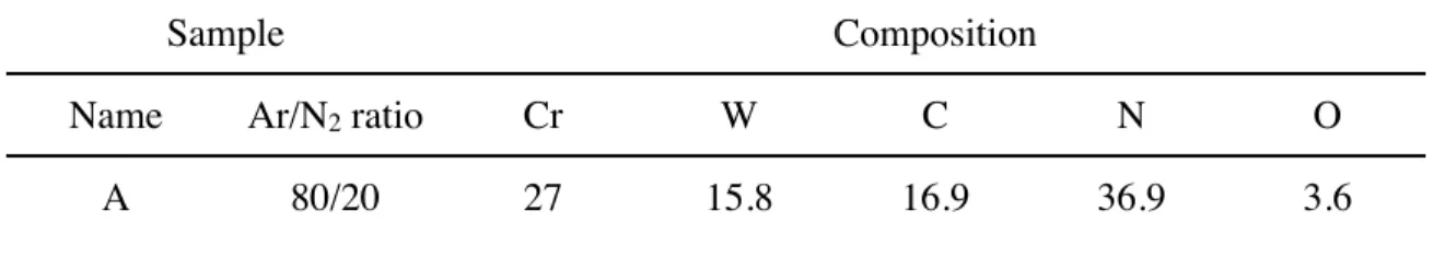
present is below the detection limits (~ 0.1 at %) of the analysis system. For the CrWCN samples, the atomic concentrations are summarized in Table 1.
Table 1. Summary of the EDS results for CrWCN sample prepared in different gas environments. Sample
Sample CompositionCompositionCompositionCompositionComposition
Name Ar/N2 ratio Cr W C N O
B 60/40 22.5 16.6 14.4 38.7 7.2
C 40/60 25.4 11.9 9.2 48.3 5.3
The target metal ratio for all three samples was 2:1. However, the actual ratios for Cr:W are 1.71, 1.36, and 2.13 for the samples deposited in Ar/N2 ratios of 80/20, 60/40, and 40/60,
respectively. There may be several factors at work. For example, CrN formation is more energetically favorable over WCN. In addition, the addition of N2 will more strongly affect the
WC sputtering rate. While there is no clear trend for the Cr:W ratio, there is a clear trend with regards to the incorporation of N2 into the coatings. As N2 concentration increased, the films
incorporated more N2 into the structure. While assuming most of this is bound as a nitride, the
EDS results indicate a significant amount of free N2 may be present. This gas may be trapped in
grain boundaries and voids created during deposition. B. Surface morphology
The surfaces of samples are shown in the secondary electron and AFM images of Fig. 1 (a)-(c). For the most part, the surfaces are relatively clean. However, there are few large spherical drops on each surface. These are more than likely areas of overgrowth due to defects/ contaminates on the Si substrate surface, such as dust particles. Neither the SEM nor SFM images show any significant differences between the films at this scale.
Figure 1. Secondary electron and AFM (insets) images of the CrWCN samples produced in an Ar/N2 environment of (a) 80/20, (b) 60/40, and (c) 40/60.
In Fig. 2, the roughness is plotted versus the N2 concentration. There is a clear trend to a reduced
surface roughness with increased N2 concentration.
Figure 2. Roughness parameter as a function of N2 concentration.
C. Structural Analysis
The structures of the three samples was studied with XRD. The peak parameters were determined with the CMPR program [33].
Figure 3. X-ray diffractogram for CrWCN samples. Depositions were carried out in an Ar/N2
environment with ratios of (a) 80/20, (b) 60/40, and (c) 40/60. Note the change in preferred orientation from (200) to (111) with decreasing N2 content.
Sample A, Fig. 3(a), has peaks at 36.9º, 42.7º and 62.3º representing the (111), (200), and (220) orientations. The preferred orientation is (200), with a lattice parameter of (0.42 ± 0.01) nm. In sample B, Fig. 3(b), the same orientations are present at 36.9º, 42.8º, and 62.5º, respectively, with no observed change in the lattice parameter. However, there is a change in the preferred orientation from (200) to (111). When the nitrogen content is further increased (as in sample C, Fig. 3(c)), this preference remains. In addition, the (111), (200), and (220) peaks shift to higher diffraction angles; this reduces the lattice parameter to (0.417 ± 0.001) nm. Additionally, these patterns are typical of the B1 (NaCl) structure [34-36].
By fitting the various peaks, the FWHM of each peak can be accurately determined. With this information, the the Debye-Scherrer equation is used to estimate the average crystallite size,
where λ is the x-ray wavelength, K is a shape factor (assumed to be 0.94, due to predominately cubic crystal shape), βsample is the FWHM (in radians) of the sample peak (preferred orientation),
βSi is the instrument broadening contribution, and θ is the preferred peak location (in radians).
From fitting, the (200) peak of sample A has a FWHM of 1.15º. The (111) peak of sample B has a FWHM of 0.91º, and the (111) peak of sample C yields a FWHM of 0.97º. The instrumental broadening is 0.31º. Inserting these numbers into the Equation 1, the average crystallite size of sample A is (8.56 ± 0.02) nm, sample B is (10.9 ± 0.2) nm, and sample C is (10.1 ± 0.2) nm. There are differences in the average crystallite size, but the only correlation is oxygen contamination. According to the EDS results, sample B is the most contaminated, followed by sample C and finally, by sample A. There are differences in the average crystallite size, but these variations are small to be statistically important. While the crystallite size follows somewhat the level of oxygen contamination in the film, the role of the impurities in the film growth in not obvious in this case.
D. Stress Measurements
From the linear regression of the measured dark fringe interference rings, the radius of curvature were calculated for each Si sample. This value was placed into a modified Stoney’s equation,
Equation 2
where ts is the substrate thickness, ts is the film thickness, R is the radius of curvature, and the
(s11+s12)-1 factor accounts for the elastic anisotropy of Si. From optical profilometry, the coatings
were approximately 2.5 µm thick. The estimated stress in the samples is compressive, with values of -(0.14 ± 0.06) GPa, -(0.32 ± 0.13) GPa, and -(0.13 ± 0.05) GPa for samples A, B, and C, respectively. There is no regular pattern to the stress with regards to N2 partial pressure, but
there is a correlation with WC content. Sample B has more WC present than either sample A or sample C. Reduced WC and increased Cr content seems to play a role in reducing the average stress of the coating.
E. Nanoindentation
Nanoindentation is a very powerful tool to elicit the mechanical properties of thin film coatings. Specifically, the hardness and Young’s modulus of each coating can be extracted from the loading-unloading curves, Fig. 4(a).
Figure 4. (a) The loading-unloading curve of sample C. The (b) hardness and (c) Young’s modulus of the CrWCN samples. To avoid substrate effects, the values are taken at an indentation depth of 100 nm (dashed line).
As shown in Fig. 4(b), the apparent hardness values are 15.4 GPa, 14.2 GPa, and 8.9 GPa for sample A, B, and C, respectively. Similarly, in Fig. 4(c), the calculated Young’s moduli are 232 GPa, 221 GPa, and 168 GPa, for samples A, B, and C, respectively. There may be a correlation between the composition and the mechanical properties. While there is no correlation with the N2 partial pressure, a relationship seems to exist between the mechanical properties and WC concentration. Increased amounts of WC appear to increase both the hardness and modulus of the sample.
However, these numbers are lower than a previously reported study of this system [37]. This is probably due to a combination of low stress, microporosity, substrate effects, and oxygen contamination in the current samples. In many materials, high stress states will magnify the
elastic response of the material [38]. Another factor is the addition of Cr. Cr tends towards columnar grain growth. This may induce voids and trap N2. For example, ceramic coatings with
only 10 % porosity show 2-3x lower hardness than their nonporous counterparts [39,40]. And while the hardness and Young’s modulus were evaluated at an indentation depth of 100 nm, far less than the standard 10 % of film thickness, there may be substrate effects [41]. In addition, there are O2 impurities. While there is no correlation in the spread of the values with the O2
contamination, other systems are known to suffer with this type of impurity [42,43]. IV. CONCLUSION
CrWCN samples were successfully prepared with RF magnetron sputtering. From optical profilometry, the coating thicknesses were estimated at 5 µm. From the diffraction data, the samples may be a solid solution with a B1 NaCl fcc structure, or a possible nanocomposite. In either case, the average unit cell is 0.42 nm for samples A and B, and 0.417 nm for sample C. While there is no significant deviation in the lattice parameters, there is variation in the average crystallite size. This appears to correlate with the level of O2 contamination. In addition, the
combination of this contamination with low stress, porosity, and possible substrate effects may be factors in the reported hardness values.
However, these films are adherent, with low surface roughness. These properties may lead to a variety of industrial uses. Future work will further evaluate the wear and tribological properties of these films. Future depositions of the CrWCN system will seek to minimize this contamination, and produce optimized coatings for industrial use.
ACKNOWLEDGMENTS
The authors would like to thank Romaric Masset for fabricating the steel substrates. This work was supported by the U.S. National Science Foundation (DMR-0806521) and the Regional Council of Burgundy, France.
REFERENCES
[1] A. Warren, A. Nylund and I. Olefjord, "Oxidation of tungsten and tungsten carbide in dry and humid atmospheres", Int. J. Refract. Met. Hard Mater., 14, 345, 1996.
[2] Y. Li, Y. Gao, B. Xiao, T. Min, Z. Fan, S. Ma and L. Xu, "Theoretical study on the stability, elasticity, hardness and electronic structures of WC binary compounds", J. Alloys Compd., 502, 28, 2010.
[3] W. Acchar, U.U. Gomes, W.A. Kaysser and J. Goring, "Strength Degradation of a Tungsten Carbide-Cobalt Composite at Elevated Temperatures", Mater. Charact., 43, 27, 1999.
[4] R.I. Blombery, C.M. Perrot and P.M. Robinson, "Abrasive wear of tungsten carbide-cobalt composites. I. Wear mechanisms", Mater. Sci. Eng., 13, 93, 1974.
[5] J.A. Bailey, A.-M. Bayoumi and J.S. Stewart, "Wear of some cemented tungsten carbide tools in machining oak", Wear, 85, 69, 1983.
[6] A.J. Gant and M.G. Gee, "Wear of tungsten carbide-cobalt hardmetals and hot isostatically pressed high speed steels under dry abrasive conditions", Wear, 251, 908, 2001.
[7] J.S. Becker and R.G. Gordon, "Diffusion barrier properties of tungsten nitride films grown by atomic layer deposition from ", Appl. Phys. Lett., 82, 2239, 2003.
[8] C. Shi, X.F. Yang, A.M. Zhu and C.T. Au, "Catalytic activities of tungsten nitride for NO dissociation and reduction with hydrogen", Catal. Today, 93, 819, 2004.
[9] T. Polcar, N.M.G. Parreira and A. Cavaleiro, "Structural and tribological characterization of tungsten nitride coatings at elevated temperature", Wear, 265, 319, 2008.
[10] C.S. Lin, C.S. Ke and H. Peng, "Corrosion of CrN and CrN/TiN coated heat-resistant steels in molten A356 aluminum alloy", Surf. Coat. Technol., 146, 168, 2001.
[11] I.E. Paulauskas, M.P. Brady, H.M. Meyer III, R.A. Buchanan and L.R. Walker, "Corrosion behavior of CrN, Cr2N and [pi] phase surfaces on nitrided Ni-50Cr for proton exchange
membrane fuel cell bipolar plates", Corros. Sci, 48, 3157, 2006.
[12] T. Hurkmans, D.B. Lewis, J.S. Brooks and W.D. Münz, "Chromium nitride coatings grown by unbalanced magnetron (UBM) and combined arc/unbalanced magnetron (ABS (TM))
deposition techniques", Surf. Coat. Technol., 86, 192, 1996.
[13] G. Bertrand, C. Savall and C. Meunier, "Properties of reactively RF magnetron-sputtered chromium nitride coatings", Surf. Coat. Technol., 96, 323, 1997.
[14] S. Han, J.H. Lin, J.J. Kuo, J.L. He and H.C. Shih, "The cavitation-erosion phenomenon of chromium nitride coatings deposited using cathodic arc plasma deposition on steel", Surf. Coat. Technol., 161, 20, 2002.
[15] P. Hones, N. Martin, M. Regula and F. Levy, "Structural and mechanical properties of chromium nitride, molybdenum nitride, and tungsten nitride thin films", J. Phys. D-Appl. Phys., 36, 1023, 2003.
[16] W. Brandl and C. Gendig, "Corrosion behaviour of hybrid coatings", Thin Solid Films, 290, 343, 1996
[17] J. Creus, H. Idrissi, H. Mazille, F. Sanchette and P. Jacquot, "Improvement of the corrosion resistance of CrN coated steel by an interlayer", Surf. Coat. Technol., 107, 183, 1998.
[18] S. Han, J.H. Lin, S.H. Tsai, S.C. Chung, D.Y. Wang, F.H. Lu and H.C. Shih, "Corrosion and tribological studies of chromium nitride coated on steel with an interlayer of electroplated chromium", Surf. Coat. Technol., 133, 460, 2000.
[19] H.C. Barshilia, N. Selvakumar, B. Deepthi and K.S. Rajam, "A comparative study of reactive direct current magnetron sputtered CrAlN and CrN coatings", Surf. Coat. Technol., 201, 2193, 2006.
[20] F.B. Wu, S.K. Tien, J.G. Duh and J.W. Lee, "Microstructure evaluation and mechanical properties of nanolayered chromium nitride/tungsten nitride coating", J. Electron. Mater., 34, 1533, 2005.
[21] J. Musil, "Hard and superhard nanocomposite coatings", Surf. Coat. Technol.,125, 322, 2000.
[22] S. Veprek, A. Niederhofer, K. Moto, T. Bolom, H.D. Männling, P. Nesladek, G. Dollinger and A. Bergmaier, "Composition, nanostructure and origin of the ultrahardness in nc-TiN/a-Si3N4/a-and nc-TiSi2 nanocomposites with HV = 80 to ≥ 105 GPa", Surf. Coat. Technol., 133, 152, 2000.
[23] S. Veprek and S. Reiprich, "A concept for the design of novel superhard coatings", Thin Solid Films, 268, 64, 1995.
[24] V.V. Brazhkin, A.G. Lyapin and R.J. Hemley, "Harder than diamond: dreams and reality", Philos. Mag. A, 82, 231, 2002.
[25] S. Veprek, M.G.J. Veprek-Heijman, P. Karvankova and J. Prochazka, "Different approaches to superhard coatings and nanocomposites", Thin Solid Films, 476, 1, 2005.
[26] S. Veprek, A.S. Argon and R.F. Zhang, "Design of ultrahard materials: Go nano!", Philos. Mag., 90, 4101, 2010.
[27] A.A. Voevodin, S.V. Prasad and J.S. Zabinski, "Nanocrystalline carbide/amorphous carbon composites", J. Appl. Phys., 82, 855, 1997.
[28] A.A. Voevodin, J.P. O'Neill and J.S. Zabinski, "Tribological performance and tribochemistry of nanocrystalline WC/amorphous diamond-like carbon composites", Thin Solid Films, 342, 194, 1999.
[29] ICDD, Powder Diffraction File (Database), edited by S. Kabekkodu, International Centre for Diffraction Data, 2007.
[30] G. Janssen, "Stress and strain in polycrystalline thin films", Thin Solid Films, 515, 6654, 2007.
[31] W.C. Oliver and G.M. Pharr, "Improved technique for determining hardness and elastic modulus using load and displacement sensing indentation experiments", J. Mater. Res., 7, 1564, 1992.
[32] X. Chen and J.J. Vlassak, "Numerical study on the measurement of thin film mechanical properties by means of nanoindentation", J. Mater. Res., 16, 2974, 2001.
[33] B.H. Toby, "CMPR- a powder diffraction toolkit", J. Appl. Crystallogr., 38, 1041, 2005. [34] P. Hones, R. Consiglio, N. Randall and F. Lvy, "Mechanical properties of hard chromium tungsten nitride coatings", Surf. Coat. Technol., 125, 179, 2000.
[35] A. Lousa, J. Romero, E. Martinez, J. Esteve, F. Montal\=a and L. Carreras, "Multilayered chromium/chromium nitride coatings for use in pressure die-casting", Surf. Coat. Technol., 146, 268, 2001.
[36] B.S. Yau, C.W. Chu, D. Lin, W. Lee, J.G. Duh and C.H. Lin, "Tungsten doped chromium nitride coatings", Thin Solid Films, 516, 1877, 2008.
[37] M.J. Walock, I. Rahil, Y. Zou, L. Imhoff, S.A. Catledge, C. Nouveau and A.V. Stanishevsky, "Sputtered tungsten-based ternary and quaternary layers for nanocrystalline diamond
deposition", J. Nanosci. Nanotechnol., submitted
[38] C. Lu, Y.W. Mai and Y.G. Shen, "Recent advances on understanding the origin of superhardness in nanocomposite coatings: A critical review", J. Mater. Sci., 41, 937, 2006. [39] J. Luo and R. Stevens, "Porosity-dependence of elastic moduli and hardness of 3Y-TZP ceramics", Ceram. Int., 25, 281, 1999.
[40] Y.V. Milman, S.I. Chugunova, I.V. Goncharova, T. Chudoba, W. Lojkowski and W. Gooch, "Temperature dependence of hardness in silicon-carbide ceramics with different porosity", Int. J. Refract. Met. Hard Mater., 17, 361, 1999.
[41] J.L. He and S. Veprek, "Finite element modeling of indentation into superhard coatings", Surf. Coat. Technol., 163, 374, 2003.
[42] S. Veprek, H.D. Männling, A. Niederhofer, D. Ma and S. Mukherjee, "Degradation of superhard nanocomposites by built-in impurities", J. Vac. Sci. Technol B: Microelectron. Nanometer Struct, 22, L5, 2004.
[43] S. Hao, B. Delley, S. Veprek and C. Stampfl, "Superhard nitride-based nanocomposites: role of interfaces and effect of impurities", Phys. Rev. Lett., 97, 86102, 2006.