Science Arts & Métiers (SAM)
is an open access repository that collects the work of Arts et Métiers Institute of
Technology researchers and makes it freely available over the web where possible.
This is an author-deposited version published in: https://sam.ensam.eu Handle ID: .http://hdl.handle.net/10985/14917
To cite this version :
Mathieu DURAND, Corentin LOTHODE, Frédéric HAUVILLE, Alban LEROYER, Michel
VISONNEAU, Ronan FLOCH, L GUILLAUME - FSI Investigation on Stability of Downwind Sails with an Automatic Dynamic Trimming - In: The Third International Conference on Innovation in High Performance Sailing Yachts, INNOVSAIL, Lorient, France, France, 2013-06 - The Third International Conference on Innovation in High Performance Sailing Yachts, Lorient, France -2013
Any correspondence concerning this service should be sent to the repository Administrator : [email protected]
FSI Investigation on Stability of Downwind Sails with an Automatic Dynamic
Trimming
M. Durand, Company K-Epsilon, Sophia-Antipolis, France, [email protected]
C. Lothode, Company K-Epsilon, Sophia-Antipolis, France, [email protected]
F. Hauville, Research Institute of the French Naval Academy, France, [email protected]
A. Leroyer, Centrale Nantes/CNRS, France, [email protected]
M. Visonneau, Centrale Nantes/CNRS, France, [email protected]
R. Floch, Incidences-Sails, Brest, France, [email protected]
L. Guillaume, BSG-Développements, La Rochelle, France, [email protected]
Gennakers are lightweight and flexible sails, used for downwind sailing configurations. Qualities sought for this kind of sail are propulsive force and dynamic stability. To simulate accurately the flow around such a sail, several problems need to be solved. Firstly, the structural code has to take into account cloth behavior, orientation and reinforcements. Flexibility is obtained by modeling wrinkles. Secondly, the fluid code needs to reproduce the atmospheric boundary layer as an input boundary condition, and be able to simulate separation. Thirdly, fluid-structure interaction (FSI) is strong due to the lightness and the flexibility of the structure. The added mass is three orders of magnitude greater than the mass of the sail, and large structural displacement occurs, which makes the coupling between the two solvers difficult to achieve. Finally, the problem is unsteady, and dynamic trimming is important to the simulation of spinnakers [4].
The main objective is to use numerical simulations to model spinnakers, in order to predict both propulsive force and sail dynamic stability. Recent developments [2] are used to solve these problems, using a finite element program dedicated to sails and rig simulations coupled with a RANSE solver. The FSI coupling is done through a quasi-monolithic method. An ALE formulation is used, hence the fluid mesh follows the structural deformation while keeping the same topology. The fluid mesh deformation is carried out with a fast, robust and parallelized method based on the propagation of the deformation state of the sail boundary fluid faces [3].
Tests are realized on a complete production chain: a sail designer from Incidences has designed two different shapes of an IMOCA60 spinnaker with the SailPack software. An automatic procedure was developed to transfer data from Sailpack to a structure input file taking into account the orientation of sailcloth and reinforcements. The same automatic procedure is used for both spinnakers, in order to compare dynamic stability and propulsion forces. Then a new method is developed to quantify the stability of a downwind sail.
1 INTRODUCTION
1.1 UNSTEADY FSI ON DOWNWIND SAILS
In recent years, CFD computations for sailing yachts and specifically for sails have increased considerably the performance of yachts sails. Most publications have concentrated on upwind sails. Downwind sails, due to their lightweight and instabilities are more frequently treated with experimental procedure (Renzsch [6]). A few publications try to simulate the complex flow and the response of the downwind structure [4] [7] [8]. To the author’s knowledge, no published numerical unsteady FSI on downwind sails is available.
1.2 GOALS OF DOWNWIND SAILS
Sail designers use specific software such as Sailpack to define the sail shape, called the moulded shape based on their experience to develop a flying shape. Sail designers try to optimize the parameters to maximize the propulsive force, while keeping the most stable flying spinnaker.
Stability is essential for gennakers, particularly for single-handed boats. Stability can be defined by sailmakers as the capability of the sail to maintain its trimmed shape. The leading edge of a trimmed gennaker is very light and has a periodic behavior. When the sail is breaking (i.e. curling) on the luff, a stable gennaker does not need to have the trim adjusted: it is unfolding on its own. In the case of an unstable gennaker, a crew member
must adjust the trim or bear away to unfold the gennaker. Unfortunately, this behavior is very sensitive to wind variations, and to the boat motions. There is no physical quantity that directly measures the stability of a gennaker: it is only indicated by the sailor’s feel.
Stability as a dynamic behavior, requires the use of a dynamic FSI tool to simulate. We have also developed a trimming procedure, in order to quantify the stability of the gennakers.
In this study, we investigate two real gennakers built, tested and used during the last Vendée Globe. Thus, the two spinnakers are really close in terms of their design, but have different performances. Those differences are small, but significant for both sailors and sailmakers. These two spinnakers have been digitized and then compared for one wind condition, taking into account the atmospheric boundary layer.
2 ARA WITH FINE
TM/Marine: A COMPLETE
UNSTEADY FSI SOFTWARE
Figure 1 : quasi-monolithic algorithm for fluid-structure interaction, fluid algorithm in blue, FSI
added procedure in red.
Modeling the wind, sail and rig interactions on a sailing yacht is a complex subject, because the quality of the simulation depends on the accuracy of both the structural and fluid simulations, which strongly interact. Moreover, the sails are subjected to highly unsteady oscillations due to waves, wind variations, course changes or trimming
for example, but sometimes also due to the unsteadiness of the flow itself (vortex shedding, unsteady separation location, etc). The problem for downwind sails is even more complex because the flow is often detached from the sails, and the sails are subject to large shape changes. IRENav, K-Epsilon and the DSPM team of LHEEA have jointly developed a coupled computational tool able to compute the fluid-structure interaction characterizing the dynamic behavior of sails in wind.
This coupled simulation tool is composed of an original finite element code ARA [2] developed by K-Epsilon to simulate sails and the rig of sailing boats (mast, shrouds, sheets, etc). A wrinkle formulation is included to model the local deformations of sails without having to use too many elements. This code is coupled to the URANSE solver ISIS-CFD [1] (internationally distributed by NUMECA Int. as FINE™/Marine) developed by the DSPM team of LHEEA.
The fluid-structure interaction between sails and wind is a difficult problem because it is strongly coupled. As stated previously, the added mass on a spinnaker is typically three orders of magnitude larger than the mass of the structure. Adding the fact that the structure has almost no bending stiffness, this makes it a very difficult problem. The followed approach is based on the use of an improved strongly-coupled methodology. The stability of the multi-step procedure is ensured by the use of the Jacobian matrix characterizing the coupling between the structure and the fluid; this Jacobian is approximated with the help of a potential fluid solver AVANTI, developed by K-Epsilon. Although not monolithic, this algorithm is very stable, fast and parallelized.
Figure 2 : Fluid mesh deformation around a main sail and gennaker, during an unsteady simulation.
A new mesh deformation tool has also been developed to transmit the deformation of the sails to the fluid domain without having to rebuild a new grid from scratch. This method, based on the combination of an explicit advancing front method and smoothing is also
parallelized, fast, robust and used to compute the large deformations of the unstructured mesh around multiple bodies like a spinnaker and main sail interacting together.
The code’s accuracy was verified by an experimental comparison performed on a well-controlled test case with an original experiment developed by IRENav [2] [9], which consisted of a square of spinnaker fabric mounted on two carbon battens which were moved in a forced oscillation. Finally, applied application is made on an unsteady sailing spinnaker with an automatic trimming algorithm, interacting with a mainsail which was realized to illustrate the potential of the present fluid-structure coupling (show Figure 2 for an example, from [2]).
3 CHOICE AND DESIGN OF THE TWO GENNAKERS
3.1 CHOICE
Shapes of gennakers are widely differing, depending of the type of boat, the range of wind and their use. In this paper, two very similar gennakers are compared, in order to estimate the capability of the process to distinguish the characteristics of closely related sails.
These sails were designed and used during the Vendée Globe 2012-2013 by two skippers.
3.2 DESIGN
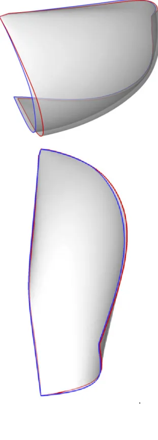
Once gennaker A was designed, Gennaker B was a small evolution with these differences:
- the luff twist is 1% smaller and the luff roach is 0.4% smaller
- the sail is 1% less twisted
- the maximum sail camber is 0.7% deeper, and 1% further forward
The sail areas are identical and the tack, head and clew points are in the same position for both spinnakers.
Figure 3 : Top view of the two spinnakers as moulded: Gennaker A in red, and gennaker B in blue. On the top
is the luff (leading edge), on the left is the leech (trailing edge).
3.3 TESTS IN REAL LIFE
The two sails were tested by sailmakers during full-size sessions in real conditions. During tests, and without measurement, sailors feel that propulsive forces of the two gennakers were close. The goal of the modifications made on the second spinnaker was to get more stability. In fact, during test session, the luff of gennaker A was sometimes curling hard, and collapsing. The crew therefore had to modify the trim or bear away. This means that they change drastically the heading of the boat, in order to increase the incidence on the sail. These modifications of the trim or boat heading decreased the performance of the boat.
The luff of gennaker B had a different behavior: The luff curled moderately, and most of the time, no actions were needed to uncurl the luff.
4 GENNAKERS DIGITALISATION
Sails were designed by another sailmaker soft from the company Incidences. The real sails were digitized, using the software Sailpack developed by BSG Développements, in order to respect the initial shape of the mould.
The design process is as follow: • Design of the sail mould in 3D • Definition of seam layouts • Definition of patche layouts
• Definition of the cloth properties, the doubled or tripled layers and the orientation of the cloth for each panel.
From this information, SailPack calculated the 2D panels that were used to build the real sail. Then a triangular mesh is generated for each 2D panel. The outline nodes of the meshes were connected to simulate the assembly of the sail. All the nodes were then moved to recompose the sail in 3D, keeping the 2D initial node distances. This way the resulting 3D mesh is based on the 2D panels that are used for the real assembly of the sail.
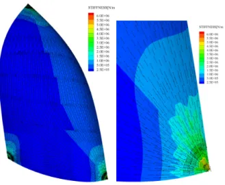
Stiffness matrices were associated to each mesh element. The cloth, its orientation and the number of layers were taken into account (Figure 4). Additional reinforcements were made with undeformable patches of 20 cm radius around the three points. The structural model was composed of about 7000 membrane elements, with 1 wire element for the sheet. The stiffness matrices of each material used were provided from tests on each piece of cloth. To simplify the computation, the mainsail and all rigging were not meshed, and were not simulated.
Figure 4 : Left: View of the stiffness of the gennaker. Right: zoom on the tack point. Arrays symbolize the
direction of maximal stiffness.
5 SIMULATION PROCESS
The steps of a computation can be summarized: - Structural computation
- Fluid meshing - Fluid computation
- Unsteady FSI with trimming procedure
5.1 STRUCTURAL COMPUTATION
In the first step, a structural computation is made with a uniform pressure on the sail. The length of the sheet is modified in order to orient the sail correctly according to the incoming flow. This first step permits the generation of the fluid domain.
5.2 FLUID MESHING
In the second step, the meshing around the deformed sail is done through HexpressTM, a fully hexahedral automated mesh generator based on the octree method. Boundaries are about 120m for the spinnaker in the two upwind directions, 240m in the two downwind directions, zmax is 120m and zmin is zero.
Cells are refined close to z=0m to take into account the atmospheric boundary layer, and refined near the sail. The entire model is meshed with 1.8 millions cells.
5.3 FLUID COMPUTATION
A fluid convergence is required before starting unsteady FSI simulation. Conditions on boundaries are made to simulate the atmospheric boundary layer. A boat speed of 5.92m/s is used in conjunction with a logarithmic boundary layer (Z0=0.002m); true wind speed measured at 30m is 7.72m/s, true wind angle is 150 degrees. The apparent wind speed at z= 15m is about 2.6m/s. The time
for an air particle to travel from the luff to the leech was 3.5s at z= 15m.
5.4 UNSTEADY FSI
The computations are realized on 2 dual-processor hexa-core Xeon X5670 (24 hexa-cores). The computation was restarted from the converged structure and converged fluid of the initial computations. The computation was performed with unsteady RANSE, with the k-omega SST turbulence model. The simulation time is fixed at 25 seconds. Such a long time is necessary in order to obtain periodic results.
5.5 TRIMMING PROCEDURE
The trimming algorithm (Figure 5) is defined in order to give an objective of zero pressure on the leading edge. This algorithm measures the pressure differential on the leading edge, and gives a trimming order such that the leading edge normal velocity is in opposition with the direction as the pressure force. A signal treatment with the leading edge velocity measurement is realized to obtain the sheet length. This procedure is dynamic: the length of the sheet is therefore always changing.
Figure 5 : The trimming algorithm.
Some tests were needed to adjust PID parameters: too violent of a trimming algorithm work like a “pumping” trimmer, some waves appears and move on the sail. With too slow of an algorithm, the luff collapses hard, and the computation could stop, due to limits of the mesh deformations.
6 RESULTS AND COMPARISONS BETWEEN THE TWO GENNAKERS
Figure 2 shows the result of the trimming algorithm for the two gennakers. During the first five seconds, the large amplitude proved that the gennaker is in a bad trim position at the start. The length of the sheet then slowly becomes periodic, and after 17s of simulation, it has become fully periodic.
Four periods of the periodic behavior of the two spinnaker are shown in Figure 6. The sheet lengths of the two gennakers are periodic, and very similar to the behavior of real life gennakers. Those sheet variations of gennaker A are much greater than those of gennaker B. Others results, reported in Table 1, Figure 9 and Figure
periods of the motion. Positions, as well as pressure and elongation have been averaged.
Figure 9 shows the delta pressure between pressure and suction faces of the sail. The trimming algorithm tries to obtain a zero pressure difference on the leading edge, this is accomplished for half of the luff: The upper half has a zero mean pressure difference. This is indicative of an attached flow on this part of the sail. In the lower part, where the luff is not curling, the low pressure on the leading edge indicates a detached flow.
Global pressure values are quite similar between the two sails, but gennaker B has a larger difference pressure.
Figure 6 : Result of trimming algorithm on the length of the two gennakers sheets (red line: gen. A, blue line:
gen. B): variations showing the instability of the gennakers.
From these results, we proposed a measurement of the stability, dependent of the triming algorithm, based on the height of the sail divide by the amplitude of the trimming:
Stab = H / Amp
Table 1 : Summary of the differences measured between the two gennakers.
Figure 7 : Top view and aft view of the averaged flying shape during computation.
.
Gennaker A Gennaker B Difference
Propulsive Force [N] 3625 3737 +3.1%
Side Force [N] 1555 1684 +8.3%
Vertical Force [N] 1223 1335 +9.2%
Figure 8 : Comparison of the behavior of the luff for the two gennakers during 4 steps of the period
Figure 9 : Two views of the averaged
(pressure - suction, [P]) during two period: gennaker A on the left, gennaker B on the right
Comparison of the behavior of the luff for during 4 steps of the period.
averaged delta pressure during two period: gennaker A on the left, gennaker B on the right.
Figure 10 : Front view of averaged
gennaker A. Yellow represent 0.4% of deformation in the cloth.
Sailmakers are also interested deformation of the cloth: Figure 1
deformation in the cloth. Maximum deformation 0.4% occurs near the luff, on both
reinforcements.
7 CONCLUSIONS
A complete procedure for the comparison of two gennakers was described. The procedure integrates CFD and FEA in a dynamic simulation with an automatic trimming procedure and is a powerful and
for the prediction of flying shape, as well as the sail forces and the stability of gennakers. A quantitative measure of the sail stability has been presented and gennaker B has been shown to be more stable with regards to this criteria.
Further investigations with this tool will be made, such as modification of the turbulence models for the fluid part, investigation of the influence of the mainsail in terms of the gennaker design and flying shapes. Other trimming procedures will be tested with the hel sailmakers and professional sailors.
made with an instrumented gennakers.
Front view of averaged deformation on ellow represent 0.4% of deformation in
the cloth.
Sailmakers are also interested in other results such as the
Figure 10 shows the mean the cloth. Maximum deformation of about near the luff, on both sides, near the
A complete procedure for the comparison of two gennakers was described. The procedure integrates CFD and FEA in a dynamic simulation with an automatic trimming procedure and is a powerful and advanced tool for the prediction of flying shape, as well as the sail forces and the stability of gennakers. A quantitative measure of the sail stability has been presented and gennaker B has been shown to be more stable with
tigations with this tool will be made, such as modification of the turbulence models for the fluid part, investigation of the influence of the mainsail in terms of the gennaker design and flying shapes. Other will be tested with the help of sailmakers and professional sailors. Comparisons will be made with an instrumented gennakers.
REFERENCES
[1] B. Augier, P. Bot, F. Hauville, and M. Durand, Experimental validation of unsteady models for
fluid structure interaction : Application to yacht sails and rigs, Journal of Wind Engineering
and Industrial Aerodynamics 101 (2012), 53–66.
[2] M. Durand, Interaction fluide-structure souple et légère, applications aux voiliers, Ph.D. thesis,
Ecole Centrale Nantes, 2012.
[3] M. Durand, F. Hauville, P. Bot, B. Augier, Y. Roux, A. Leroyer, and M. Visonneau. Unsteady numerical simulations of downwind sails. In the second international conference on innovation in high performance sailing yachts (INNOV’SAIL 2010) (2010), 57–64.
[4] K. Graf, H. Renzsch Investigations of Downwind Sails and integration into Sailing Yacht Design Processes 2nd High Performance Yacht Design Conference Auckland, 14-16 February, 2006
[5] J. Wackers, B. Koren, HC Raven, A. van der Ploeg, AR Starke, GB Deng, P. Queutey, M. Visonneau, T. Hino, and K. Ohashi, Free-surface viscous flow solution methods for ship hydrodynamics, Archives of Computational Methods in Engineering 18 (2011), no. 1, 1–41.
[6] H. Renzsch and K. Graf. An experimental validation case for fluid-structure-interaction simulations of downwind sails, Proceedings of the 21th Chesapeake Sailing Yacht Symposium, March 2011.
[7] D. Trimarchi, Analysis of downwind sail structures using non-linear shell finite elements, Ph.D. Thesis, University of Southampton, 2012
[8] M. Lombardi, Numerical simulation of a sailing boat: free surface, fluid-structure interaction and shape optimization, Ph.D. Thesis, Ecole polytechnique fédérale de Lausanne, 2012
[9] B. Augier, Experimental Studies of the Fluid Structure Interaction on Soft Surfaces: Application to Yacht Sails, Ph.D. Thesis, French Naval Academy Research Institute - IRENav, 2012
AUTHORS BIOGRAPHY
M. Durand holds the current position of R&D director at
K-Epsilon company. He is responsible for FSI developments and sails simulations. His previous experience includes a PhD in fluid dynamic in 2012, but also sailing experience as match-racing skippers (#40 in world ranking in 2011).
C. Lothode holds the current position of R&D engineer
at K-Epsilon company. He is responsible for FSI computations and development. His previous experience includes a M.Sc. in Applied Mathematics.
F. Hauville holds the current position of Associate
Professor at Naval academy Research Institute-IRENav. He is co-responsible of the Voil'Enav project which concerns activities in the field of fluid dynamics applied to sailing yachts. His current research interests includes, both by numerical and experimental approaches, problems of fluid structure interaction applied to the deformation of flexible surfaces and the hydrodynamic study of the forced moving foils applied to propulsion and marine current turbines. His previous experience includes a PhD in fluid dynamic in 1996.
A. Leroyer holds the current position of Associate
Professor at the LHEEA laboratory of Ecole Centrale Nantes. His research topics revolve around the numerical modelling of the incompressible isothemal flows around complex geometries and are more specifically focused on the methodologies to integrate new physical phenomena inside a Navier-Stokes solver, as the fluid-structure interaction and the numerical modelling of cavitation. He is part of the developer team of ISIS-CFD. His previous experience includes a PhD in fluid dynamics in 2004.
M. Visonneau born in France in 1957. He obtained the
Engineer's diploma in 1980 from Ecole Nationale Supérieure de Mécanique (now Centrale Nantes) and the diploma of Advanced Naval Architecture from ENSM in 1981. In 1985, he got a PhD of Fluid Dynamics and Heat Transfer of University of Nantes and entered the "Centre National de la Recherche Scientifique (CNRS)" as Research Scientist. He became the head of the CFD department of the Fluid Mechanics Laboratory (ECN) from 1995 to 2012. In 2001, he got the Research Habilitation Diploma and was promoted Research Director within CNRS in 2006. His main research topics are Computational Fluid Dynamics (CFD), Ship Hydrodynamics and Turbulence Modeling for high Re flows. In 1991, he got the 2nd Cray Prize for CFD and has been awarded 30th Georg Weinblum Memorial Lecturer (2007-2008) in 2007.
R. Floch holds the current position of Sail Designer at
Incidence Brest. He is responsible of the R&D coordination, and the sails design of Figaro Class, M34, and Open 60. His previous experience includes two Olympics preparations with 470 boats.
L. Guillaume holds the current position of R&D
engineer at BSG Développements company. He is responsible for the development of SailPack sail design software and other sail analysis software. His previous experience includes the development of sail vision and analysis systems for different America’s cup campaigns.