Science Arts & Métiers (SAM)
is an open access repository that collects the work of Arts et Métiers Institute of
Technology researchers and makes it freely available over the web where possible.
This is an author-deposited version published in: https://sam.ensam.eu Handle ID: .http://hdl.handle.net/10985/13804
To cite this version :
Mario BERMUDEZ GUZMAN, Ignacio GONZALEZ PRIETO, Federico BARRERO, Mario Javier DURAN, Xavier KESTELYN - Open-Phase Fault Operation of 5-Phase Induction Motor Drives using DTC Techniques - In: IECON 2015 - 41st Annual Conference of the IEEE Industrial Electronics Society, Japon, 2015-11 - IECON 2015 - 41st Annual Conference of the IEEE Industrial Electronics Society - 2015
Any correspondence concerning this service should be sent to the repository Administrator : archiveouverte@ensam.eu
Open-Phase Fault Operation of 5-Phase Induction
Motor Drives using DTC Techniques
M. Bermúdez, I. González–Prieto, F. Barrero
Dpto. de Ingeniería Electrónica Universidad de Sevilla
Sevilla, Spain fbarrero@us.es
M.J. Durán
Dpto. de Ingeniería Eléctrica Universidad de Málaga
Málaga, Spain mjduran@uma.es
X
. Kestelyn
L2EP
Arts et Métiers ParisTech Lille, France Xavier.Kestelyn@ensam.eu
Abstract—Direct torque control (DTC) is extensively used in
conventional three-phase drives as an alternative to field-oriented control methods. The standard DTC technique was originally designed to regulate two independent variables using hysteresis controllers. Recent works have extended the procedure for five-phase drives in healthy operation accounting for the additional degrees of freedom. Although one of the main advantages of multiphase machines is the ability to continue the operation in faulty conditions, the utility of DTC after the appearance of a fault has not been covered in the literature yet. This paper analyses the operation of a five-phase induction motor drive in faulty situation using a DTC controller. An open-phase fault condition is considered, and simulation results are provided to study the performance of the drive, comparing with the behavior during healthy state.
Keywords—Multiphase induction motor drives; Direct Torque Control (DTC); Open-phase fault operation.
I. INTRODUCTION
Multiphase machines have been recognized like an alternative to conventional three-phase ones due to their usefulness in a niche of applications where high overall system reliability and reduction in the total power per phase are required. This is the case in electric vehicles, railway tractions, all-electric ships, more-electric aircrafts or wind power generation systems, where the main research activity has been focused on in recent times [1–2]. Asymmetrical six-phase and symmetrical five-phase induction machines with sinusoidally distributed stator windings are the most frequently considered multiphase machines. These drives offer some interesting characteristics when compared to their three-phase counterparts, like better fault tolerance [2]. However, multiphase drives normally require complex control strategies to exploit their advantages and fulfill their potential [1–2].
High performance applications in multiphase drives are based on control methods extended from the three-phase drives’ case. The most common control strategy in the multiphase drive case is the Rotor-Flux Oriented Control (RFOC) method, based on multiple inner current control loops commanded by an outer speed controller [3]. However, alternatives to the traditional inner current controllers have been recently proposed based on predictive control methods [4–6]. Predictive techniques have been also explored with success for the torque control of symmetrical five-phase
induction machines, like the predictive torque control (PTC) [7]. The PTC method is a competitor of the DTC technique proposed in [8] and [9], where switching tables are used to obtain the stator voltage vector that drives a five-phase induction machine and hysteresis controllers are utilized to regulate the electrical torque and stator flux of the machine. Although stator voltages in the secondary planes are diminished to avoid the generation of non-torque stator current components and the performance at low-speed operation is improved, only healthy operation is studied. The fault-tolerant operation of the multiphase induction motor drive was not covered.
Among the different possibilities to exploit the additional degrees of freedom of a multiphase machine, the fault-tolerant capability with no extra hardware has been object of intense research in the last years [2]. The most common faulty case is the open-circuit fault [10–13] but the interest of DTC in managing the fault operation has not been analyzed yet. For this reason, this work will cover the utility of DTC in open-circuit post-fault control of the symmetrical five-phase induction machine. The paper is organized as follows. Section II summarizes the five-phase induction machine model during healthy and open-phase fault operation modes, which is used as the basis of the analysis. The DTC control method applied during the faulty operation of the five-phase induction machine is described in Section III, where the necessities of the controller to manage the open-phase post-fault situation are analyzed. Finally, Section IV presents some simulation results where the ability of the modified DTC method managing the post-fault operation of the multiphase drive is studied. The conclusions are provided in the last section.
II. FIVE-PHASE INDUCTION MOTOR DRIVE IN NORMAL AND OPEN-PHASE FAULT OPERATION
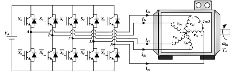
A five-phase induction machine with squirrel-cage rotor and symmetrically distributed stator winding (fixed spatial displacement ϑ=2π/5 between windings) is considered in this work. Fig. 1 shows a simplified scheme of the considered electromechanical system. The machine is modeled using a set of voltage equilibrium equations obtained from the stator and rotor electromagnetic circuits, where it is only considered the fundamental component coupling between stator and rotor circuits. The mutual leakage inductance between different phases, core losses or the magnetic saturation effect are also
ignored in the development of the model. Hence, the multiphase machine can be modelled with the following set of equations: ]) [ )] ( [ ] ]·[ ([ ] [ ] [ ] [ ] [ ] [ ] [ r sr s ss s s s s s s I L I L dt d I R dt d I R V ⋅ + + ⋅ = + ⋅ = θ λ (1) ]) [ )] ( [ ] ]·[ ([ ] [ ] [ ] [ ] [ ] [ ] [ s rs r rr r r r r r r I L I L dt d I R dt d I R V ⋅ + + ⋅ = + ⋅ = θ λ (2)
[
]
T es ds cs bs as s v v v v v V ]= [ (3)[
] [
T]
T er dr cr br ar r v v v v v V ] 0 0 0 0 0 [ = = (4)[
]
T es ds cs bs as s i i i i i I ]= [ (5)[
]
T er dr cr br ar r i i i i i I ]= [ (6)[
]
T es ds cs bs as s λ λ λ λ λ λ ]= [ (7)[
]
T er dr cr br ar r λ λ λ λ λ λ ]= [ (8)where v, i and λ denote the voltage, current and flux linkage, and the s and r subscripts stand for the stator and rotor variables, respectively. The a, b, c, d and e subscripts identify the five phases, and the T superscript designates the transpose operator.
The stator and rotor resistance and inductance matrices are defined as follows:
[ ]
5 · ] [Rs =Rs I (9)[ ]
5 · ] [Rr =Rr I (10)[ ]
·[
( )]
· ] [Lss =Lls I5 +M Λϑ (11)[ ]
·[
( )]
· ] [Lrr =Llr I5 +M Λϑ (12)[
( )]
·[
( )]
)] ( [Lsr θ = Lrs θ T =M ∆θ (13)
= t rdt 0 ω θ (14) = Λ 1 ) 4 cos( ) 3 cos( ) 2 cos( ) cos( ) cos( 1 ) 4 cos( ) 3 cos( ) 2 cos( ) 2 cos( ) cos( 1 ) 4 cos( ) 3 cos( ) 3 cos( ) 2 cos( ) cos( 1 ) 4 cos( ) 4 cos( ) 3 cos( ) 2 cos( ) cos( 1 )] ( [ ϑ ϑ ϑ ϑ ϑ ϑ ϑ ϑ ϑ ϑ ϑ ϑ ϑ ϑ ϑ ϑ ϑ ϑ ϑ ϑ ϑ (15) = ∆ ∆ ∆ ∆ ∆ ∆ ∆ ∆ ∆ ∆ ∆ ∆ ∆ ∆ ∆ ∆ ∆ ∆ ∆ ∆ ∆ ∆ ∆ ∆ ∆ ∆ ) 1 cos( ) 5 cos( ) 4 cos( ) 3 cos( ) 2 cos( ) 2 cos( ) 1 cos( ) 5 cos( ) 4 cos( ) 3 cos( ) 3 cos( ) 2 cos( ) 1 cos( ) 5 cos( ) 4 cos( ) 4 cos( ) 3 cos( ) 2 cos( ) 1 cos( ) 5 cos( ) 5 cos( ) 4 cos( ) 3 cos( ) 2 cos( ) 1 cos( )] ( [ θ (16)being [I5] the identity matrix of order 5, Rs and Rr the stator and
rotor resistance, respectively, M the mutual inductance, and Lls
and Llr the stator and rotor leakage inductance, respectively.
Finally, ∆k are angles defined as ∆k=θ+(k−1)ϑ, with
k={1,2,3,4,5}, where θ represents the instantaneous rotor azimuth with respect to the α-axis of the stationary reference frame and ωr is the rotor electrical speed.
Vdc ias ibs ids ics ies + -vbs vas + -+ vcs -ves -+ -vds + Sb Sb Sc Sc Sd Sd Se Se Sa Sa ωm Te n A B C D E ϑ=2π/5
Fig. 1. Schematic diagram of the five-phase drive.
Equation (17) is verified during the normal operation of the multiphase drive. Stator phase voltages can be obtained using the switching state of each leg of the power converter (Si), as it
is stated in (18) where Si = 0 if the lower switch is ON and Si =
1 if the opposite occurs. The power converter (a two-level five-phase voltage source inverter) provides 25=32 voltage vectors
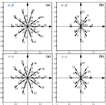
(30 active and 2 zero), which can be mapped applying the decoupling Clarke’s transformation defined in (19) in two orthogonal subspaces (α-β and x-y from now on) plus the zero-sequence component. Fig. 2(a) shows the available voltage vectors in the α-β and x-y subspaces. Each vector is identified using the decimal number corresponding to the binary code of the switching sate [Sa;Sb;Sc;Sd;Se].
es ds cs bs as v v v v v + + + + = 0 (17) − − − − − − − − − − − − − − − − − − − − = e d c b a dc es ds cs bs as S S S S S V v v v v v · 4 1 1 1 1 1 4 1 1 1 1 1 4 1 1 1 1 1 4 1 1 1 1 1 4 5 (18) = es ds cs bs as sz sy sx s s v v v v v v v v v v · 2 / 1 2 / 1 2 / 1 2 / 1 2 / 1 ) 3 sin( ) sin( ) 4 sin( ) 2 sin( 0 ) 3 cos( ) cos( ) 4 cos( ) 2 cos( 1 ) 4 sin( ) 3 sin( ) 2 sin( ) sin( 0 ) 4 cos( ) 3 cos( ) 2 cos( ) cos( 1 5 2 ϑ ϑ ϑ ϑ ϑ ϑ ϑ ϑ ϑ ϑ ϑ ϑ ϑ ϑ ϑ ϑ β α (19)
When one open-phase fault occurs, the machine becomes asymmetrical and the machine model needs to be reviewed because the sum of the healthy phase voltages is no longer zero. Since the five-phase machine is symmetrical, it will be considered further on that phase ‘a’ is the faulty phase without lack of generality. Hence, the induced back-emf of the phase ‘a’ is taken into account in the equilibrium phase voltage equations and the matrix that relates inverter and phase voltages in post-fault situation becomes:
+ − − − − − − − − − − − − − = 1 1 1 1 4 · 3 1 1 1 1 3 1 1 1 1 3 1 1 1 1 3 4 dt di L dt di L S S S S V v v v v r m s m e d c b dc es ds cs bs α α (20)
being the second term on the right hand side in (20) the back-emf of phase ‘a’, obtained from the neutral voltage evaluation [11–13], where Lm is defined as 5M/2. Notice that this term is
not considered to simplify the implementation of the DTC controller. Stator/rotor impedance asymmetries appear during
the fault operation that lead to non-circular trajectories of the stator currents in the α-β plane. To compensate these asymmetries, a modified Clarke’s transformation is proposed in [11], see equation (21), and a symmetrical post-fault model of the machine can be obtained with circular trajectories of the stator currents in the α-β plane. The proposed transformation generates the same set of equations in pre and post-fault conditions and in α-β-x-y coordinates. Then, the same model of the drive can be used in healthy and faulty operation, which simplifies the management of the faulty condition where the number of switching states is reduced from 25=32 to 24=16 and
the voltage vectors in α-β and x-y subspaces are consequently changed, Fig. 2(b). − − − − = es ds cs bs sz sy s s v v v v v v v v · 1 1 1 1 ) 8 sin( ) 6 sin( ) 4 sin( ) 2 sin( ) 4 sin( ) 3 sin( ) 2 sin( ) sin( 1 ) 4 cos( 1 ) 3 cos( 1 ) 2 cos( 1 ) cos( 5 2 ϑ ϑ ϑ ϑ ϑ ϑ ϑ ϑ ϑ ϑ ϑ ϑ β α (21)
III. OPEN-PHASE FAULT DTC CONTROLLER
The applied DTC technique is based on the method proposed in [8–9], where a two-level flux and a three-level torque hysteresis comparator are used to provide the control action. In addition, a low-speed region (speed lower than an established limit ωrth) is included in the control strategy to
mitigate neglected stator resistance effects. Fig. 3 summarizes this DTC control scheme. Ten active virtual voltage vectors are defined in the α-β subspace for the control purpose. Each one is applied depending on the electrical torque and flux estimators (sector identification block) and three hysteresis comparators. The virtual voltage vector is obtained combining a medium and a large size voltage vector in the α-β subspace with an adequate dwell time ratio to generate zero average volts-per-seconds in the x-y subspace. The selected voltage vectors in the α-β subspace must generate opposite in phase medium and small voltage vectors in the x-y subspace, so the normalized dwell times referred to a sampling period Ts are
Kv=(3− 5)/2 and (1–Kv), respectively, and the synthesized
virtual vectors have a magnitude of ((5− 5)/2)∙Vdc.
The extension of the control technique to the post-fault situation should be similar to the pre-fault case. However, the number of voltage vectors in α-β and x-y subspaces changes. Meanwhile 32 voltage vectors appear in the healthy operation only 16 are possible in the post-fault case, as it is illustrated in Fig. 2. Consequently, the virtual vectors defined in [8–9] are no longer available and new virtual voltage vectors must be defined to be used during the open-phase fault operation. However, the strategy to obtain zero average volts-per-seconds in the x-y subspace is no longer possible because α-β and x-y subspaces are no longer orthogonal when the fault appears. This is the consequence of losing one freedom degree during the open-phase operation of the drive, where a fixed relationship between α and x components establishes the following constraint: xs s i iα =− (22) -1 -0.5 0 0.5 1 -1 -0.8 -0.6 -0.4 -0.2 0 0.2 0.4 0.6 0.8 1 31 1 2 3 4 5 6 7 8 9 10 11 12 13 15 16 17 18 19 20 21 22 23 24 25 26 27 28 29 30 -1 -0.5 0 0.5 1 -1 -0.8 -0.6 -0.4 -0.2 0 0.2 0.4 0.6 0.8 1 31 1 2 3 4 5 6 7 8 9 10 11 12 13 14 15 16 17 18 19 20 21 22 23 24 25 26 27 28 29 30 - 1 -0.5 0 0.5 1 -1 -0.8 -0.6 -0.4 -0.2 0 0.2 0.4 0.6 0.8 0,15 1 2 3 4 5 6 7 8 9 10 11 12 13 14 - 1 - 0.5 0 0.5 1 -1 - 0.8 - 0.6 - 0.4 - 0.2 0 0.2 0.4 0.6 0.8 0,15 1 2 3 4 5 6 8 9 10 11 12 13 14 1 1 x–y x–y α–β α– β 0 0 (a) (b) 7 (a) (b) 14
Fig. 2. Available voltage vectors in the α-β (upper plots) and x-y (lower plots) planes in normal (a) and open-phase fault operation (b).
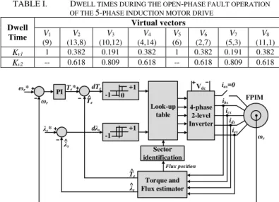
5-phase 2-level Inverter λ* FPIM ωr ias ibs ics ids ies Vdc ωr PI Sector identification T* ωrth ωr dT dω dλ +1 -1 Look-up table Torque and Flux estimator λ ^ T^ ωr* +1 -1 0 +1 -1 T^ Flux position λ ^
Fig. 3. DTC control scheme for symmetrical five-phase induction motor (FPIM) drives presented in [8] and [9]. The symbols ‘^’ and ‘*’ represent estimated and reference variables, respectively.
The persisting degree of freedom can be used to obtain zero average volts-per-seconds in the y direction from the remaining available voltage vectors. Following the proposed control strategy, which minimizes the y current component, eight active virtual voltage vectors (Vj) in the α-β subspace can be
defined as follows (see Fig. 4, where every Vj is placed in the
center of a sector limited using dashed lines and denoted with a circled number): 2 2 1 1 2 1, ) ( v v j v v vK v K V = + (23)
being Kv1 and Kv2 the dwell time ratios that define Vj from two
available voltage vectors (v1 and v2, respectively).
Different dwell time ratios are now required comparing with the normal operation of the drive (see Table I). The proposed post-fault DTC control scheme is detailed in Fig. 5. Comparing with the controller proposed in [9], the low speed region has not been considered during this study for the sake of simplicity (notice that the study will be based on simulation results and there is no need to include in the control strategy
the mitigation of the neglected stator resistance effects). The proposed post-fault DTC control scheme is then similar to the healthy DTC control method but using two hysteresis controllers and different virtual voltage vectors, as it is also shown in Fig. 5. Table II details the applied virtual voltage vectors, which depend on the dλs and dTe error signals, the
hysteresis controllers and the flux position. The torque reference (Te*) is obtained from a PI speed controller and the
stator flux reference (λs*) is fixed to the nominal one, like in the
healthy DTC case, because operation below the rated speed is also assumed. Notice that the stator flux and the electromechanical torque are estimated using their respective observers [8-9] and only four stator phase currents (ias = 0).
V1(9) V2(13,8) V8(11,1) V7(5,3) V4(4,14) V9(15) V5(6) V6(2,7) V3(10,12) V0(0) α-axis β-axis 2 3 4 5 6 7 8 1
Fig. 4. Applied virtual vectors in the α–β subspace using the proposed post-fault DTC control technique.
TABLE I. DWELL TIMES DURING THE OPEN-PHASE FAULT OPERATION OF THE 5-PHASE INDUCTION MOTOR DRIVE
Dwell Time Virtual vectors V1 (9) V2 (13,8) V3 (10,12) V4 (4,14) V5 (6) V6 (2,7) V7 (5,3) V8 (11,1) Kv1 1 0.382 0.191 0.382 1 0.382 0.191 0.382 Kv2 -- 0.618 0.809 0.618 -- 0.618 0.809 0.618 4-phase 2-level Inverter λs* FPIM ωr ias=0 ibs ics ids ies Vdc ωr PI Sector identification Te* dTe dλs Look-up table Torque and Flux estimator λs ^ ωr* +1 -1 0 +1 -1 T^e Flux position λs ^ T^e
Fig. 5. Proposed DTC control scheme in post-fault situation. The symbols ‘^’ and ‘*’ represent estimated and reference variables, respectively.
TABLE II. LOOK-UP TABLE FOR THE DTC CONTROLLER IN POST-FAULT SITUATION
dλs dTe Position of stator flux (Sector)
1 2 3 4 5 6 7 8 +1 +1 V2 V3 V4 V5 V6 V7 V8 V1 -1 V8 V1 V2 V3 V4 V5 V6 V7 0 V0 V9 V0 V9 V0 V9 V0 V9 -1 +1 V4 V5 V6 V7 V8 V1 V2 V3 -1 V6 V7 V8 V1 V2 V3 V4 V5 0 V9 V0 V9 V0 V9 V0 V9 V0
IV. POST-FAULT CONTROL PERFORMANCE
The proposed DTC method and the selected virtual voltage vectors have been tested using a Matlab/Simulink environment. The electrical and mechanical parameters of the multiphase induction machine are detailed in Table III and were obtained using different identification techniques [14–15]. Figs. 6 to 8 summarize the obtained results, where a DC link voltage (Vdc)
of 300 V was used and no load torque was applied. Notice also that the torque and flux hysteresis bands were programmed to be 1.06% and 1.29% of the rated values, respectively, the proportional and integral constants of the speed controller were adjusted using a trial and error procedure to be 2 and 20, respectively, and the control system was operated at a sampling frequency of 10 kHz.
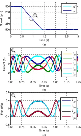
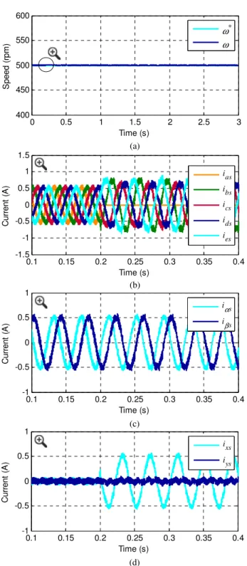
First, the steady-state performance during post-fault operation is studied. Fig. 6 summarizes the obtained results, where a reference speed of 500 rpm is assumed. The mechanical speed is successfully maintained in its reference value, Fig. 6(a), while the stator flux observer works properly and estimated stator flux values coincide with real ones, as can be seen in Fig. 6(c). Stator phase currents have a similar behavior to the one obtained using the minimum copper loss criterion during the post-fault operation of the drive [11, 13]. This criterion is focused on reducing the drive losses, ensuring proper torque/flux control and minimizing the non-torque contributing reference current. Then, electrical losses are minimized at the expense of unequal peaks of the phase currents, as it can be appreciated in Fig. 6(b). Notice also that the α-β stator current vector describes a circular trajectory using the DTC controller during the post-fault situation, being
ixs = -iαs and iys nearly null (see Fig. 6(d)).
A reversal test has been performed during the post-fault operation of the drive and the reference speed has been changed from 500 to –500 rpm. The obtained results are shown in Fig. 7, where it can be appreciated an adequate performance of the motor speed using the proposed DTC controller, Fig. 7(a). The typical waveforms in the α–β plane of the stator phase currents and the stator flux are obtained during the zero-crossing speed operating point, see Fig. 7(b) and Fig. 7(c), respectively.
The performance of the DTC controller when the fault appears is finally assessed. The speed reference is set to 500 rpm, as in previous tests. Fig. 8 summarizes the obtained comparative results from pre- to post-fault operation. The open-phase fault is simulated in phase ‘a’ at t = 0.2 s, and the fault detection delay is not considered during the test. Therefore, the transition between healthy and faulty models occurs as soon as the open-phase fault is generated. Fig. 8(a) shows the speed response, where it can be observed that the transition is done without any impact on the motor speed, being smoothly performed. Stator phase currents vary from healthy to faulty operation, as well as α-β stator currents, as it is plotted in Fig. 8(b) and Fig. 8(c), respectively. When the fault appears and thanks to the proposed control strategy, the x-component stator current becomes sinusoidal (ix = -iαs) while the
y-component stator current is nearly null, as it is observed in Fig. 8(d).
TABLE III. ELECTRICAL AND MECHANICAL PARAMETERS OF THE ANALYZED 5-PHASE IM
Parameter Value Units
Stator resistance, Rs 12.85 Ω
Rotor resistance, Rr 4.80 Ω
Stator leakage inductance, Lls 79.93 mH
Rotor leakage inductance, Llr 79.93 mH
Mutual inductance, M 681.7 mH
Moment of inertia, J 0.02 kg-m2
Number of pole pairs, P 3 --
Rated torque, Tn 4.70 N-m
Rated stator flux, λs* 0.389 Wb
(a) (b) (c) (d) 0 0.5 1 1.5 2 2.5 3 400 450 500 550 600 Time (s) S p e e d ( rp m ) ω* ω 1.3 1.35 1.4 1.45 1.5 1.55 1.6 -0.8 -0.4 0 0.4 0.8 Time (s) F lu x ( W b ) λαs λαs λβs λβs ^ ^ 1.3 1.35 1.4 1.45 1.5 1.55 1.6 -1.5 -1 -0.5 0 0.5 1 1.5 Time (s) C u rr e n t (A ) ias ibs ics ids ies -2 -1 0 1 2 -2 -1 0 1 2 iαs (A) i βs ( A ) -2 -1 0 1 2 -2 -1 0 1 2 ixs (A) iys ( A )
Fig. 6. Steady-state results in post-fault operation mode. The reference speed is settled at 500 rpm. (a) Speed response. (b) Zoomed-in stator phase currents. (c) Zoom-in of the reference and obtained stator flux waveforms. (d) Current trajectories in the α–β and x–y planes.
(a) (b) (c) 0 0.5 1 1.5 2 2.5 3 -500 -250 0 250 500 Time (s) S p e e d ( rp m ) ω* ω 0.65 0.75 0.85 0.95 1.05 1.15 1.25 -2 0 2 Time (s) C u rr e n t (A ) ias ibs ics ids ies 0.65 0.75 0.85 0.95 1.05 1.15 1.25 -0.8 -0.4 0 0.4 0.8 Time (s) F lu x ( W b ) λαs λαs λβs λβs ^ ^
Fig. 7. Reversal test during post-fault operation. A change in the reference speed from 500 to –500 rpm is applied. (a) Speed response. (b) Stator phase current and (c) stator flux waveforms in the α–β plane during the zero-crossing speed operating point.
From these preliminary results it can be concluded that the proposed DTC control strategy is a viable control alternative for symmetrical five-phase induction motor drives to field oriented or predictive control methods, not only during healthy operation of the drive but also if an open-phase fault appears. This conclusion extends the interest of DTC controllers in the multiphase drives’ field because it is stated for the first time their utility during the faulty operation of the system, although more simulation and experimental results must be obtained to analyze their comparative performance.
V. CONCLUSIONS
Multiphase induction machines are gaining increasing interest in industry applications due to their numerous advantages, like their fault tolerant capability. A lot of different control techniques have been recently developed in the multiphase drives’ field, most of them modified from similar methods previously used in conventional three-phase drives. As a result, DTC was recently proposed like an alternative control method in five-phase induction motor drives during the
(a) (b) (c) (d) 0.1 0.15 0.2 0.25 0.3 0.35 0.4 -1 -0.5 0 0.5 1 Time (s) C u rr e n t (A ) ixs iys 0.1 0.15 0.2 0.25 0.3 0.35 0.4 -1 -0.5 0 0.5 1 Time (s) C u rr e n t (A ) iαs iβs 0.1 0.15 0.2 0.25 0.3 0.35 0.4 -1.5 -1 -0.5 0 0.5 1 1.5 Time (s) C u rr e n t (A ) ias ibs ics ids ies 0 0.5 1 1.5 2 2.5 3 400 450 500 550 600 Time (s) S p e e d ( rp m ) ω* ω
Fig. 8. Transition from pre- to post-fault operation. The fault appears at t = 0.2 s. (a) Speed response. Zoomed-in (b) phase, (c) α–β and (d) x–y currents before (t < 0.2 s) and after (t > 0.2 s) the fault occurrence.
normal operation of the system. This paper extends the use of the DTC control technique from normal to open-phase fault operation of the drive. The obtained results analyze the performance of the controlled system in faulty operation, showing an adequate behavior and extending the interest of DTC controllers in the development of high-performance fault-tolerant five-phase induction motor drives.
ACKNOWLEDGMENT
The authors would like to thank the Junta de Andalucía and the Ministerio de Economía y Competitividad of the Spanish Government for their funding of this research under references P11-TEP-7555, DPI2013-44278-R, ENE2014-52536-C2-1-R.
REFERENCES
[1] E. Levi, “Advances in Converter Control and Innovative Exploitation of Additional Degrees of Freedom for Multiphase Machines,” accepted for publication at IEEE Trans. on Industrial Electronics.
[2] F. Barrero and M.J. Duran, “Recent Advances in the Design, Modeling and Control of Multiphase Machines,” accepted for publication at IEEE
Trans. on Industrial Electronics.
[3] Z. Libo, J.E. Fletcher, B.W. Williams and H. Xiangning,“Dual-plane vector control of a five-phase induction machine for an improved flux pattern,” IEEE Trans. on Industrial Electronics, vol. 55, no. 5, pp. 1996-2005, 2008.
[4] F. Barrero, M.R. Arahal, R. Gregor, S. Toral and M.J. Duran, “A proof of concept study of predictive current control for VSI driven asymmetrical dual three-phase AC machines,” IEEE Trans. on
Industrial Electronics, vol. 56, no. 6, pp. 1937-1954, 2009.
[5] M.J. Duran, J. Riveros, F. Barrero, H. Guzmán and J. Prieto, “Reduction of common-mode voltage in five-phase induction motor drives using predictive control techniques,” IEEE Trans. on Industry Applications, vol. 48, no. 6, pp. 2059-2067, 2012.
[6] C.S. Lim, E. Levi, M. Jones, N.A. Rahim and W.P. Hew, “FCS-MPC-based current control of a five-phase induction motor and its comparison with PI-PWM control,” IEEE Trans. on Industrial Electronics, vol. 61, no. 1, pp. 149-163, 2014.
[7] J.A. Riveros, F. Barrero, E. Levi, M. Duran, S. Toral and M. Jones, “Variable-speed five-phase induction motor drive based on predictive torque control,” IEEE Trans. on Industrial Electronics, vol. 60, no. 8, pp. 2957-2968, 2013.
[8] L. Zheng, J.E. Fletcher, B.W. Williams and X. He, “A novel direct torque control scheme for a sensorless 5-phase induction motor drive,”
IEEE Trans. on Industrial Electronics, vol. 58, no. 2, pp. 503-513, 2011.
[9] L. Gao, J.E. Fletcher and L. Zheng, “Low-speed control improvements for a 2-level 5-phase inverter-fed induction machine using classic direct torque control,” IEEE Trans. on Industrial Electronics, vol. 58, no. 7, pp. 2744-2754, 2011.
[10] A. Tani, M. Mengoni, L. Zarri, G. Serra and D. Casadei, “Control of multiphase induction motors with an odd number of phases under open-circuit phase faults,” IEEE Trans. on Power Electronics, vol. 27, no. 2, pp. 565-577, 2012
[11] H. Guzmán, M.J. Duran, F. Barrero, B. Bogado and S. Toral, “Speed control of five-phase induction motors with integrated open-phase fault operation using model-based predictive current control techniques,”
IEEE Trans. on Industrial Electronics, vol. 61, no. 9, pp. 4474-4484,
2014.
[12] H. Guzmán, F. Barrero and M.J. Duran, “IGBT-gating failure effect on a fault-tolerant predictive current controlled 5-phase induction motor drive,” IEEE Trans. on Industrial Electronics, DOI: 10.1109/TIE.2014.2331019.
[13] H. Guzmán, M.J. Durán, F. Barrero, B. Bogado, I. González and M.R. Arahal, “Comparative Study of Predictive and Resonant Controllers in Fault-Tolerant Five-phase Induction Motor Drives,” accepted for publication at IEEE Trans. on Industrial Electronics.
[14] A.G. Yepes, J.A. Riveros, J. Doval-Gandoy, F. Barrero, O. Lopez, B. Bogado, M. Jones and E. Levi, “Parameter identification of multiphase induction machines with distributed windings—Part 1: sinusoidal excitation methods,” IEEE Trans. on Energy Conversion, vol. 27, no. 4, pp. 1056-1066, 2012.
[15] J.A. Riveros, A.G. Yepes, F. Barrero, J. Doval-Gandoy, B. Bogado, O. Lopez, M. Jones and E. Levi, “Parameter identification of multiphase induction machines with distributed windings—Part 2: time-domain techniques,” IEEE Trans. on Energy Conversion, vol. 27, no. 4, pp. 1067-1077, 2012.