HAL Id: hal-01715084
https://hal.archives-ouvertes.fr/hal-01715084
Submitted on 15 Mar 2019
HAL is a multi-disciplinary open access
archive for the deposit and dissemination of
sci-entific research documents, whether they are
pub-lished or not. The documents may come from
teaching and research institutions in France or
abroad, or from public or private research centers.
L’archive ouverte pluridisciplinaire HAL, est
destinée au dépôt et à la diffusion de documents
scientifiques de niveau recherche, publiés ou non,
émanant des établissements d’enseignement et de
recherche français ou étrangers, des laboratoires
publics ou privés.
Influence of silicon content on the precipitation of
secondary carbides and fatigue properties of a 5%Cr
tempered martensitic steel
Denis Delagnes, Pascal Lamesle, M. H. Mathon, N Mebarki, Christophe
Levaillant
To cite this version:
Denis Delagnes, Pascal Lamesle, M. H. Mathon, N Mebarki, Christophe Levaillant. Influence of
silicon content on the precipitation of secondary carbides and fatigue properties of a 5%Cr
tem-pered martensitic steel. Materials Science and Engineering: A, Elsevier, 2005, 394 (1-2), pp.435-444.
�10.1016/j.msea.2004.11.050�. �hal-01715084�
Influence of silicon content on the precipitation of secondary
carbides and fatigue properties of a 5%Cr tempered
martensitic steel
D. Delagnes
a,b,∗, P. Lamesle
a, M.H. Mathon
c, N. Mebarki
a,b, C. Levaillant
aaEcole des Mines d’Albi Carmaux, Campus Jarlard, Route de Teillet, F-81013
Albi Cedex 09, France
bCentre d’Elaboration des Mat´eriaux et d’Etudes Structurales, CNRS, 29 rue Jeanne Marvig, BP 94347,
F-31055 Toulouse Cedex 4, France
cLaboratoire L´eon Brillouin (CEA-CNRS), CEA Saclay, F-91191 Gif-sur-Yvette, France
Abstract
In comparison with the conventional AISI H11 tool steel, which contains approximately 1 wt.% silicon, the modified steel AISI H11 (∼0.35 wt.% silicon) exhibits improved tensile and fatigue properties at 550 ◦C – the estimated tool surface temperature during the
high-pressure injection of aluminium alloys. The effect of silicon on the stability of secondary carbides was studied using transmission electron microscopy and small-angle neutron scattering. Silicon has a considerable influence on the precipitation of secondary carbides. A higher volume fraction and density of small particles were observed in the low-silicon-grade steel, both after heat treatment and after fatigue testing. The final discussion focuses on the influence of silicon in the precipitation sequence. It is concluded that silicon has a detrimental effect as it shifts the secondary hardening peak towards lower tempering temperatures.
Keywords: 5%Cr martensitic steel; Tempering; Secondary carbides; Isothermal fatigue; Silicon
1. Introduction
Martensitic steels containing 5%Cr were originally devel-oped for the die casting of aluminium alloys. AISI H11 steel is probably one of the most widely used among all the existing hot work die steels. Other typical applications include forg-ing dies, punches, mandrels, extrusion tools, etc. The main requirements after heat treatment are high strength and tough-ness to give a superior resistance to mechanical and thermal shocks and to the erosive action of molten aluminium[1]. Nevertheless, the fatigue resistance is not totally understood, as there is no clear correlation between fatigue and tensile properties. In fact, probably due to an unstable complex mi-crostructure containing a high density of tangled dislocations
∗Corresponding author. Tel.: +33 5 63 493248; fax: +33 5 63 493099.
E-mail address: [email protected] (D. Delagnes).
and secondary carbides, the slightest modification of compo-sition or heat treatment can have a huge impact on mechanical properties. This latter fact underpins continued research ac-tivities and offers several ways of improving the mechanical resistance of tempered martensitic steels. One of the most well-known way is the modification of the concentration of alloying elements directly involved in the precipitation of sec-ondary carbides, which shifts the secsec-ondary hardening peak towards higher temperatures. These alloying elements can be divided into two different categories depending on their ef-fect on precipitation: (a) carbide forming elements such as Mo, V, W, Nb, etc. and (b) elements only modifying the tem-pering kinetics such as Co, Si, etc. The effect of silicon on the tempering behaviour of steels has been widely investi-gated since the outstanding work by Owen[2]50 years ago. However, only limited information exists on alloyed steels tempered above the temperature of the secondary hardening
peak mainly induced by the intense precipitation of secondary carbides (hot work steels). The aim of the present work is to provide such information.
2. Experimental
2.1. Materials and heat treatment
The chemical compositions of the standard and the modi-fied AISI H11 steels are shown inTable 1. The silicon content of the modified steel (called LS for low silicon) was strongly reduced in comparison with that of standard steel (called HS for high silicon). Heat treatment includes austenitising at 980◦C for 1 h followed by air cooling, a first tempering at 550◦C for 2 h and finally a second tempering for 2 h at 625◦C for the HS grade and at 623◦C for the LS grade. The hardness obtained after heat treatment is close to 42HRC for the two grades.
2.2. Microstructural investigations
The microstructure of the specimens was investigated by transmission electron microscopy (TEM) and X-ray diffrac-tion (XRD). Observadiffrac-tions were performed using JEOL 2010 and Philips CM12 microscopes. The latter is equipped with an energy-dispersive X-ray analyser (EDX). Carbides were extracted from the martensitic matrix using the well-known replica technique in order to avoid contribution from the matrix to the chemical analysis. First, specimens were cut to small parallelepipeds (4 mm× 2 mm × 2 mm) and one side was polished with silicon carbide paper down to 2400 grit. The polished surface was lightly etched with 5 vol.% nital for 8 s before the deposition of a carbon coating of nearly 35 nm onto the etched surface. An extraction replica was then prepared by electrolytic etching in a so-lution of 10 vol.% hydrochloric acid in ethanol until the carbon film was detached and, after washing, collected on grids.
Selected area diffraction and EDX were performed in or-der to determine crystal structure and chemical composition of the carbides. The distribution of carbide sizes was ob-tained from TEM micrographs for nearly 600 particles per specimen. In order to evaluate the total weight fraction of carbides, a dissolution technique of the martensitic matrix was used. Carbides were extracted by an electrolytic method described in [3]. Crystallographic structure and chemi-cal composition analyses were performed using a Brucker
Table 1
Chemical composition (wt.%) of the standard and the modified AISI H11 steels
C Mn Si Cr Mo V Fe
Standard = HS 0.40 0.49 0.92 5.05 1.25 0.47 Balance Modified = LS 0.36 0.36 0.35 5.06 1.25 0.49 Balance
D5000 diffractometer equipped with a Cu K! radiation source and a graphite crystal monochromator and scintillation counter.
The neutron scattering experiments were performed at the Laboratoire L´eon Brillouin (CEA-CNRS), Saclay, on the PAXE small-angle instrument. The wavelength λ was 0.6 nm and the sample-to-detector distance (D) was 2 m, cov-ering a scattcov-ering vector (q) range from 0.3 to 1.6 nm−1 (q = 4π sin θ/λ, where 2θ is the scattering angle). Measure-ments were performed at room temperature, under a satu-rating magnetic field of H = 2 T perpendicular to the incident neutron beam direction, in order to separate the magnetic and nuclear scattering cross-sections.
The thickness (e) of samples for small-angle neutron scat-tering (SANS) experiments, pre-cut and mechanically pol-ished, is reduced between 0.5 and 1 mm. The measured transmission values (∼=97% for e = 0.5 mm and ∼=90% for
e = 1 mm) showed that multiple scattering corrections were
unnecessary.
The measured intensities were corrected using the stan-dard computer programs of the Laboratoire L´eon Brillouin for sample transmission, background intensity as well as de-tector response[4]. The analysis method has been reported elsewhere[5].
In the case of ferromagnetic materials, the SANS intensity is the result of two contributions, nuclear and magnetic, which depend, respectively, on the difference in composition and in magnetisation between the particles and the matrix. In terms of cross-section, the SANS intensity can be written as I(q)= 1
Vp
dΣ
dΩ(q)= fp[&ρ
2
nucl+ &ρ2magsin2α]
× F2(q, R)S(q, R), (1)
where I is the diffused intensity, Vp stands for the particle
volume, dΣ/dΩ the macroscopic differential cross-section,
fpthe precipitated volume fraction, and F(q, R) the form
fac-tor of the particle. F(q, R) includes a size distribution function
h(R), which is taken here as two symmetric normalised
Gaus-sian distributions. As the majority of small precipitates ob-served in TEM has a spherical shape (see the Section3.2.1), the particle form factor F(q, R) for spherical particles with a radius R was used. S(q, R) is the structure factor of the monodisperse hard-sphere model describing the interparticle interference effect, which is not negligible for a precipitated fraction larger than 0.01. This is calculated analytically by Ashcroft and Lekner[6] from the Percus–Yevick equation. &ρnucl,magare the nuclear and magnetic contrast terms given
by &ρnucl,mag= bpnucl,mag vpat − bmnucl,mag vmat , (2) where b is the nuclear or magnetic mean scattering length in the precipitates (p) or in the matrix (m), and vp,mat is the mean atomic volume either of the precipitates or the matrix. α is
the angle between the magnetisation of the sample and the scattering vector q.
As the magnetic moments lie parallel to the field H, the magnetic scattered intensity is zero in that direction and max-imum in the normal direction. Consequently, the nuclear cross-section can be measured at α = 0, while the sum of the nuclear and the magnetic cross-section is measured at α = π/2. Subsequently, the magnetic contrast can be calculated by a simple subtraction. Some information about chemical com-position can be deduced from the ratio between those two quantities, called ratio. For homogeneous particles, the A-ratio depends on the chemical composition, magnetisation and atomic density variations between precipitates and the matrix, and is given by
A= (dΣ/dΩ)⊥ ⃗H (dΣ/dΩ)∥ ⃗H =
&ρ2nucl+ &ρ2mag &ρ2nucl = 1 +
&ρ2mag &ρ2nucl.
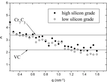
(3) The calculated A-ratio values for vanadium carbides (VC type) and chromium carbides (M7C3type) in the !-Fe matrix
are, respectively, equal to 2.2 and 3.4. Scattering lengths nec-essary to the calculation of the A-ratio were extracted from Ref.[7].
The relevant parameters obtained from the fitting of the relation(1)to the experimental data are:
- the factor J in the relation(1)independent of the size dis-tribution and containing the fraction of particles:
J= fp[&ρ2nucl+ &ρmag2 ] (4)
- the mean size of the particles (radius R);
- the full-width at the half-maximum of the Gaussian distri-bution.
An example of comparison between calculated and cor-rected experimental intensities as a function of q is shown inFig. 1. In spite of the different hypotheses formulated to
Fig. 1. Corrected intensities as a function of the scattering vector: compari-son between measured data and the calculated curve according to Eq.(1).
calculate the corrected intensities, the fit of the relation (1)
to the experimental data is reasonable for all the investigated specimens.
2.3. Isothermal fatigue testing
Total strain-controlled fatigue tests were carried out on a servohydraulic testing machine equipped with a resistance furnace. The axial strain was controlled and measured with a 10 mm gauge length extensometer. The waveform of the cycle was triangular at a frequency of 1 Hz, the mean strain being zero. Fatigue tests were per-formed at 550◦C, which is the surface tool temperature in high-pressure die casting operations [8], with total strain amplitudes lying between 0.7 and 2.0%. The specimen surface polishing was performed down to 1 "m diamond suspension.
3. Results
3.1. Tensile and fatigue properties
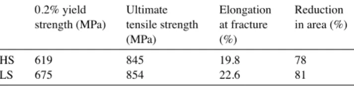
The tensile properties obtained at 550◦C are shown in
Table 2. Lowering the silicon content results in a noticeable increase in the 0.2% yield strength. This is an important me-chanical parameter as the stress calculated on the tool surface is inferior or close to the 0.2% yield strength depending on the considered zone on the die. The other properties are slightly improved (seeTable 2).
To compare the two steel grades, both fatigue behaviour and life duration were analysed. Concerning the cyclic load-ing, martensitic or bainitic steels have typical fatigue be-haviour: an overall significant softening till rupture[9–20]as shown inFig. 2. The stress amplitude versus number of cycles curve can be divided into two parts. A sharp softening is ob-served during the first few hundred cycles followed by a more gradual softening throughout the greater part of the lifetime. The dramatic decrease in the stress amplitude at the end of life is due to the propagation of one or several cracks in the speci-men gauge length. The cyclic softening is first associated with a strong decrease of the dislocation density generated during the quench as particularly shown in[20]and a subsequent modification of the dislocation structure. The second mech-anism involved in the softening is the coalescence of precip-itates[21–24]which also modifies the free slip distances of dislocations.
Table 2
Tensile properties obtained at 550◦C: comparison between the high silicon
and low silicon grades 0.2% yield strength (MPa) Ultimate tensile strength (MPa) Elongation at fracture (%) Reduction in area (%) HS 619 845 19.8 78 LS 675 854 22.6 81
Fig. 2. Evolution of the stress amplitude according to the number of cycles showing the significant softening of martensitic steels (&εt= 1%).
The softening amplitude, D, is defined by
D = ! &σ 2 " N=1 − ! &σ2 " N=Nf/2 , (5)
where N is the number of cycles, Nfthe number of cycles to
failure and &σ/2 the stress amplitude.Fig. 3shows that there is no significant difference between the two grades.
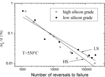
Both the Manson-Coffin and Basquin laws rationalise the fatigue lifetime. When results are plotted in a Manson-Coffin diagram (see Eq. (6)), fatigue lifetimes of both grades are similar, as shown inFig. 4 [21]. However, when the lifetime increases, the plastic strain amplitude tends to 0 and the mea-surement is not possible with a conventional extensometer:
&εp
2 = ε′f(2Nf)
c, (6)
where &εp/2 is the plastic strain amplitude measured at
half-life, ε′fthe fatigue ductility coefficient and c the fatigue duc-tility exponent.
Fig. 3. Total softening amplitudes as a function of &εP/2 measured at Nf/2:
comparison between the two grades.
Fig. 4. Manson-Coffin plots obtained at 550◦C.
The results of endurance tests are better expressed as a plot of the stress range measured at half-life:
&σ
2 = C(Nf)
p (7)
where C and p are, respectively, the coefficient and the expo-nent of the Basquin law. When results are plotted in a Basquin diagram (seeFig. 5), the exponent p has the same value for the two grades and Basquin curves are parallel. Therefore, a life-time ratio LR between the two grades, which is independent of the stress range, can be estimated by
LRLS/HS=
! CHS
CLS
"1/p
. (8)
Fatigue lifetimes of the LS grade are nearly five times higher than those of the HS grade. Consequently, lowering the sil-icon content in the AISI H11 steel results in increasing the fatigue lifetime at 550◦C.
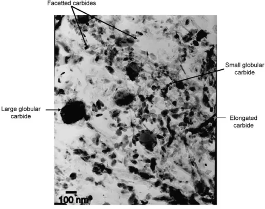
Fig. 6. Bright-field TEM image of the carbides extracted from the martensitic matrix (low silicon grade).
3.2. Secondary carbides 3.2.1. Sequence of precipitation
After heat treatment, four types of carbides were identified by diffraction patterns and EDX depending on their morphol-ogy (seeFig. 6). No significant differences were observed between the two grades:
(i) facetted carbides with a ratio length/width between 1 and 1.5: hexagonal CrFe carbides (M7C3type),
(ii) large globular carbides (100–300 nm): face-centred cu-bic CrFe carbides (M23C6type),
(iii) elongated carbides: orthorhombic FeCr carbides (M3C
type),
(iv) small globular carbides (<40 nm): face-centred cubic V carbides (MC type).
M stands for metallic elements.
XRD complementary results, only obtained for the LS grade, allow the determination of the sequence of precipi-tation.Fig. 7 shows the evolution of carbide compositions according to the heat treatment. The results can be sum-marised as follows: as-annealed steel contains M2C (M = Mo
mainly), M3C (M = Fe mainly), M23C6 (M = Fe and Cr
mainly) and a small fraction of MC (M = V mainly) car-bides. After quenching, only the vanadium carbide (MC) and small quantities of M3C and M23C6, probably not
dissolved during the austenitisation were found. After the first and the second tempering, X-ray analysis has shown the presence of MC, M3C, M7C3 and traces of M23C6
carbides.
The TEM characterisation of carbides prior to, and after tempering, confirms the precipitation of MC, M3C and M7C3
carbides during tempering in both grades. Therefore, MC and M7C3are unambiguously the main carbides involved in
the secondary hardening peak position and intensity visible on a diagram presenting tensile strength versus tempering temperature.
3.2.2. Precipitation of secondary carbides after the second tempering
For both investigated grades, two different populations of secondary carbides were identified by TEM after tempering:
Fig. 8. Bright-field TEM image of the first population of carbides (note that the large carbide in the bottom left hand corner is a M23C6 carbide not
dissolved during the austenitisation; low silicon grade).
(i) small carbides with an average size close to 6 nm. This first population shown in Fig. 8includes mainly vana-dium carbides and a significantly smaller quantity of chromium carbides. However, the determination of the morphology was not possible with high enough accuracy for precipitates smaller than 5 nm;
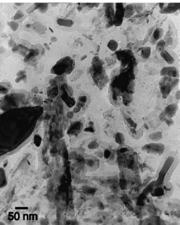
(ii) carbides with an average size in the range 20–40 nm as shown inFig. 9. This second population includes both chromium and vanadium carbides and a few iron car-bides.
Given a spherical shape, the size corresponds to the car-bide diameter. For facetted or elongated carcar-bides, the size is estimated by the addition of the apparent length and width divided by 2 (TEM observations on replicas).
The size distribution shown inFig. 10exhibits a bi-modal aspect. Clearly, the carbide quantity for the first population (smaller carbides) is significantly lower for the HS grade. Conversely, for the second population (larger carbides), the carbide quantity is much higher for the HS grade. In
addi-Fig. 9. Bright-field TEM image of the second population of carbides (low silicon grade).
tion, the average size of carbides including both populations is nearly 13 nm for the LS grade. This value should be com-pared with the mean size of 25 mm for the HS grade. The results obtained using SANS experiments are in good agree-ment with the main findings listed above (see theTable 3). The two populations were identified again. Nevertheless, the average size of the first population falls between 2 and 3 nm which is two or three times lower than the value obtained by TEM. This latter result is consistent with the fact that small carbides are probably not analysed by TEM and the distri-bution of size shown inFig. 10may largely deviate from the reality for the first three size intervals. In spite of the shape hy-pothesis (spherical instead of facetted carbides), the average size calculated by SANS is close to the estimation obtained by TEM for the second population.
The experimental value of the contrast ratio A as a function of the scattering vector is shown inFig. 11. For large scatter-ing vectors, A is very close to the value of 2.2 which corre-sponds to the theoretical value for the vanadium carbide VC. It means that small carbides are mainly vanadium carbides
Table 3
Comparison of the estimation of the average size of carbides obtained by SANS and by TEM (σ is the standard deviation of the Gaussian distribution)
SANS TEM
First population Second population First population Second population HS 2.6 nm/σ = 0.4 nm 33.5 nm/σ = 2.9 nm 6.1 nm/σ = 3.0 nm 28.8 nm/σ = 7.0 nm LS 2.3 nm/σ = 0.5 nm 36.5 nm/σ = 2.8 nm 6.6 nm/σ = 2.7 nm 33.1 nm/σ = 5.7 nm
Fig. 10. Size distribution of secondary carbides: comparison between the high silicon and low silicon grades.
which is also consistent with EDX analysis. Assuming that the first population contains only the vanadium carbides, the volume fraction of the first population can be estimated using the relationship(4). The volume fraction derived for the LS and HS grades are, respectively, 0.58 and 0.31%. These values should, however, be compared with the total volume fraction estimated by the dissolution method which is nearly 6.5% for both grades. The total volume fraction includes the two pop-ulations, interlath iron carbides and M23C6 carbides
undis-solved during austenitisation. However, only the first popula-tion is involved significantly in the strengthening mechanism as these fine intralath precipitates offer numerous pinning obstacles for the dislocations generated by quenching, thus preventing a quick rearrangement of the tangled dislocations. Consequently, the higher strengthening observed for the LS grade can be explained by a higher volume fraction of small intralath precipitates.
3.2.3. Influence of fatigue loading at 550◦C
Hot work die steels are generally simultaneously submit-ted to both elevasubmit-ted temperature and cyclic stress during
ser-Fig. 11. Experimental contrast ratio A vs. q: comparison with the theoretical values calculated for VC and Cr7C3carbides.
vice. It is therefore relevant to investigate to what extent mi-crostructural parameters are influenced by cyclic mechanical loading. TEM observations and SANS experiments were per-formed after a cyclic test at 550◦C with a total strain ampli-tude of 0.8 and 2%. Results are presented inTables 4 and 5. As shown inTable 5, an increase of the average size of carbides after a fatigue test is observed for both grades. As the duration of a fatigue test is quite short (less than 1 h for &εt= 2.0% including the heating time before starting the test)
and as the testing temperature is 70◦C below the tempering temperature, it can be concluded that coalescence is only induced by fatigue. Indeed, a third tempering treatment in the same time and temperature conditions as the fatigue test has no effect on the mechanical properties. Such dynamic ageing has already been observed in other tempered marten-sitic steels[22–25]. Two different mechanisms can explain the enhanced carbide coalescence during fatigue. The driving force for the dynamic coalescence of carbides is the mechan-ical energy that complements the thermal energy, which, on
Table 4
Estimation of the average size of carbides after a fatigue test at 550◦C
SANS TEM
First population Second population First population Second population &εt= 0.8% &εt= 2% &εt= 0.8% &εt= 2% &εt= 0.8% &εt= 2% &εt= 0.8% &εt= 2%
Carbide size (nm) HS 1.9 (0.4) 1.8 (0.4) 31.7 (2.6) 31.1 (3.1) Not observed 33.5 (8.5) 36.5 (9.6) LS 2.3 (0.6) 2.1 (0.6) 30.8 (2.6) 31.6 (2.7) 8.1 (3.6) 10.7 (3.3) 34.9 (9.1) 33.1 (8.2) σis the standard deviation of the Gaussian distribution and its values are given in parentheses.
Table 5
Influence of a fatigue test performed at 550◦C on the average size of carbides and the volume fraction of the small carbides
As heat-treated After fatigue &εt= 0.8% After fatigue &εt= 2%
Average size of carbides (nm) HS 25.0 33.5 36.5
LS 13.0 21.4 24.1
Volume fraction (%) of the 1st carbides population HS 0.31 0.18 0.06
Fig. 12. Carbon and silicon flux during the coarsening of the cementite.
its own, is not sufficient to provide coalescence. The second mechanism is associated with pipe diffusion along disloca-tions, which is strongly affected by high-temperature plas-ticity. This kinetic effect was precisely described by Eggeler
[22]for creep conditions.
The differences between the LC and HC grades after fa-tigue are summarised as follows:
- TEM observations show an increase in the average size of small carbides for the LS grade, whereas small carbides are no more found in the HS grade (seeTable 4).
- The fatigue test induces a decrease of the volume fraction of small carbides estimated by the relation(4). This effect is stronger for the HS grade (Table 5).
In conclusion, results indicate that secondary carbides co-alescence is clearly accelerated under fatigue at elevated tem-perature for both grades. After fatigue, a higher quantity of small carbides is revealed in the LS grade which is consistent with a better fatigue resistance.
4. Discussion: influence of silicon on the precipitation
Silicon in normal concentrations is not a carbide-forming element in tool steels. However, it is already well known that silicon inhibits the precipitation of cementite. As one of the mechanism of nucleation of alloy carbides is the in situ nucleation at pre-existing cementite particles (i.e. the nuclei are formed on the interfaces between cementite and ferrite and the carbon is provided by the cementite), the precipitation of chromium and vanadium carbides is strongly influenced by the cementite stability during the first tempering.
Considering a cementite platelet in a Widmanst¨atten array during the first tempering as shown inFig. 12, the coarsen-ing is strongly dependent on carbon diffusion from the su-persaturated ferrite towards cementite. As silicon has a very low solubility in cementite, silicon segregates at the inter-face carbide/supersaturated ferrite. Several authors[26–28]
have performed chemical analysis close to cementite precipi-tates showing the high concentration of silicon rejected from the carbide in ferritic, bainitic and martensitic steels. Conse-quently, there is a silicon flux in the opposite direction to that of carbon (seeFig. 12).
The silicon and carbon concentrations as a function of the distance from the interface are shown inFig. 13. During the growth of the cementite, the silicon concentration gradient is negative near the interface as the silicon is rejected from the
Fig. 13. Concentrations of carbon and silicon near the cementite/ferrite in-terface during the cementite coarsening and dissolution.
cementite. Conversely, the carbon concentration gradient is positive as the excess of carbon in the supersaturated ferrite allows the coarsening of the cementite. The kinetics is differ-ent as carbon (interstitial) diffuses much faster than silicon (substitutional). If the influences of all the alloying elements except silicon are neglected (i.e. a ternary alloy Fe Si C is considered), the carbon concentration gradient driving the growth of cementite is given by Fick’s first law:
JC = − D!-FeCC ∂CC ∂x − D !-Fe CSi ∂CSi ∂x , (9) where D!-FeCSi is the cross-diffusion coefficient[29].
The influence of silicon on the tempering character-istics of low-alloyed steels has been extensively studied
[2,26–28,30–36]. Even if discussions are still open[37], it is well established that silicon significantly delays the softening process of low-alloyed steels during tempering. There is con-siderable accumulated evidence that silicon reduces the flux of carbon required for the growth of cementite. This effect increases the strength of the steel at a fixed temperature since carbon remains in interstitial solid solution in the martensitic lattice or enables higher tempering temperatures to be used without severe loss in tensile strength. Consequently, the re-pulsive interaction between carbon and silicon in the marten-site bulk results in a positive cross-diffusion coefficient in Eq.(9). The situation is therefore similar to that observed in austenite as originally shown by Darken[38]. The subsequent mathematical framework for the diffusion in multicompo-nent metallic solid solution was developed by Kirkaldy[39]. Due to experimental difficulties, thermodynamic data are not available for supersaturated ferrite. In addition, there is very little information on the influence of silicon on the tempering process at higher temperatures in steels containing sufficient carbide-forming elements to induce a secondary hardening peak above 500◦C.
Depending on the nucleation mechanism of alloyed car-bides, the influence of silicon is summarised as follows:
(i) For in situ nucleation at pre-existing cementite parti-cles, carbon is provided by the adjacent cementite which
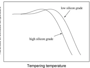
Fig. 14. Qualitative influence of silicon content on the secondary hardening peak.
gradually dissolves.Fig. 13 shows the carbon and sil-icon concentrations as a function of the distance from the interface during the cementite dissolution. Accord-ing to Fick’s first law and since D!-FeCSi >0, the sil-icon gradient near the interface induces an increase of the flux of carbon in the x > 0 direction acceler-ating the dissolution of cementite. Subsequent inten-sive precipitation of alloy carbides occurs and the sec-ondary hardening peak tends to be shifted towards lower temperatures.
(ii) For separate nucleation within the martensitic matrix, the effect of silicon is a delay in the coarsening of Fe3C to
such an extent that more carbon is available to form a finer carbide dispersion at lower temperatures just as in the previous case (i).
Consequently, the main benefits of the silicon addition seen in low-alloyed steels with high tensile strength[30,32]
are obviously no longer observed in hot-work tool steels as the secondary hardening peak is shifted towards lower tem-pering temperatures. As the second temtem-pering is generally performed above the temperature corresponding to the max-imum hardening peak (seeFig. 14), an over-ageing for the HS grade may result in a lower tensile and fatigue strength which is consistent with the near total dissolution of the small carbides mentioned in the previous part.
5. Summary
The effects of silicon on fatigue resistance as well as car-bides precipitation and coalescence have been investigated in two 5% chromium tool steel grades. TEM observations and SANS experiments were performed in order to analyse the variation in the average size and volume fraction of carbides after a double tempering and a fatigue test. The main differ-ences between the standard AISI H11 steel containing nearly
1 wt.% silicon and the low silicon grade containing 0.35 wt.% silicon are summarised as follows:
(i) Higher tensile and fatigue properties at 550◦C were ob-served in the low silicon grade.
(ii) These differences are explained by a higher volume frac-tion of small secondary carbides (mainly vanadium car-bides) in the low silicon grade.
(iii) As silicon inhibits the coarsening of the cementite and promotes its dissolution, carbon is available to form al-loy carbides at lower tempering temperatures for the high silicon grade. As a consequence, the secondary hardening peak of the low silicon grade is shifted to-wards higher temperatures.
(iv) Reducing the silicon content in steels tempered above the secondary hardening peak results in a possible use of the tool in higher in-service temperatures (between 20 and 30◦C for the AISI H11 steel).
Acknowledgements
The authors gratefully acknowledge the Aubert&Duval Holding (ADh) company for providing samples and finan-cial support. Spefinan-cial thanks are given to Mr. A. Grellier, Mr. P.E. Richy and Mrs. M.F. Gervais from ADh for fruitful dis-cussions. The authors also wish to thank Dr. C. Daffos from Ecole des Mines d’Albi-Carmaux (EMAC) for the precious help in the realisation and analysis of SANS experiments and Mr T. Gilroy from EMAC for the English improvement of the paper.
References
[1] G.A. Roberts, R.A. Cary, Tool Steels, 4th ed., American Society for Metals, Metals Park, OH, 1980.
[2] W.S. Owen, Trans. ASM 46 (1954) 812.
[3] C. Kim, V. Biss, W.F. Hosford, Metall. Trans. A 13 (1982) 185. [4] J.P. Cotton, in: P. Lindner, Th. Zemb (Eds.), Neutron X-ray and Light
Scattering: Introduction for an Investigated Tool for Colloidal and Polymeric System, North-Holland Delta Series, Amsterdam, 1991, p. 19.
[5] M.H. Mathon, A. Barbu, F. Dunstetter, F. Maury, N. Lorenzelli, C.H. de Novion, J. Nucl. Mater. 245 (1997) 224.
[6] N.W. Ashcroft, J. Lekner, Phys. Rev. 145 (1966) 83. [7] V.F. Sears, Neutron News 3 (1992) 26.
[8] G. Dour, M. Dargusch, C. Davidson, A. Nef, D. St John, in: A. Dahle (Ed.), Proceedings of the Conference Light Metals Technol-ogy, Brisbane, 2003, p. 155.
[9] R.A. Fournelle, E.A. Grey, M.E. Fine, Metall. Trans. A 7 (1976) 669.
[10] K. Kanazawa, K. Yamaguchi, K. Kobayashi, Mater. Sci. Eng. 40 (1979) 89.
[11] F. Martin, J. Petit, J. de Fouquet, Mater. Sci. Eng. 61 (1983) 237. [12] J.B. Vogt, G. Degallaix, J. Foct, Fat Fract. Eng. Mater. Struct. 11
(1988) 435.
[13] J.C. Earthman, G. Eggeler, B. Ilschner, Mater. Sci. Eng. A 110 (1989) 103.
[14] S.R. Mediratta, V. Ramaswamy, V. Singh, R. Rao, Steel Res. 61 (1990) 325.
[15] J.H. Beatty, G.J. Shiflet, Metall. Trans. A 22 (1991) 675. [16] H.J. Christ, C. Sommer, H. Mughrabi, A.P. Voskamp, J.M. Beswick,
F. Hengerer, Fat Fract. Eng. Mater. Struct. 15 (1992) 855. [17] J.B. Vogt, S. Argillier, J. Leon, J.P. Massoud, V. Prunier, ISIJ Int.
39 (1999) 1198.
[18] Z. Zhang, D. Delagnes, G. Bernhart, Int. J. Fatigue 24 (2002) 635. [19] S. Sankaran, V. Subramanya Sarma, K.A. Padmanabhan, Mater. Sci.
Eng. A 345 (2003) 328.
[20] J. Pesicka, R. Kuzel, A. Dronhofer, G. Eggeler, Acta Mater. 51 (2003) 4847.
[21] D. Delagnes, Ph.D. Thesis, Ecole Nationale Sup´erieure des Mines de Paris, March 1998 (in French).
[22] G. Eggeler, Acta Metall. 37 (1989) 3225.
[23] H.J. Chang, C.H. Tsai, J.J. Kai, Int. J. Pres. Ves. Piping 59 (1994) 31.
[24] Z.G. Wang, K. Rahka, P. Nenonen, C. Laird, Acta Metall. 33 (1985) 2129.
[25] A. Joarder, N.S. Cheruvu, D.S. Sarma, Mater. Charact. 28 (1992) 121.
[26] R.C. Thomson, M.K. Miller, Appl. Surf. Sci. 88–89 (1995) 185.
[27] S.J. Barnard, G.D.W. Smith, A.J. Garratt-Reed, J. Vandersande, in: The Metals Society (Eds.), Proceedings of the International Confer-ence on Advances in the Physical Metallurgy and Applications of Steels, Liverpool, London, 1981, p. 33.
[28] T. Tarui, T. Takahashi, S. Ohashi, R. Uemori, Iron Steelmaker 21 (1994) 25.
[29] A.G. Guy, V. Leroy, T.B. Lindemer, ASM Trans. 59 (1966) 517. [30] C.J. Altstetter, M. Cohen, B.L. Averbach, ASM Trans. 55 (1962)
287.
[31] R.M. Hobbs, G.W. Lorimer, N. Ridley, J. Iron Steel Inst. 210 (1972) 757.
[32] C.H. Shih, B.L. Averbach, M. Cohen, ASM Trans. 48 (1958) 86. [33] J. Gordine, I. Codd, J. Iron Steel Inst. 207 (1969) 461.
[34] H.K.D.H. Bhadeshia, Bainite in Steels, Institute of Materials, Lon-don, 1992.
[35] H.K.D.H. Bhadeshia, J.W. Christian, Metall. Trans. A 21 (1990) 767. [36] R.W.K. Honeycombe, H.K.D.H. Bhadeshia, Steels: Microstructure and Properties, 2nd ed., Edward Arnold Publishers Ltd., London, 1995.
[37] N. Fujita, Ph.D. Thesis, University of Cambridge, February 2000. [38] L.S. Darken, Trans. Am. Inst. Min. Met. Eng. 180 (1949) 430. [39] J.S. Kirkaldy, Can. J. Phys. 35 (1957) 435.