THESIS PRESENTED TO
ÉCOLE DE TECHNOLOGIE SUPÉRIEURE
IN PARTIAL FULFILLMENT OF THE REQUIREMENTS FOR THE DEGREE OF DOCTOR OF PHILOSOPHY
Ph.D.
BY
Mohammadreza MOTAMEDI
THE USE OF MULTI-MODAL HAPTIC FEEDBACK TO CONVEY VARIOUS ASPECTS OF TOUCH SENSITIVITY
MONTREAL, "SEPTEMBER 04TH, 2015"
BY THE FOLLOWING BOARD OF EXAMINERS:
Prof. Vincent Duchaine, Thesis Supervisor
Department of Automated Production Engineering at École de technologie supérieure
Prof. Pascal Bigras, Thesis Co-supervisor
Department of Automated Production Engineering at École de technologie supérieure
Prof. Handy Fortin Blanchette, President of the Board of Examiners Department of Electrical Engineering at École de technologie supérieure
Prof. Ilian Bonev, Member of the Jury
Department of Automated Production Engineering at École de technologie supérieure
Prof. Clément Gosselin, External Evaluator
Department of Mechanical Engineering at Laval University
THIS THESIS WAS PRESENTED AND DEFENDED
IN THE PRESENCE OF A BOARD OF EXAMINERS AND THE PUBLIC ON "AUGUST 31TH, 2015"
my parents, Simin & Mashaallah,
whether we win or lose, we have applied the best of ourselves to the task at hand." Vince Lombardi
First I must thank my supervisor, Prof. Vincent Duchaine, whose sincerity and encouragement has guided me through my studies. I express my heartfelt gratefulness for his support and I believe that from him I have learned from the best. I would also like to thank the rest of my thesis committee for evaluating my research: Prof. Pascal Bigras, Prof. Handy Fortin Blanchette, Prof. Ilian Bonev, and Prof. Clément Gosselin. I greatly appreciate your work on my behalf.
I am grateful to my friends and colleagues, who have always shared their experiences with me and made my work environment friendly and productive.
My deepest gratitude goes to my loving wife. Her patience and positive attitude towards life have always given me confidence and the courage to step toward my goals with hope. My success is hers and her happiness is mine. I would also like to thank my parents and my sisters. I have been blessed with a very supportive family. My main goal in life is to deserve the pride they have always had in me.
RÉSUMÉ
Malgré les grands progrès survenus dans le développement des prothèses, le manque de sen-sibilité tactile reste un problème important: les prothèses ne fournissent toujours pas de rétroac-tion tactile aux utilisateurs, nécessitant donc leur attenrétroac-tion visuelle continue lors de l’accomplis-sement d’une tâche. Cette thèse étudie la façon dont la technologie haptique, en fonction du retour extéroceptif généré grâce au mouvement de la prothèse, peut être utilisée pour remédier à cette situation. Nous émettons l’hypothèse qu’un dispositif haptique portable peut compléter la boucle communicationnelle entre la prothèse et l’utilisateur, en stimulant les mécanorécep-teurs de la peau d’une partie intacte du corps de usager.
Nous avons commencé notre recherche en enquêtant sur l’efficacité relative de trois types de retour haptique le stress normal, la force tangentielle ainsi que la stimulation vibrotactile -afin de déterminer quel type de rétroaction haptique fonctionne le mieux dans des conditions statiques. Les résultats ont indiqué que la stimulation de la contrainte normale est le type le plus efficace dans des conditions statiques; il constitue donc la meilleure des trois options pour transmettre une sensation de pression à l’utilisateur, telle que la force de préhension appliquée par la prothèse lors de la manipulation d’un objet. Sur la base de ce résultat, nous avons développé un nouveau dispositif haptique portable qui fournit à l’utilisateur la reconnaissance d’une force verticale, par application d’une pression à trois endroits différents sur son corps. Nous avons ensuite investigué l’impact de l’application simultanée de deux types de rétroaction haptique différents sur la perception sensorielle humaine, la façon dont la stimulation vibro-tactile peut être utilisée pour transmettre une sensation de texture et les répercussions de la quantité d’entraînement reçue par des sujets humains sur leur capacité à utiliser avec succès le système haptique. Enfin, notre dispositif haptique a été intégré au sein d’un système robo-tique et nous avons vérifié son efficacité dans le cadre de tâches d’application de pression et de reconnaissance de la texture.
Notre travail contribue donc à établir de nouvelles connaissances sur l’efficacité relative des différents types de rétroaction haptique dans des conditions statiques et dynamiques, de sorte que les systèmes haptiques puissent être optimisés pour des conditions telles que celles exigées par les applications industrielles et biomédicales.
Mots clés: Haptique, rétroaction tactile, sens du toucher, actuateur par câble, modalités sta-tique et dynamique, proprioception, extéroception
ABSTRACT
Despite much progress in the development of prosthetic limbs, the lack of touch sensitivity remains a significant problem: prosthetic limbs still do not provide any tactile feedback to users, requiring continuous visual attention from the user during task accomplishment. This thesis examines how haptic technology, based on exteroceptive feedback from the motion of the prosthesis, can be used to remedy this situation. We hypothesize that a portable haptic device can complete the communicational loop between the prosthetic limb and the user, by stimulating the mechanoreceptors in the skin of an unimpaired part of the user’s body.
We began our research by investigating the relative effectiveness of three types of haptic feed-back - normal stress, tangential force, and vibrotactile stimulation - in order to determine which type of haptic feedback performs best under static conditions. Results indicated that normal stress stimulation is the most effective under static conditions; it is therefore the best of the three options at conveying a sense of pressure to the user, such as the grasping force applied by the prosthetic limb during object manipulation. Based on this result, we developed a novel wearable haptic device that provides the user with knowledge of a normal force, by applying pressure at three different locations on the user’s body. We then investigated how the simulta-neous application of two different types of haptic feedback impacts human sensory perception, how vibrotactile stimulation can be used to convey a sense of texture, and how the amount of training that the human subjects receive affects their ability to successfully use the haptic system. Finally, our haptic device was integrated within a robotic system and we verified its effectiveness for use during pressure and texture recognition tasks.
Ultimately, our work contributes new knowledge about the relative effectiveness of different types of haptic feedback under static and dynamic modalities, so that haptic systems may be optimized for use under the conditions demanded by industrial and biomedical applications.
Keywords: Haptics, tactile feedback, touch sensitivity, wire actuator, static and dynamic modalities, proprioception, exteroception
INTRODUCTION . . . 1
CHAPTER 1 BACKGROUND AND REVIEW OF LITERATURE . . . 7
1.1 Introduction . . . 7
1.2 General Definitions . . . 7
1.2.1 Somatosensory Systems . . . 7
1.2.2 Somatic Stimuli . . . 9
1.2.2.1 Tactile Stimuli . . . 9
1.2.3 Exteroception and Proprioception . . . 9
1.2.4 Sensory Receptors (Mechanoreceptors) . . . 10
1.2.5 Sensory Transduction . . . 13
1.2.6 Touch Sensitivity Thresholds of Various Areas of the Human Body . . . 14
1.2.7 Mechanoreceptor Stimulation Methods . . . 15
1.2.7.1 Normal stress . . . 15
1.2.7.2 Vibrotactile Stimulation . . . 16
1.2.7.3 Tangential Force and Skin Stretch . . . 17
1.2.8 Haptics . . . 18
1.3 Related Works . . . 20
1.3.1 Comparing the Advantages of the Different Types of Haptic Feedback . . . 20
1.3.2 Haptic Devices for Prosthetic Applications . . . 24
1.4 Scientific Originality of the Research . . . 28
CHAPTER 2 COMPARING DIFFERENT TYPES OF STIMULATION METHODS FOR RESTITUTION OF STATIC EVENTS UNDER EXTEROCEPTIVE CONDITIONS . . . 29
2.1 Introduction . . . 29
2.2 Materials and Methods . . . 29
2.2.1 Subjects . . . 30
2.2.2 Vibrotactile Apparatus . . . 30
2.2.3 Normal and Tangential Force Apparatus . . . 31
2.3 Experiment . . . 32
2.3.1 Stimuli . . . 32
2.3.2 Procedure . . . 34
2.4 Results and Analysis . . . 37
2.4.1 General Analysis . . . 37
2.4.2 Norm vs. Variance . . . 38
2.4.3 Relative Effectiveness of the Stimuli . . . 40
INFORMATION . . . 45
3.1 Introduction . . . 45
3.2 Background . . . 45
3.3 Twisted Wire Actuator . . . 48
3.3.1 Kinematic Analysis . . . 48
3.3.2 Static Analysis . . . 51
3.3.3 Validation Analysis . . . 52
3.4 Mechanical Design . . . 56
3.4.1 Main Body of the Device . . . 57
3.4.1.1 Motor . . . 57
3.4.1.2 Wire . . . 60
3.4.2 Pistons . . . 60
3.4.2.1 Sensor and Magnets . . . 61
3.4.2.2 Springs . . . 61
3.5 Evaluation of the Proposed Haptic Apparatus . . . 62
3.5.1 Force Test . . . 62 3.5.2 Position Test . . . 64 3.5.2.1 Time constant . . . 65 3.5.2.2 Rise time . . . 66 3.5.2.3 Response Time . . . 67 3.6 Conclusion . . . 68
CHAPTER 4 THE IMPACT OF SIMULTANEOUSLY APPLYING TWO DIFFERENT TYPES OF HAPTIC FEEDBACK UPON HUMAN SENSORY PERCEPTION . . . 69
4.1 Introduction . . . 69
4.2 Materials and Methods . . . 70
4.2.1 Participants . . . 70
4.2.2 Apparatus . . . 71
4.2.3 Stimuli . . . 73
4.3 Procedure . . . 75
4.4 Result Analysis . . . 82
4.4.1 Normal Stress Stimulation . . . 82
4.4.2 Vibrotactile Stimulation . . . 85
4.4.3 Norms vs. Variances . . . 88
4.4.4 Subjects Preferences . . . 90
4.5 Conclusion . . . 91
CHAPTER 5 TACTILE SENSATION TRANSMISSION FROM A ROBOTIC ARM TO THE HUMAN BODY VIA A HAPTIC INTERFACE . . . 95
5.2.3 Haptic Device . . . 99
5.2.4 Software . . . 99
5.3 Experimental Procedure . . . .100
5.3.1 Participants . . . .101
5.3.2 Normal Stress Under Static Conditions . . . .102
5.3.3 Pattern Recognition Under Dynamic Conditions . . . .103
5.4 Results . . . .105
5.5 Conclusion . . . .108
CHAPTER 6 THE USE OF VIBROTACTILE FEEDBACK TO RESTORE TEXTURE RECOGNITION CAPABILITIES, AND THE EFFECT OF SUBJECT TRAINING . . . .111
6.1 Introduction . . . .111
6.2 Instrumentation . . . .112
6.2.1 Vibrotactile System . . . .113
6.2.2 Software . . . .115
6.3 Procedure of the Experiment . . . .115
6.3.1 Participants . . . .115
6.3.2 Texture Recognition Task . . . .116
6.4 Results . . . .118
6.4.1 Initial Observations . . . .118
6.4.2 The Effect of Training . . . .120
6.4.3 Conclusion . . . .126
CHAPTER 7 THE USE OF HAPTIC FEEDBACK WHEN ACCOMPLISHING EVERYDAY TASKS . . . .129
7.1 Introduction . . . .129
7.2 Materials and Participants . . . .129
7.3 Experimental Procedure and Results . . . .133
7.3.1 Slippage Detection . . . .133 7.3.2 Contact Detection . . . .136 7.3.3 Grasp Precision . . . .139 7.4 Conclusion . . . .142 CONCLUSION . . . .143 REFERENCES . . . .154
Table 1.1 The sensory modalities represented by the somatosensory system
(Patrick Dougherty, 2013) . . . 8 Table 1.2 Summary of the location and function of skin mechanoreceptors
(Dargahi and Najarian, 2004; Patrick Dougherty, 2013) . . . 11 Table 1.3 Characteristics of skin mechanoreceptors (Caldwell et al., 1997) . . . 11 Table 2.1 Statistical analysis of the collected data for the three types of
stimulation . . . 37 Table 2.2 ANOVA Table showing the significance of the differences between
the subjects’ feedback . . . 40 Table 4.1 Statistical analysis of the collected data for the normal stress tests . . . 83 Table 4.2 Statistic analysis of the normal stress stimuli from the ANOVA
table. Type A indicates P, PV1, and PV2. Type B indicates only
PV1 and PV2 . . . 84 Table 4.3 Statistical analysis of the collected data for the vibrotactile stimuli . . . 86 Table 4.4 Statistical analysis of the vibrotactile stimuli from the ANOVA
table. Type A indicates V, VP1, and VP2. Type B indicates only
V and VP2 . . . 87 Table 5.1 Results from the dynamic test . . . .108 Table 6.1 ANOVA Table showing statistical parameters for the subjects’
gripper and a haptic interface. The tactile sensor (a) mounted on robotic fingers (b) detects an external event. Tactile information is then transferred to the haptic interface (c) and the device applies
the desired stimuli onto the human forearm (d) . . . 3
Figure 1.1 The locations of cutaneous receptors in the skin (Boundless, 2014) . . . 10
Figure 1.2 Fast adapting (FA) tactile receptors (Gallery, 2014) . . . 12
Figure 1.3 The slow-adaptive (SA) tactile receptors (Gallery, 2014) . . . 13
Figure 1.4 Responses of the four types of mechanoreceptors to normal indentation of the skin. The percentages listed indicate the relative number of each type of receptor that is found in the skin of a human fingertip (Goodwin et al., 1997) . . . 14
Figure 1.5 Two-point threshold and point localization measurements are shown for various areas (Lederman and Klatzky, 2009) . . . 15
Figure 1.6 Normal force applied to the fingertip . . . 16
Figure 1.7 Vibrator motor attached to a person’s forearm in order to provide haptic feedback (Bark et al., 2008) . . . 17
Figure 1.8 Tangential skin stretch evoked while holding a pen (Kirk et al., 2015) . . . 18
Figure 1.9 Left: High-definition haptic device. Right: PHANTOM Omni (Sensable, 2012; Quanser, 2013) . . . 19
Figure 1.10 Haptic devices for the restoration of touch sensitivity (Dexta, 2014) . . . 19
Figure 1.11 Points of subjective equality are shown for skin displacements in various directions on the finger pad (left column) and hairy skin of the forearm (right column). Plots at bottom, averaged over five subjects (AVG) showed no statistically significant difference in subjects’ responses to displacements in different tangential directions (Biggs and Srinivasan, 2002) . . . 21 Figure 1.12 Histogram of mean applied force (five trials) for the seven force
no feedback case (NF2) (Bark et al., 2008) . . . 22 Figure 1.14 A) Placement of one of the mechanotactile stimulators on
amputee’s residual limb. B) Representative placement of a vibrotactile stimulator. C) Setup of experiment. D) Representative placement of vibrotactile stimulators on forearm of healthy subject
(Antfolk et al., 2013) . . . 23 Figure 1.15 Prosthetic limbs used haptic devices (Chatterjee et al., 2008; Kim
et al., 2010; Kargov et al., 2007) . . . 24
Figure 1.16 The ergonomic cuff worn on the residual limb of a lowerlimb-balloon based haptic feedback actuator. Left: no inflation. Right:
Full hemispherical inflation (Fan et al., 2009) . . . 25 Figure 1.17 A) The master device for real-time control of the dragger. B)
Vibrotactile rehabilitation system. C) Skin stretch haptic interface attached to subject’s arm (Stanley and Kuchenbecker, 2011; Kapur
et al., 2009; Wheeler et al., 2010). . . 26
Figure 1.18 Top-Left: Multimodal BioTac tactile sensor. Top-Right: Prosthetic hand equipped with multimodal tactile sensors Bottom-Left: Various tactors. Bottom-Right: Tactors worn by subject
(Jimenez and Fishel, 2014) . . . 27 Figure 2.1 Architecture of the experiment . . . 30 Figure 2.2 Linear unbalanced vibrator motor used to produce vibrotactile
stimulation . . . 31 Figure 2.3 Application of normal stress (normal force) to the glabrous skin
area . . . 31 Figure 2.4 Application of tangential force (shear) to the glabrous skin area . . . 32 Figure 2.5 Specifications of the PQ12 actuator under different gearing forces.
Gear reduction ratio (refers to load curves above): 30, 63, 100. Note that lower ratios are faster, but provide less force, and vice
versa. 6, 12 refer to the DC volts. . . 33 Figure 2.6 Normalized acceleration of the Haptuator for 1 V of input . . . 33
Figure 2.9 Subjects’ feedback under the three types of stimulation. The bars show the absolute mean, the lines show the absolute error, and the
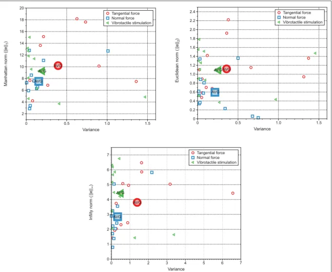
purple circles indicate the median for all tests. . . 38 Figure 2.10 Manhattan norm analysis for the feedback provided by normal
stress, skin stretch and vibrotactile stimulation . . . 39 Figure 2.11 Subjects’ performances under normal stress, skin stretch and
vibrotactile stimulation . . . 40 Figure 2.12 Preference rating in different feedback conditions from the twelve
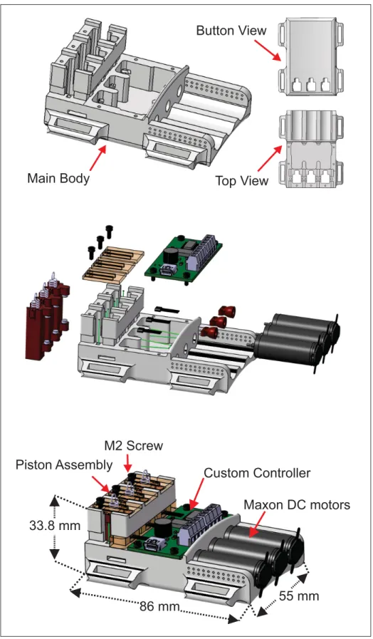
participants . . . 41 Figure 3.1 (a) Microscopic view of a synthetic fiber spectra; (b) Top view of
the haptic device using three Maxon DC motors, hall effect sensors and load springs; (c) Wearable haptic device placed on the glabrous
skin of the human forearm. . . 46 Figure 3.2 (a) Original cable placement before twisting. (b) Maximum
twisting of cable, before double-twisting occurs. (c) Diagram
showing the force from the motor . . . 48 Figure 3.3 (a) Initial arrangement of the mechanism; (b) Secondary
arrangement of the mechanism; (c) Triangle representing the final values of the system’s variables; (d) Triangle representing the final values of the system’s variables with the Pmin; (e) View of the
twisted wire in its final position . . . 49 Figure 3.4 Static analysis for comparisons between the preliminary theoretical
data, the results of the experiments, and the modified theoretical data. During the experiments, four separate tests were conducted using laboratory test weights of 786g, 1184g, 1389g and 1789g. Note that the modified theoretical data have been modified by
taking the torsional stiffness (k= 1.65) into consideration ... 53 Figure 3.5 Comparison between two analyses, each of which represent the
kinematic system as based on the position angle of the motor. The black line is the experimental analysis, and the red line is the theoretical analysis. These analyses were obtained using a bench
Figure 3.8 Schematic view of the haptic interface, including the twisted wire
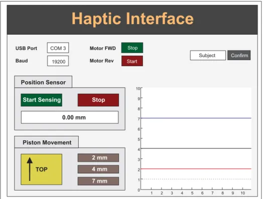
actuator . . . 58 Figure 3.9 Pressure piston that is integrated with the haptic device . . . 60 Figure 3.10 Setup of the force tests. . . 63 Figure 3.11 Results obtained from the force tests . . . 64 Figure 3.12 Haptic interface in GUI-MATLAB for real-time control over the
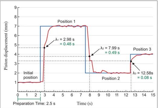
positioning of the piston . . . 65 Figure 3.13 Desired and real-time positioning of the piston, along with the time
constants. . . 66 Figure 3.14 Desired and real time positioning of the piston along with the rise
and response times . . . 67 Figure 4.1 Haptic interface used for applying normal stress and linear
vibration on the human participants. Vib 1 refers to the first vibrator motor, which is at the same location as the piston. Vib 2 refers to the second vibrator motor, which was used to apply
vibrations at a location 6 cm away from the normal stress . . . 71 Figure 4.2 Vibrator motor performance characteristics. The three input
voltages of 1.6 V, 2.6 V and 3.6 V were delivered into the
cylindrical vibrator motor . . . 72 Figure 4.3 Participant applying pressure to the load-cell sensor while
blindfolded and wearing the noise-removal headphones. The red arrow indicates a close-up view of the piston portion of the haptic
device, with the circular unit attached to the top of the piston. . . 73 Figure 4.4 Method of stimulating the normal stress and the vibration onto the
participant’s forearm. Measurements in mm describe the piston’s
displacement from its original position . . . 74 Figure 4.5 Feedback from one participant during the last 20 seconds of each
test . . . 78 Figure 4.6 A subject’s feedbacks from the vibrotactile stimulations in three
Figure 4.8 The fourteen subjects’ feedback under three types of vibrotactile stimuli (V, VP1, VP2). Bars and lines show the absolute mean and the absolute error, and purple circles indicate the median across all
tests . . . 86 Figure 4.9 Static analysis of the Manhattan norm versus variances under
different conditions. The first row belongs to the normal stress stimuli from the 2.8 N to 8.4 N and the second row belongs to the vibrotactile stimuli starting from 1.6 v to 3.6 v. Bigger rectangular, triangle and the circle indicate the average positioning result of all
14 subjects’ feedback . . . 89 Figure 4.10 Preference rating in different feedback condition of the normal
stress stimuli from the 14 participants . . . 90 Figure 4.11 Preference rating in different feedback condition of the vibrotactile
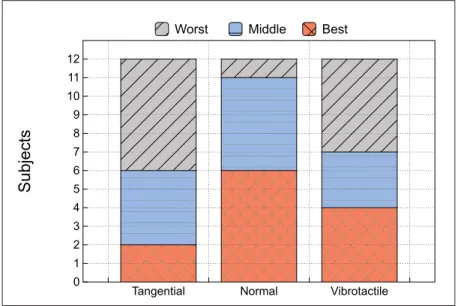
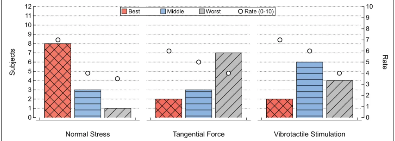
stimuli from the 14 participants . . . 91 Figure 4.12 The overall subjects’ feedback for all types of stimuli. The red
part indicates the number of subjects that performed best with the specific stimulus, the grey part shows the number of subjects who performed worst, and the orange part denotes the number of
subjects who were in-between . . . 92 Figure 5.1 Architecture of the experiment setup . . . 96 Figure 5.2 Robotic components of the haptic system. The sensors provide
normal stress measurements (10−4 N− 20 N per taxel) as well
as dynamic sensing capabilities. (a) Foam used between the two plates of the capacitor, from Rana and Duchaine (2013). (b) Three-finger adaptive robot gripper from Robotiq, Inc., equipped with 10
tactile sensors and mounted on a UR5 Universal Robot . . . 98 Figure 5.3 The haptic interface used to apply normal stress, along with a linear
vibrator motor (Haptuator Mark II) . . . .100 Figure 5.4 Normalized acceleration of the Haptuator Mark II (linear
Figure 5.6 (a) Acrylic textures for the dynamic test. A, B, and C were each engraved to a depth of 0.2 mm and D, E, and F were each engraved to a depth of 0.5 mm. (b) 3D view of the engraved area showing depth of texture B (as an example) with an opto-digital microscope
(OLYMPUS DSX100) . . . .104 Figure 5.7 Comparison of the acrylic textures. The arrows represent the 15
groups . . . .105 Figure 5.8 Static feedback of the subjects based on the applied forces. ±0.5
is considered the safety margin for each level . . . .106 Figure 5.9 Key statistical parameters from the subjects’ feedback under a
static condition. VA represents the variance . . . .107 Figure 5.10 a) Subjects’ correct answers under the dynamic test. More intense
color indicates a better detection ratio. b) The best patterns, based
on the subjects’ feedback . . . .109 Figure 6.1 Architecture of the experiment setup . . . .113 Figure 6.2 Soft dual-layer silicone elastomer used to attach the Haptuator to
the subject’s skin . . . .114 Figure 6.3 Input signals for each texture, of which the amplitude is
proportional to the variation in the movements of the textures that were applied to the sensor’s surface. Notice that all the input
signals are within roughly the same range . . . .117 Figure 6.4 Subjects’ success rates, grouped according to their initial level of
familiarity with vibrotactile feedback. . . .119 Figure 6.5 Rate of successful identification for each individual texture,
according to subjects’ level of familiarity. V indicates subjects that were very familiar with the haptic system, S indicates somewhat familiar ones, and N indicates the subjects that were not at all
familiar with the haptic system. . . .120 Figure 6.6 The average of the success rate for each particular pair of textures,
weeks . . . .124 Figure 6.9 Subject identifying a texture using her index finger . . . .125 Figure 6.10 Subjects’ feedback for each particular texture, when attempting to
recognize textures using the mechanoreceptors in their fingers . . . .126 Figure 7.1 Objects used during the experiment. . . .130 Figure 7.2 UR5 controller used to direct the robotic hand . . . .130 Figure 7.3 Subject controlling the movement of the robotic fingers, while
undergoing familiarization process for the static pressure test . . . .131 Figure 7.4 Soft dual-layer silicone elastomer used to attach the Haptuator to a
person’s skin . . . .132 Figure 7.5 Global view of the haptic device, and close-up view of its
components . . . .133 Figure 7.6 Subject detecting slippage, using vision, dynamic feedback, and
static feedback . . . .134 Figure 7.7 Results of the slippage detection task, based on the average of the
twelve subjects’ results. S indicates the distance of the slippage that occurred during the experiment and SD indicates the standard
deviation . . . .135 Figure 7.8 Subject detecting contact between the robotic fingers and the
object, using either vision or dynamic feedback . . . .137 Figure 7.9 Results of the contact detection tests, based on the average of the
twelve subjects’ results . . . .138 Figure 7.10 The number of errors that occurred during the test of contact
detection using vision. . . .138 Figure 7.11 Subject performing the grasp precision task using vision and
CoRo Control and Robotics Laboratory CÉR Comité d’éthique de la recherche ETS École de Technologie Supérieure
Ee End Effector
FA Fast-Adaptive
Fm Motor force
GPA Dèpartement de gènie de la production automatisèe
GUI Graphic User Interface
MDEIE Ministère du Développement économique, de l’Innovation et de l’Exportation du Québec
MN Manhattan Norm
NIB Neodymium Magnet
NSERC Natural Sciences and Engineering Research Council of Canada PV1 Pressure and vibration applied simultaneously at the same location PV2 Pressure and vibration applied simultaneously at different locations
Pmin Minimum torque
QA Quick-Adaptive
RA Rapid-Adaptive
VP1 Vibration and pressure applied simultaneously at the same location VP2 Vibration and pressure applied simultaneously at different locations
A Area D Diameter f Frequency gr Gram G Gravity k Stiffness factor kg Kilogram L Length
φmin Minimum twisting angles
N Newton
Nm Newton meter
Nm/rad Newton meter per radian
R Radius τs Rotational stiffness rad Radian Tm Rise time sec Second φ Twisting angle
allowing us to feel our way around even when we cannot see. The sense of touch thus allows most people to complete simple tasks without constantly needing to look at what they are doing. Unfortunately, due to the lack of touch sensitivity in current prostheses, upper-limb amputees do not have this ability. To provide tactile receptors to amputees, is, therefore, to provide freedom from the need for constant visual attention.
Despite the progress that medical science has made over recent decades, there has been rela-tively little change in the daily lives of people who suffer from upper-limb amputation. Con-sidering the current number of amputees, this problem affects many people: studies claim that in North America alone, more than 0.3% of people are living with minor or major upper-limb loss or deficiency, and approximately 200,000 amputations occur annually (Biddiss and Chau, 2007; Blank et al., 2010). As a result, a significant portion of the population is dependent on the use of prosthetic limbs.
Although modern prosthetic hands look more like real human hands than their predecessors, most prosthetics still use the conventional hook at the end that does not provide any sensory feedback (Yoshikawa et al., 2013). This forces amputees to rely primarily on their vision to gather information about any types of environmental modalities or the surface properties of objects they encounter. A study of 2,477 upper-limb amputees highlights the qualities that researchers should prioritize Atkins et al. (1996). According to the study’s participants, the ideal prosthetic hand will: 1) allow ordinary tasks to be completed without requiring as much visual attention; 2) allow small and large objects to be grasped more firmly; and 3) be more like a real human hand in overall look and function. Indeed, beyond the simple mechanical structure and limited functionality of current prosthetic hands, the inability to transmit exte-roceptive and proprioceptive information through the nerves makes them extremely difficult to control (Klinge, 1972; Prior et al., 1976; Davis et al., 2000). Overcoming these problems requires a more mechanically-sophisticated prosthesis, such as an under-actuated hand (Baril
et al., 2010). We hope that further developments in this area will provide the enhanced
versa-tility, gripping capability, and touch sensitivity that are so highly in demand.
Aside from mechanical functionality, prosthetic limbs that function at the same level as the human sensory apparatus must be able to sense both static and dynamic events. For unimpaired people, tactile events are detected by an extensive network of tactile receptors that are spread throughout the skin, and that enable the conscious perception of touch (Lederman and Klatzky, 2009; Hager-Ross et al., 1996). Any task that involves the skin coming into contact with an object will activate either the fast-acting (FA) or slow-acting (SA) group of mechanoreceptors, which immediately transmit information through the nerves to the brain so that the person may react properly to the given stimuli (Dargahi and Najarian, 2004; Ferrington et al., 1977). Several researchers have proposed haptic feedback as a way to compensate touch sensitivity to upper-limb amputees (Kim and Colgate, 2012; Bark et al., 2009; Gillespie et al., 2010). A haptic feedback system restores the sense of touch to amputees by completing the communi-cational loop between an external stimulus and an amputee’s brain (Kim et al., 2013). It does this by taking an external stimulus that cannot be perceived by the user, like an object’s texture or motion, and turning it into a different type of stimulus that the user can easily recognize. Sensation of tactile events can thus be restored using a haptic interface that applies normal stress, shear, and vibration to the amputee’s skin (Lee et al., 2004; Caldwell et al., 1999; Oka-mura et al., 1998). However, the haptic system must meet several conditions in order to play the part of the missing tactile receptors: it must be able to sense the surface properties of an object, convert this information into the appropriate type of stimulation, and then apply this stimulation to the user (Kaczmarek et al., 1991; Caldwell et al., 1999), in a way that the user can quickly understand.
Amputees who lack touch sensitivity due to the loss of upper limbs may be able to compensate the sense of touch through the use of a haptic feedback system involving prosthetic fingertips equipped with tactile sensors (Tanaka et al., 2007; Beebe et al., 1998). As can be seen from Figure 0.1, the prosthetic fingers will recognize an object’s properties or grasp quality (i.e.,
how well an object is being grasped by the robotic hand), and transfer this information to the haptic device, which then applies the desired type of stimuli to a healthy part of the user’s skin.
a
d
b
c
Figure 0.1 The loop of human interaction through the sensory robotic hand-gripper and a haptic interface. The tactile sensor (a)
mounted on robotic fingers (b) detects an external event. Tactile information is then transferred to the haptic interface (c) and the device applies the desired stimuli onto the human forearm (d)
Researchers face many challenges in achieving this goal. They must design modern prosthetic limbs that are capable of the same functions as the human hand, and that are optimized to satisfy the amputees who use them.
Objectives and Scope of Study
The main objective of our research is to compensate touch sensitivity to upper-limb amputees through the use of haptic feedback. In the pursuit of this goal, we have several more specific objectives that we must accomplish:
a. To design a wearable haptic device for restoring touch sensitivity under static and dynamic modalities:
• By comparing the effectiveness of normal stress, skin stretch and vibrotactile
stimula-tion to convey informastimula-tion about static events; and
• By prototyping and validating a novel twisting wire actuator-based haptic device, for
providing feedback of tactile pressure information.
b. To examine the effectiveness of haptic feedback during task-oriented experiments:
• By investigating the impact of simultaneously applying two or more types of stimuli
to different areas of the human body; and
• By studying the use of normal stress to convey steady pressure information, and
vi-brotactile stimulation to restore texture recognition capabilities.
The mechanoreceptors in human skin are responsible for detecting a tactile event and transmit-ting it to the nerves. The lack of a sensory system in current prosthetics causes amputees to require continuous visual attention for the accomplishment of any task.
We hope that by means of various tactile sensors mounted on the prosthetic fingers, the needed information will be passed through the haptic interface that is placed on the healthy parts of the amputee’s body. This research is mainly focused on information that has been obtained from tactile sensors, and how this information can be transmitted to amputees via a haptic interface. In this research project, we followed a long goal-oriented approach to provide a functional study that can be used in the next generation of prosthetic applications. We began our research by finding the proper way to stimulate the tactile receptors, according to the conditions of different events (i.e., static or dynamic). We then designed and prototyped a haptic device, and investigated the impact that different types of modalities have on each other. Finally, we carried out several task-oriented experiments in order to prove the functionality of our mechanism.
Impact on Industry and Society
Considering the current state of prosthetics that we have described above, this project has the potential to have a significant social impact by restoring the partial sense of touch to amputees. It may also prove fruitful to investigate the use of haptic devices for industrial robotic applica-tions. For instance, it could be possible for robots to be used in dangerous environments, while haptic feedback allows a human to control the robot from a safe distance away. For this rea-son, our research has been funded by the Natural Sciences and Engineering Research Council of Canada (NSERC) and the Ministère du Développement économique, de l’Innovation et de l’Exportation du Québec (MDEIE).
Organization of the Thesis
Chapter 1 - To carry out the research project, we will need to examine the anatomy of the human body, and the design and assembly of different mechanical components. This section provides a comprehensive review of current touch sensitivity systems, the different mechanisms that can be used for prosthetic applications, and recent approaches that have been used in haptic technology.
Chapter 2 - The first phase of the project is to explore the different methods that can be used to convey static event information. In this section, we conduct an experiment to compare the exteroceptive feedback of normal stress, tangential force, and vibrotactile stimulation, in which each device provides feedback while pressure is applied to the finger pads of human subjects. The subjects then attempt to press on a force sensor with the same amount of pressure that the devices had conveyed to them through the haptic feedback. Results show that normal stress (normal pressure) is a functional way to convey static pressure information.
Chapter 3 - We present our design of a wearable haptic device, that can apply pressure based on the information that it receives from a tactile sensor, and that is based on a twisted wire actuator. The third chapter of this thesis will describe the whole procedure: the background of
the twisted wire mechanism, kinematic and static analysis, the design process, and the tests for validation under different conditions.
Chapter 4 - Here, we investigate how the simultaneous application of two different types of haptic feedback impacts human sensory perception. Now that we have designed a haptic device for the purpose of applying pressure, by means of a vibrator motor implemented with the mechanism, we can apply both vibrotactile stimulation and normal stress at the same time. Our experiments test whether subjects experience more or less accurate sensory perception when vibration is applied in different combinations: at the same time as the normal stress, at a different time, at the same location, and at a different location (6 cm away).
Chapter 5 - In this section we develop a robotic system that is used to study the restoration of touch sensitivity. The robotic system is composed of a combination of tactile sensors, robotic fingers, and a haptic interface. We conduct two separate tests on eight human subjects in order to assess the effectiveness of the static and dynamic modalities in different detectable ranges of skin sensitivity.
Chapter 6 - We present a vibrotactile haptic feedback system for use under dynamic conditions, verify its functionality, and show how results may be affected by the amount of training that subjects receive. We hope that by using vibrotactile feedback to distinguish between different textures, upper-limb amputees may be able to partially compensate the sense of touch.
Chapter 7 - We test a robotic sensory system (that includes the use of haptic feedback) by having subjects attempt to use it to carry out simple tasks that humans may encounter in their everyday lives. These tasks require grasping, pushing, and pressure-application skills, in order to determine the functionality of the proposed mechanism under various conditions.
Chapter 8 - In the last section of this thesis, we conclude our research and discuss the work that remains to be done in future studies.
1.1 Introduction
To carry out the research project, we will need to examine the anatomy of the human body, and the design and assembly of different mechanical components. The present section provides a comprehensive review of current touch sensitivity systems, the different mechanisms that can be used for prosthetic applications, and recent approaches that have been used in haptic technology.
We begin the section by briefly defining some critical terms in the field of touch sensitivity. Our discussion will include an overview of human tactile receptors, their capabilities, and the correct method of stimulating them. We will then consider the different mechanisms that have been used in haptic technology, to provide the context for our innovations in this area. Finally, we will discuss the scientific originality of our research.
1.2 General Definitions
1.2.1 Somatosensory Systems
Human skin involves a vast network of nerve endings and tactile receptors called the so-matosensory system. Johansson and Vallbo (1979) estimate that more than 17,000 tactile receptors exist in the glabrous skin area of the hand alone. The somatosensory system al-lows us to recognize the tactile properties of an object, and react to any external events that occur during physical contact with the object. Patrick Dougherty (2013) has shown that the system also provides proprioceptive information, allowing us to know how our body parts are spatially positioned. This system also informs us of pain, itching, environmental temperature, and in general anything related to our surroundings.
As shown in Table 1.1, the sensation of pain, temperature, touch, and proprioception are the fundamental modalities that are processed by the somatosensory system. Each of these modal-ities, depending on its type and intensity, can also be divided into several sub- and modalities. For example, discriminative touch can divided into four different sensation sub-modalities, namely vibration, flutter, pressure, and simple touch.
The next two sections of the table involve the different anatomical pathways along which the sensory information travels. As one can see by looking at the list of somatosensory pathways, this information is carried by certain neurons, based on the type of tactile information that the neurons are conveying. For instance, based on the literature provided by Patrick Dougherty (2013), the spinothalamic pathways carry information regarding the pain and temperature of the body, whereas the spinal trigeminal pathway carries the same information from the face. For discriminative touch and proprioception, this process is limited to the medial lemniscal (body) and main sensory trigeminal (face) pathways.
Table 1.1 The sensory modalities represented by the somatosensory system (Patrick Dougherty, 2013)
Modality Sub Modality Sub-Sub Modality Somatosensory Pathway (Body)
Somatosensory Pathway (Face)
Pain sharp cutting pain - Neospinothalamic
Spinal Trigeminal deep aching pain - Archispinothalamic
Temperature warm / hot - Paleospinothalamic cool / cold - Neospinothalamic
Touch
itch, tickle & crude touch - Paleospinothalamic discriminative touch
touch
Medial Lemniscal Main Sensory Trigeminal pressure
vibration
Proprioception
Position: Static Forces
muscle length muscle tension joint pressure
Movement: Dynamic Forces
muscle length muscle tension joint pressure
1.2.2 Somatic Stimuli
Mechanical forces such as vibration, pressure, temperature changes, and even chemical reac-tions are the somatosensory stimuli to which the neurons are most sensitive. Among them, discriminative touch, and the proprioceptive systems (as shown in Table 1.1) are the ones that are most sensitive to a variety of mechanical forces. These forces include normal and tangential forces which result in skin displacement and shear (skin stretch), and the linear and rotational vibrations that characterize dynamic sensitivity capabilities.
1.2.2.1 Tactile Stimuli
Tactile stimuli are the external forces that are applied to the skin during physical contact. These forces enable us to perceive discriminative touch. Each of the sub-sub sensory modalities provides a certain type of touch sensitivity depending on how the object is being manipu-lated (Davis et al., 2000). For instance, a minimal force resulting from the brief touch of an object results in very little distortion of the skin (Patrick Dougherty, 2013). This nominal force can become a greater force and can cause so much skin displacement in the given direction that it is finally categorized as the pressure in discriminative touch. Also, the movement of skin across a rough surface can provide motion sensitivity to the skin.
1.2.3 Exteroception and Proprioception
Exteroception and proprioception, which are also known as supplementary sensory feedback, are the fundamental parameters that enable us to interact with our surroundings (Davis et al., 2000; Prior et al., 1976). Exteroception is the feedback of cutaneous receptors reacting to various stimuli originating from outside the body (Childress, 1980). These outer stimuli can involve touch, pain, taste, or whatever is imposed by the environment. Proprioception is defined as the intuitive sense, with no visual attention required, of the relative positioning of one’s body parts in space (Blank et al., 2010).
1.2.4 Sensory Receptors (Mechanoreceptors)
In the somatosensory system, mechanoreceptors are among the skin receptors that enable hu-mans to recognize a variety of environmental modalities. These modalities include pressure, skin stretch, skin motion, the temperature of a contact surface, and high frequency vibrations (such as the vibrations that occur when an object is slipping out of one’s grasp, or when one’s hand is sliding across a surface). These modalities are the main parameters of skin sensa-tions (Gonzalez-Crussi, 1989; Caldwell et al., 1997; Provancher et al., 2005). As shown in Figure 1.1, in the glabrous skin area there are four types of tactile units, which are classi-fied according to the presence of two features: i) the structure of their receptive fields and ii) their rate of adaptation to sustained indentation (Vallbo et al., 1984). These features enable researchers to place each type of mechanoreceptors into one of two categories, according to the speed of their adaptability: Fast-Adaptive (FA) and Slow-Adaptive (SA).
Epidermis Dermis Meissner corpuscle Ruffini endings Pacinian corpuscle Hair receptor Merkel disk Hairy skin Free nerve ending Septa Papillary Ridges Glabrous skin
Figure 1.1 The locations of cutaneous receptors in the skin (Boundless, 2014)
Table 1.2 Summary of the location and function of skin mechanoreceptors (Dargahi and Najarian, 2004; Patrick Dougherty, 2013)
Receptor Location Activation Stimuli
Hair Follicle Ending Hairy skin areas Hair displacement
Ruffini Endings Dermis of hairy and glabrous skin Pressure and skin stretch
Pacinian Corpuscle Deep layers of dermis Motion and vibration
Meissner’s Corpuscle Dermis of glabrous skin Flutter and vibration
Free Nerve Endings Throughout the skin Tissue damage and changes in temperature
Merkel Disk Epidermis of glabrous skin Pressure and texture
Table 1.3 Characteristics of skin mechanoreceptors (Caldwell et al., 1997)
Receptor Class Receptive Field (mm2) Frequency Range (Hz) Receptors (cm2)
Pacinian Corpuscle FC 10–1000 0–800 21
Meissner’s Corpuscle FA 1–100 10–200 140
Ruffini Endings SA II 10–500 7 49
Merkel Disk SA I 2–100 0.4–100 70
FA receptors are also known as Rapid Adapting (RA) or Quick Adapting (QA) mechanorecep-tors. Researchers have estimated that more than 56% of the total number of tactile units consist of FA units. There are two sub-categories of FA mechanoreceptors, known as FA I and FA II (Figure 1.2). The first type, FA I, consists of Meissner corpuscles, and makes up 43% of the total number of tactile units. These occupy a small receptive field. The second type, FA II,
Capsule
Laminar cell
Terminal Axon
Single nerve fiber
Myelin sheath Capsule
Pacinian Corpuscle Meissner Corpuscles
Figure 1.2 Fast adapting (FA) tactile receptors (Gallery, 2014)
consists of Pacinian corpuscles, and occupies a large receptive field. FA II receptors make up 13% of the total number of tactile units.
According to a terminology introduced by Iggo and Muir (1969), the Meissner corpuscles, located in the deep layers of the dermis, generally respond to pressure on the skin and to texture. The Pacinian corpuscles, meanwhile, are located in the epidermis of the glabrous skin area and respond directly to motion and vibration (Dargahi and Najarian, 2004; Provancher
et al., 2005).
SA tactile receptors are also sub-divided into SA I and SA II types. By comparison with the FA units, the SA tactile units constitute a smaller number of tactile units of the glabrous skin of the hand. Out of the 17,000 total tactile units, SA receptors make up approximately 44% (25% SA I and 19% SA II). In this group, Merkel nerve endings (Merkel Disk) in SA I and Ruffini Endings in SA II are considered the main tactile receptors (Figure 1.3). In accordance with Dar-gahi and Najarian (2004), the majority of Merkel Disks receptors are scattered throughout the epidermis of the glabrous skin area with the aim of responding to pressure applied to the skin and to texture. By contrast, the Ruffini Endings are typically distributed in the dermis of hairy and glabrous skin areas and respond to pressure and skin stretch.
Bundles of callagenic fibers
Terminals branches of afferent fiber
Capsule Myelin sheath
Terminal disk of afferent fiber
Merkel Disk Ruffini Endings
Figure 1.3 The slow-adaptive (SA) tactile receptors (Gallery, 2014)
1.2.5 Sensory Transduction
The membranes of both FA and SA mechanoreceptors contain bunches of ion channels that respond to various mechanical distortions by changing the amount of sodium and potassium. In this regard, the magnitude and duration of the applied forces have a direct relationship with the impulses. Whenever the magnitude of the applied forces is greater, there will be greater depolarization of the ion channels. By contrast, forces that are applied for a greater length of time will take longer to depolarize.
As shown in Figure 1.4, mechanoreceptors encode the tactile information as a series of pulses, similar to those used in digital serial communications. These serial communications may vary depending on the magnitude of the force that is applied to certain types of tactile receptors. However, the behavioral responses of these receptors, whether regular or irregular, follow a unique pathway for each type. A summary of the mechanoreceptors’ locations, functions, characteristics, and physical parameters is presented in Table 1.2 and Table 1.3.
SA I SA II FA I FA II
Irregular
Merkel disk: 25%
Regular
Ruffini endings: 19% Meissner corpuscle: 43% Pacinian corpuscle: 13%
Figure 1.4 Responses of the four types of mechanoreceptors to normal indentation of the skin. The percentages listed indicate the relative number of each type of receptor that
is found in the skin of a human fingertip (Goodwin et al., 1997)
1.2.6 Touch Sensitivity Thresholds of Various Areas of the Human Body
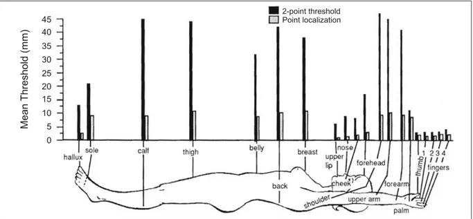
Lederman and Klatzky (2009) have presented an overview of human body perception (Fi-gure 1.5). They provide information about “what” and “where” a system deals with perceptual functions. Figure 1.5 depicts the sensitivity thresholds of various parts of the human body, as measured by Weinstein (1968). The measurements are presented according to the results of two different methods: the point-localization method and the two-point threshold method.
45 40 35 30 25 20 15 10 5 0 Mean Threshold (mm) 2-point threshold Point localization
Figure 1.5 Two-point threshold and point localization measurements are shown for various areas
(Lederman and Klatzky, 2009)
1.2.7 Mechanoreceptor Stimulation Methods
There are a number of ways to stimulate tactile receptors. With regards to the objective of the present research, here we describe the most fundamental types of stimuli: normal stress (normal force), vibrotactile stimulation, and skin stretch (tangential force, shear force).
1.2.7.1 Normal stress
As shown in Figure 1.6, any compressing strain on the skin activates Merkel Disk and Ruffini Endings receptors. These are categorized as SA mechanoreceptors (Dargahi and Najarian, 2004), and are located in the epidermis of the glabrous skin area. They typically respond to steady pressure on the skin and to surface textures, and they provide the sense of contact with an external stimulus when it is applied slowly.
Within a haptic feedback system, applying pressure to the skin is considered the best way of informing us of any static modalities occurring in our surroundings. Normal stress can be used
Normal Force
Figure 1.6 Normal force applied to the fingertip
at different magnitude levels, based on the amount of force that the object is applying to the skin (and vice-versa).
1.2.7.2 Vibrotactile Stimulation
The FA mechanoreceptors (Meissner and Pacinian Corpuscles) are not activated by pressure, but by vibration. This stimulus can be used for the feedback of dynamic modalities in a variety of receptive fields (Silverthorn, 2003). The FA receptors are very sensitive to even the slightest of variations, and react immediately to the given stimulation (Russell, 1990). Previous studies of vibrotactile stimuli have identified a functional range of 100− 300 Hz to ensure the proper stimulation of FA mechanoreceptors (Biggs and Srinivasan, 2002; Caldwell et al., 1999). Vibration is particularly useful in prosthetic applications due to its fast and convenient ability to restore a sense of motion (Damian et al., 2011; Fortin et al., 2014). It can be applied directly to the skin, and patients can quickly recognize its effect. Furthermore, when multiple vibrator motors are placed on the skin, vibrotactile stimulation can be used to provide a sense of mo-tion and direcmo-tion (Tan et al., 2003). Among the various types of vibramo-tion motors available on the market, pancake and cylindrical motors are most frequently used in haptic interfaces (Biggs and Srinivasan, 2002; Yao and Hayward, 2010). Schätzle et al. (2006) have stated that pancake motors cause the skin to feel something like shear forces whereas cylindrical motors
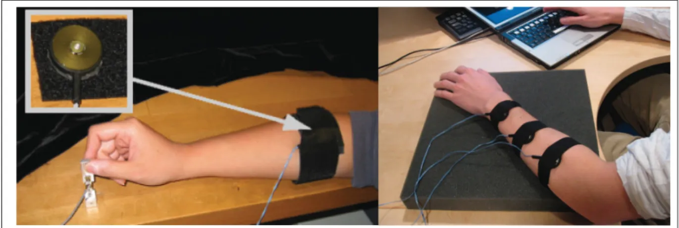
Figure 1.7 Vibrator motor attached to a person’s forearm in order to provide haptic feedback
(Bark et al., 2008)
cause normal forces. Both types of motors are compact in size and feature a wide range of vi-brational amplitude and intensity; and both motors can stimulate vibration by using unbalanced inertia at various frequencies and amplitudes, based on the input voltage level.
1.2.7.3 Tangential Force and Skin Stretch
Unlike vibration, tangential forces result in skin stretch, which can activate both SA and FA cutaneous mechanoceptors. This stimulus is considered as a well-defined solution for use in wireless devices due to its low level of required power supply. Tangential forces are widely considered to be ideal for use in wireless devices due to the fact that they require a relatively small power supply. Previous approaches have thoroughly described the quick and accurate re-sponses of mechanoreceptors to skin strain change (Edin, 2004; Paré et al., 2002). Researchers have also developed innovations in the mechanisms behind the skin stretch (LaMotte et al., 1998; Edin, 2001; Bark et al., 2009). However, the impacts of skin stretch on the non-glabrous skin area in comparison with the hairy area have been largely unexplored.
Skin deformation
Tangential skin stretch Interaction
force
Figure 1.8 Tangential skin stretch evoked while holding a pen (Kirk et al., 2015)
1.2.8 Haptics
According to Robles-De-La-Torre (2006), “haptics refers to the ability to experience the envi-ronment through active exploration, typically with our hands, as when palpating an object to gauge its shape and material properties.”
In general, the word haptics refers to all touch-related exteroceptive and proprioceptive sensory capabilities. In this regard, haptic devices play a critical role in transmitting the sense of contact between the skin and objects. These devices are classified into either grounded or portable classes, as described below.
In the grounded class, the device is in a fixed location, limiting the freedom of motion of the user. This group of devices is capable of performing fixed-object simulation (Figure 1.9). Typi-cally, tapping on both surfaces in a virtual environment and a soft foam, provides same feelings with this kind of haptic devices. Academic environments and industrial research laboratories are the primary users of this type of haptic device. The main advantages of these devices are the possibilities they offer for use within a virtual environment, and for simulating virtual touch sensitivities.
Figure 1.9 Left: High-definition haptic device. Right: PHANTOM Omni (Sensable, 2012; Quanser, 2013)
Portable haptic devices are capable of interacting with their surroundings without major restric-tions (Figure 1.10). These types of haptic devices can be used in modern prosthetic limbs, and in industrial robotic applications, due to the freedom of the user’s movement. For this reason, portable haptic devices will be the main focus of the present work.
Figure 1.10 Haptic devices for the restoration of touch sensitivity (Dexta, 2014)
1.3 Related Works
Researchers have integrated haptic feedback with robotics in the hope of adding touch sen-sitivity to prosthetic limbs. In this section, we examine the different approaches that employ haptic feedback, and discuss the human touch sensitivity in different body organs. Finally, we describe the novel haptic interfaces that can be used in prosthetic applications.
1.3.1 Comparing the Advantages of the Different Types of Haptic Feedback
This subsection will begin with a description of pressure, and explain the types of static stimuli that can be used to convey pressure. The feedback can be applied vertically or tangentially, according to the desired effect. After going over these functionalities, we will proceed with a comparison of several other types of haptic feedback.
Applying pressure to one or two sides of the skin, or grasping a part of the body (e.g., an arm), can provide some information about vertical skin displacement (Figure 1.6). In this re-gard, Biggs and Srinivasan (2002) have investigated the relative effectiveness of tangential and normal skin displacement for producing tactile sensations. The authors state that “At both fore-arm and finger pad, subjects chose tangential displacements only 0.3 to 0.6 times as large as the reference normal displacement, indicating a significantly higher sensitivity to tangential displacement.” The second key finding of this experiment is the greater sensitivity of the fore-arm to tangential force rather than normal force. By contrast, “the sensitivity of the finger pad to tangential force is lower than the normal force due to the approximately five-fold greater stiffness of the finger pad to tangential traction.”
Narrowing over tangential forces, Paré et al. (2002) have provided the estimated magnitude of the tangential force that is applied to the distal pad of the index finger. They tried to de-termine the human tactile sensitivity in different levels of the tangential forces ranging from
0.15 to 0.70N. As shown in Figure 1.12, they realized that the majority of the human
1.5 mm REF S2 AVG DISTAL PROXIMAL Side Top Top Side Side Side Top Top B P M Message on screen REF Blank ADJ Probe Displacement (mm) 2 0 0 t (sec) 8 Reference
Stimulus Adjustable Stimulus Tangent plane Sagittal plane Or Displacement (mm) 2 1.5 1 0.5 0 Force (mN) 500 300 0 100 200 400
Figure 1.11 Points of subjective equality are shown for skin displacements in various directions on the finger pad (left column)
and hairy skin of the forearm (right column). Plots at bottom, averaged over five subjects (AVG) showed no statistically significant difference in subjects’ responses to displacements in
different tangential directions (Biggs and Srinivasan, 2002)
and the tangential forces. This led us to consider the potential of the skin stretch for further investigation.
Normal force
Spatula Moving rod
Tangential force Tangential force Normal force Tangential force A B Stimulus level
Figure 1.12 Histogram of mean applied force (five trials) for the seven force magnitudes and three rates of force application for both tangential (A) and normal (B)
forces of one subject, along with the minimum and maximum values (error bars) (Paré et al., 2002)
Relative Position Error
0.7 0.6 0.5 0.4 0.3 0.2 0.1 Feedback Types A verage Ending V elocities (grid units/sec) 2 1.5 1 0 Feedback Types
Figure 1.13 No feedback (NF1), vibration (V), skin stretch (SS), and the final no feedback case (NF2)
Biggs and Srinivasan (2002) believed that the tactile receptors on hairy skin are more sensi-tive to tangential force, whereas the receptors on glabrous skin and the finger pads are more sensitive to normal force.
Bark et al. (2008) compared the proprioceptive information of the skin stretch and the vibrotac-tile feedback (Figure 1.13). Their results showed that skin stretch (shear force) provides more reliable feedback, especially when the haptic device operates at low velocity and under low inertia. The authors suggest that the use of compact devices for applying shear force could be a good choice when worn on the human body. These devices can be used in different experiments that involve virtual environments, such as motion training during rehabilitation processes, and athletes’ training.
Figure 1.14 A) Placement of one of the mechanotactile stimulators on amputee’s residual limb. B) Representative placement of a vibrotactile stimulator. C) Setup of experiment. D) Representative placement of vibrotactile stimulators on forearm of
healthy subject (Antfolk et al., 2013)
Another interesting application is mapping (phantom hand mapping). Antfolk et al. (2013) set up an experiment on eight transradial amputees to assess their ability to distinguish between multi-site tactile stimuli in sensory discrimination tasks (Figure 1.14). They had two separate groups of participants (A and B) that were divided according to the integrity of their
phan-tom map. The A group contained participants with an intact phanphan-tom map on their residual limbs, whereas the group B contained participants with an incomplete or non-existent map. Results indicated that pressure provides more reliable feedback than vibration in multi-site sensory feedback tests. The researchers also showed that the participants of group A had better discrimination performances than those of group B.
1.3.2 Haptic Devices for Prosthetic Applications
A vast number of haptic devices have been developed for prosthetic applications with the goal of providing amputees with touch sensitivity. In this section, we explain the different types of haptic devices that are more specifically related to our applications.
a
b
c
Figure 1.15 Prosthetic limbs used haptic devices (Chatterjee et al., 2008; Kim et al., 2010; Kargov et al., 2007)
Srinivasan and Basdogan (1997) states that the human hand consists of 19 bones, which are connected by joints and covered by soft tissues and skin. In order to develop a haptic interface designed for optimal interaction with the amputee, it is necessary to fully realize the role of
the sensory, mechanical, and cognitive subsystems of the haptic device. To this end, a haptic feedback stimulator has been designed by Chatterjee et al. (2008) to assess the control of the grasp force at three different target force levels. A series of tests, done on eight subjects, proved that the control of the grasping force in prosthetic users can be improved by using a haptic feedback system (Figure 1.15 a). Clearly, it will be important to integrate haptic feedback systems with prosthetics in order to improve the user’s experience.
Figure 1.16 The ergonomic cuff worn on the residual limb of a lowerlimb-balloon based haptic feedback actuator. Left: no
inflation. Right: Full hemispherical inflation (Fan et al., 2009)
While our study is focused on prosthetic applications, it is interesting to note how haptics are used in the surgical field as well. Kim et al. (2010) presents a design of a miniature haptic device for upper-limb prostheses. Interestingly, this device is capable of conveying numerous aspects of touch to the skin of an upper-limb amputee, including normal and shear force (static), vibration (dynamic), and temperature (thermal). It is especially effective for females who have had tubal reserval surgery (TR) (Figure 1.15 b).
A
B
C
Figure 1.17 A) The master device for real-time control of the dragger. B) Vibrotactile rehabilitation system. C) Skin stretch
haptic interface attached to subject’s arm
(Stanley and Kuchenbecker, 2011; Kapur et al., 2009; Wheeler
et al., 2010)
Kargov et al. (2007) describe the development of a multifunctional device capable of restor-ing sensory and motor ability to the amputees. The paper discusses the high-power actuatrestor-ing method that the researchers used to maximize the potential benefit of using upper-limb pros-thetics. It also describes how mechanical vibration can be used to obtain the optimal sensory feedback (Figure 1.15 c).
After presenting technology that uses haptic devices to compensate touch sensitivity, it is time to focus more precisely on haptic interfaces that have been mainly developed as independent devices to restitute one or multiple modalities in the human subject. For instance, Fan et al. (2009) have developed a haptic feedback rehabilitation system that can be used for lower-limb amputees. Their haptic device is actually a balloon-based actuator that can restore the tactile feedback of static events (Figure 1.16).
As can be seen from Figure 1.17, there are a number of devices that can compensate touch sensitivity to upper-limb amputees through the use of different types of haptic feedback (nor-mal forces, vibrotactile, and skin stretch). Stanley and Kuchenbecker (2011) have designed a
Figure 1.18 Top-Left: Multimodal BioTac tactile sensor. Top-Right: Prosthetic hand equipped with multimodal tactile sensors Bottom-Left: Various tactors. Bottom-Right: Tactors
worn by subject (Jimenez and Fishel, 2014)
wearable body-grounded tactile actuator for feedback of human physical contact (Figure 1.17 A). Kapur et al. (2009) have created a vibrotactile feedback system made by different tac-tors for intuitive upper-limb rehabilitation (Figure 1.17 B). Finally, Wheeler et al. (2010) have investigated the rotational skin stretch with a myoelectric haptic application (Figure 1.17 C).
The work that is most similar to what we are doing, in designing a haptic device, is by Jimenez and Fishel (2014) and Matulevich et al. (2013). As can be seen in Figure 1.18, they have designed a
wear-able haptic device to evaluate the force, vibration, and thermal tactile feedback in prosthetic limbs. As they describe, the proposed system can transmit tactile information to the amputee in order to identify the weight, temperature, and thermal properties of the objects or surfaces in contact.
1.4 Scientific Originality of the Research
For years it was believed that prosthetic devices could never convey an artificial sense of touch to users, because of the complex structure and external power supply and control systems that they would require. However, over the past two decades continuous progress in haptic technology has restored hope in the prospect of providing amputees with the sense of touch. While much work has been done towards this goal, our review of the literature showed that the majority of research in haptics and prosthetics has focused on a single area. In prosthetics research, the main focus was on conveying proprioceptive, rather than exteroceptive feedback. In haptics research, many haptic devices have been designed to convey just one type of feed-back, generally either pressure, skin stretch, or vibration, so they are suitable for use under either static or dynamic conditions, but not both. Few researchers, meanwhile, have attempted to convey multi-modal exteroceptive feedback by means of portable haptic devices, for use in prosthetic and industrial applications. As concluded by Chatterjee et al. (2008), neither the current commercially-available prosthetic devices, nor the latest versions that have come out of research laboratories, are very portable and easy-to-use.
At present there is a need for more multi-responsive actuated devices. We aim to design a portable haptic device that will apply both pressure and vibrotactile feedback to the user, so that the device can be used for conveying information under both static and dynamic condi-tions. The simultaneous application of multiple types of feedback might help amputees to minimize, and possible even eliminate, the visual attention they must pay during everyday life. Furthermore, our research will attempt to answer several questions. These include: what is the optimal type of exteroceptive feedback for conveying information through the human sensory system? Which area of the body is most effective at recognizing such haptic feedback?
From a design perspective, we intend our device to be portable, light-weight, and durable, as well as effective enough to have a significant impact on the market for prosthetic devices. Finally, we hope our research will inspire further investigation in this field.
2.1 Introduction
In this chapter, we seek to determine the most effective type of haptic feedback, whether nor-mal stress, tangential force, or vibrotactile stimulation, for conveying a level of force that is applied to the subjects’ finger pads. Our main goal is to use haptic feedback to alert amputees about how their prosthetic limb is interacting with the environment. The results could pave the way for further research in developing a prosthetic hand system that uses haptic feedback to compensate for the dearth of touch sensitivity.
To this end, we begin by describing the technological components of our experiment, specif-ically the actuator and vibrator motor that we used. We then discuss the procedure of the experiment, including the participants and the exact method that was used to produce the static and dynamic stimuli. Next we present our results and explore the functionality of each type under static conditions. We conclude with a discussion of the factors influencing our results, and explore how future work might improve upon our current study.
2.2 Materials and Methods
As can be seen from Figure 2.1, the experiment was performed using three types of feedback: normal force, tangential force, and vibrotactile stimulation. The protocol of our experiment was approved by the Ethics Committee of Research (Comité d’éthique de la recherche, or CÉR) at École de Technologie Supérieure (ÉTS), Montréal, Canada.